
Manuels Connexes pour Burkert TOP Control on/off 8631


Sommaire des Matières pour Burkert TOP Control on/off 8631
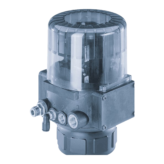
- Page 1 Type 8631 TOP Control on/off Operating Instructions Bedienungsanleitung Manuel d‘utilisation...
- Page 2 We reserve the right to make technical changes without notice. Technische Änderungen vorbehalten. Sous réserve de modifications techniques. © 2000 - 2011 Bürkert Werke GmbH Operating Instructions 1106/12_EU-ML_00801872 / Original DE...
-
Page 3: Table Des Matières
ONTENTS Contents Operating Instructions TOP Control on/off Type 8631 GENERAL NOTES Symbols ..................................................Intended use ................................................Safety notes ................................................Notes for units with EEx-i approval ..................................Notes for use in the Ex-area ......................................Scope of delivery ............................................Warranty conditions ............................................. Transport, storage ............................................ - Page 4 ONTENTS COMMISSIONING Fluidic installation ............................................Installation of the valve ........................................Turning the TOP Control on/off ................................... Fluidic connection of the TOP Control on/off ..........................Opening the housing ........................................Electrical installation ..........................................Connection terminals for cable bushings ..............................24 V - version with inductive proximity switches (make contacts) ................
- Page 5 ONTENTS Configuring of the process data ....................................LED status display ............................................Statuses of the MNS LED ....................................... Example of configuration ........................................Installation of the EDS file ........................................ Setting upt the process map ......................................SAFETY SETTINGS AND MAINTENANCE Safety positions following failure of electrical and pneumatic auxiliary power .........
- Page 6 Contact addresses can be found on the internet at: Die Kontaktadressen finden Sie im Internet unter: Die Kontaktadressen finden Sie im Internet unter: Les adresses se trouvent sur internet sous : Les adresses se trouvent sur internet sous : www.burkert.com www.burkert.com Bürkert Bürkert Company...
-
Page 7: General Notes Symbols
ENERAL OTES GENERAL NOTES Symbols ....................................................Intended use ................................................... Safety notes ..................................................Notes for units with EEx-i approval ....................................Notes for use in the Ex-area ........................................Scope of delivery ..............................................Warranty conditions ............................................. Transport, storage ..............................................Disposal ....................................................8631 - 5... -
Page 8: Intended Use
ENERAL OTES Symbols The following symbols are used in these operating instructions: Marks a work step that you must carry out. ATTENTION! Marks notes on whose non-observance your health or the functioning of the device will be endangered. NOTE Marks important additional information, tips and recommendations. Intended use In order for the device to function perfectly and have a long service life, you must observe the information given in these operating instructions and comply with the operating conditions and the permissible data... -
Page 9: Notes For Units With Eex-I Approval
ENERAL OTES Notes for units with EEx-i approval • Take suitable measures to avoid an electrostatic discharge from the plastic parts of the housing (see EN 100 015 - 1). • No component should be connected to the inputs and outputs of the circuit board whose electrical data is outside the limits determined for intrinsically safe operation quoted in the data sheet of the positioner. -
Page 10: Transport, Storage
ENERAL OTES Transport, storage ATTENTION! Transport and store the appliance in its original packing only. Disposal ATTENTION! When disponsing of the appliance, observe the national standards for refuse disposal. 8 - 8631... -
Page 11: Technical Data
ECHNICAL TECHNICAL DATA Construction and function ........................................... Features ....................................................Operating conditions ............................................Conformity ..................................................Mechanical data ................................................ Pneumatic data ................................................Electrical data without bus control ....................................Electrical data with bus control (AS interface) ............................. Electrical data with bus control (DeviceNet) .............................. -
Page 12: Construction And Function
ECHNICAL Construction and function The TOP Control on/off serves to drive pneumatically actuated process valves. It may be combined with various vbalve types from the Bürkert process valve range (see data sheets for types 2000, 2001, 2002, 2012, 2030, 2031, 2031K, 2652, 2655 and 2658). TOP Control and process valve are connected by an adapter. -
Page 13: Features
ECHNICAL Features Versions for single and double-acting solenoid valves Control valves Solenoid valve working on the rocker principle 1 x 3/2-way control valve with single-acting valve actuators 2 x 3/2-way control valve with double-acting valve actuators TOP Control on/off with EEx-i approval: Pilot valve - solenoid valve with EEx-i approval (PTB 01 ATEX 2173) Electrical interfaces Cable bushings with screw terminals... -
Page 14: Operating Conditions
ECHNICAL Operating conditions ATTENTION! The TOP Control on/off is not suitable for outdoor use! TOP Control on/off with EEx-i approval: Note the Manufacturer's Declaration for proximity switches. Operating temperature -10 ... + 50 °C Protection type IP 65 to EN 60529 TOP Control on/off with EEx-i approval: Type of "e"... -
Page 15: Electrical Data Without Bus Control
ECHNICAL Electrical data without bus control Connections 2 x M16 cable bushings with screw terminals for cable cross-sections 0,14 ... 1,5 mm² Voltage supply 24 V DC ± 10 % residual ripple 10% ATTENTION : Do not use industrial DC! 110 V AC / 230 V AC Power consumption <... -
Page 16: Electrical Data With Eex-I Approval
ECHNICAL Electrical data with EEx-i approval Connections 2 x M16 cable connector with screw terminals for cable cross-sections 0,14 ... 1,5 mm² Sensor power supply see Manufacturer's Declaration form Fa. Pepperl & Fuchs (siehe Anhang) Valve power supply see Qualification Test Certificate PTB 01 ATEX 2173 (siehe Anhang) Safety requirements he maximum permissible voltages and the associated maximum permissible short-circuit currents for the... - Page 17 OMMISSIONING COMMISSIONING Fluidic installation ..............................................Installation of the valve ..........................................Turning the TOP Control on/off ......................................Fluidic connection of the TOP Control on/off ..............................Opening the housing ............................................Electrical installation ............................................Connection terminals for cable bushings ................................24 V version with inductive proximity switches (make contacts) ..................
-
Page 18: Commissioning Fluidic Installation
OMMISSIONING Fluidic installation See the relevant data sheet for dimensions of TOP Control on/off and the variants of the complete device, consisting of TOP Control on/off, pneumatic actuator and valve. Installation of the valve For dimensions and threads, see data sheet for the process valve. Turning the TOP Control on/off If, after installation of the continuous valve, the LEDs of the TOP Control on/off are poorly visible or it is difficult to attach the cable or hoses, the TOP Control on/off may be rotated relative to the pneumatic... -
Page 19: Electrical Installation
OMMISSIONING Electrical installation For making electrical contact to the TOP Control on/off, various connection concepts are available. Terminal allocation for cable bushings or plug connectors for bus control is explained in the following. Connection terminals for cable bushings Open the housing. Connect the wires th the terminals (see connection allocation). -
Page 20: Version With Inductive Proximity Switches (Make Contacts)
OMMISSIONING 24 V - version with inductive proximity switches (make contacts) Terminal Allocation External connection Valve actuation GND 0/24 V DC ± 10 % residual ripple 10 % Valve actuation 0 V / 24 V Initiator supply GND Common reference for initiators GND +24 V DC not connected Output 1 (0V/24V) -
Page 21: Electrical Installation Of The Top Control On/Off With Eex-I Approval
OMMISSIONING 230 V - version with mechanical limit switches Terminal Allocation External connection Valve actuation N Valve actuation L1 Limit switch supply Output common pole Output limit switch 2 (NC) NC1 (max. 5 A) NO1 (max. 5 A) Output limit switch 2 (NO) NC2 (max. - Page 22 OMMISSIONING Terminal allocation - TOP Control on/off with EEx-i approval Terminal Connection External circuitry Valve control + Signal from barriers see PTB 01 ATEX 2173 Valve control - Proximity sensor 1+ (according to NAMUR Proximity sensor 1 - recommendation) Please also note the Manufacturer's Declaration from Proximity sensor 2+ Pepperl &...
-
Page 23: As Interface
NTERFACE AS INTERFACE Programming data ..............................................Status display ................................................Electrical connection ............................................4-pole M12 circular plug connector ....................................Cable bushing with connection terminals ................................8631 - 21... -
Page 24: Programming Data
AS I NTERFACE Programming data standard Device Device for A/B-Slave addressing Certification: Approval no. 32901 (to V.2.11) Approval no. 47601 (to V.2.11) Programming data: E/A-configuration D hex (1 output, 3 inputs) ID-Code F hex (for allocation see below) A hex (for allocation see below) ext. -
Page 25: Status Display
NTERFACE Status display LED 1 bus LED 2 bus Status signalled (green) (red) POWER OFF No data traffic (watchdog expired with slave address not 0 flashes Slave address 0 flashes Overload of sensor supply Connections and LED configuration LED (yellow) LED 1 bus LED 2 bus LED (yellow) -
Page 26: Electrical Connection
AS I NTERFACE Electrical connection 4-pole M12 circular plug connector Pin 3: Bus - Pin 1: Bus + Cable bushing with screw terminals Open the housing. If needed, insert the enclosed seal for AS interface flat cable into the cable bushing. Connect the wires to the terminals as in illustration under Status display . - Page 27 EVICE DEVICENET Explanation of terms ............................................Technical data ................................................Maximum line lengths ............................................Overall line length ............................................... Drop line length ..............................................Safety positions on bus failure ......................................Interfaces ..................................................... Electrical connection ............................................Bus connection (circular plug M12, 5-pole) ............................... Termination for DeviceNet systems .....................................
-
Page 28: Devicenet Explanation Of Terms
EVICE Explanation of terms DeviceNet • DeviceNet is a field bus system based on the CAN (Controller Area Network) protocol. It enables networking of actuators and sensors (slaves) with higher-level control systems (masters). • In DeviceNet TOP Control on/off is a slave device according to the Predefined Master/Slave Connection Set specified in the DeviceNet specification. -
Page 29: Technical Data
EVICE Technical data EDS file BUE8631.EDS Icons BUE8631.ICO Network data rate 125 kBit/s, 250 kBit/s, 500 kBit/s (set via DIP switches); Factory setting: 125 kBit/s Address 0 ... 63 (set via DIP switches); Factory setting: 63 Process data 2 static input assemblies (Input: from TOP Control on/off to DeviceNet-Master/Scanner) 1 static output assembly Maximum line lengths... -
Page 30: Interfaces
EVICE Interfaces Control Bus + supply on/off DeviceNet Electrical connection The bus line is a 4-wire cable + screen which must comply with the DeviceNet specification. Over ist, both the information (data) and energy are transmitted (voltage supply for low-power actuators and sensors). -
Page 31: Termination For Devicenet Systems
EVICE Termination for DeviceNet systems On installation of a DeviceNet system, care must be taken to terminate the data lines correctly. The termination avoids disturbances by signal reflections on the data lines. For this purpose, the trunk line must be terminated at both ends, as shown, by resistors of 120 Ω and 1/4 W power dissipation. Network topology of a DeviceNet system Line with a trunk line and several drop lines. -
Page 32: Configuring The Top Control On/Off
EVICE Configuring the TOP Control on/off DIP switches 8 DIP switches are present for configuration: • DIP switches 1 to 6 DeviceNet address. • DIP switches 7 and 8 network data rate. Settings of the DeviceNet address MAC ID – Medium Access Control Identifier: [DIP 1=off=0 / DIP 1=on=1 / MAC ID=DIP 1*2 +DIP 2*2 +...+DIP 6*2... -
Page 33: Configuration Of The Process Data
EVICE Configuration of the process data For the transfer of process data via an I/O connection, 3 static input and 3 static output assemblies are available for selection. In these assemblies, selected attributes are collected in an object in order to be transferred together as process data via an I/O connection. -
Page 34: Led Status Display
EVICE LED status display 2 LEDs are provided for status display: Name of LED Type/colour Function POWER single colour green LED lights: device has power two-colour Corresponds to MNS LED acc. to DeviceNet specification red/green (MNS-Module Network Status) 32 - 8631... -
Page 35: Statuses Of The Mns Led
EVICE Statuses of the MNS LED After application of voltage (connection of the network line), the following functional test of the two- colour MNS LED is performed: • LED lights briefly green (ca. ¼ s). • LED lights briefly red (ca. ¼ s). •... -
Page 36: Example Of Configuration
EVICE Example of configuration This example describes the principle of the procedure for integrating the device in the network management tool RSNetWorx for DeviceNet (rev. 2.11.51.0) and the setting up of the process map of a DeviceNet Master/Scanner. Installation of the EDS file Installation of the EDS file supplied on the diskette (bue8631.eds) is done with the aid of the tool EDS Installation Wizard belonging to RSNetWorx. - Page 37 EVICE Setting up the process map (mapping) Using the function Automap , the input and output data of the devices in the Scanlist can be assigned to the process map of the DeviceNet Master/Scanner. In our example, the allocation is as shown in the illustration. For example, the input process values of the TOP Control on/off with the address 4 are assigned to the internal addresses of the scanner as follows: Status sensor (repeater) S1:...
- Page 38 EVICE 36 - 8631...
-
Page 39: Safety Settings And Maintenance
AFETY ETTINGS AND AINTENANCE SAFETY SETTINGS AND MAINTENANCE Safety positions following failure of electrical or pneumatic auxiliary power ..........Maintenance ................................................... 8631 - 37... -
Page 40: Safety Positions Following Failure Of Electrical And Pneumatic Auxiliary Power
AFETY ETTINGS AND AINTENANCE Safety positions following failure of electrical or pneumatic auxiliary power Safety settings following failure or auxillary power supply Type of driving Designation electrical pneumatic single-acting down down WW A down single-acting WW B down double-acting down / up not defined WW I (depending on connection... - Page 41 NHALT Inhaltsverzeichnis der Betriebsanleitung TOP Control on/off Typ 8631 ALLGEMEINE HINWEISE Darstellungsmittel ......................44 Bestimmungsgemäße Verwendung ................44 Sicherheitshinweise ......................44 Hinweise für Geräte mit EEx-i-Zulassung ............... 45 Hinweise zum Einsatz im Ex-Bereich ................45 Lieferumfang ........................45 Garantiebestimmungen ....................45 Transport und Lagerung ....................
- Page 42 NHALT INBETRIEBNAHME Fluidische Installation ..................... 54 Installation des Ventils ....................54 Drehen des TOP Control on/off ................... 54 Fluidischer Anschluss des TOP Control on/off ............54 Öffnen des Gehäuses ....................54 Elektrische Installation ....................55 Anschlussklemmen für Kabelverschraubungen ..............55 24 V - Variante mit induktiven Näherungsschaltern (als Schließer) ........
- Page 43 NHALT Konfiguration der Prozessdaten ..................... 69 LED-Zustandsanzeige ....................70 Zustände der MNS-LED ......................71 Konfigurierbeispiel ......................72 Installation der EDS-Datei ...................... 72 Einrichten des Prozessabbildes ..................... 72 SICHERHEITSSTELLUNGEN UND WARTUNG Sicherheitsstellungen nach Ausfall der elektrischen bzw. pneumatischen Hilfsenergie ........76 Wartung ..........................
- Page 44 Fax + 49 (0) 7940 - 10 91 448 E-mail: info@de.buerkert.com International Contact addresses can be found on the internet at: Die Kontaktadressen finden Sie im Internet unter: Les adresses se trouvent sur internet sous : www.burkert.com Bürkert Company Locations 42 - 8631...
-
Page 45: Allgemeine Hinweise
LLGEMEINE INWEISE ALLGEMEINE HINWEISE Darstellungsmittel ............................................... Bestimmungsgemäße Verwendung ..................................Sicherheitshinweise ............................................Hinweise für Geräte mit EEx-i-Zulassung ..............................Hinweise zum Einsatz im Ex-Bereich .................................. Lieferumfang ................................................Garantiebestimmungen ..........................................Transport und Lagerung ..........................................Entsorgung ..................................................8631 - 43... -
Page 46: Allgemeine Hinweise Darstellungsmittel
LLGEMEINE INWEISE Darstellungsmittel In dieser Betriebsanleitung werden folgende Darstellungsmittel verwendet: Markiert einen Arbeitsschritt, den Sie ausführen müssen. ACHTUNG! Kennzeichnet Hinweise, bei deren Nichtbeachtung Ihre Gesundheit oder die Funktionsfä- higkeit des Gerätes gefährdet ist. HINWEIS Kennzeichnet wichtige Zusatzinformationen, Tipps und Empfehlungen. Bestimmungsgemäße Verwendung Beachten Sie die Hinweise dieser Betriebsanleitung sowie die Einsatzbedingungen und zulässigen Daten, für den TOP Control on/off, sowie für das jeweilige pneumatisch betätigte Ventil, die im Kapitel "Techni-... -
Page 47: Hinweise Für Geräte Mit Eex-I-Zulassung
LLGEMEINE INWEISE Hinweise für Geräte mit EEx-i-Zulassung • Ergreifen Sie geeignete Maßnahmen, die eine elektrostatische Aufladung von Kunststoff-Gehäuseteilen verhindern (siehe EN 100 015 - 1). • An die Ein- und Ausgänge der Platinen dürfen keine Komponenten angeschlos- sen werden, deren elektrische Daten außerhalb der für den eigensicheren Be- trieb ermittelten und im Datenblatt des Stellungsreglers angegebenen Grenzen liegen. -
Page 48: Transport Und Lagerung
LLGEMEINE INWEISE Transport und Lagerung ACHTUNG! Transportieren und lagern Sie das Gerät nur in der Originalverpackung. Entsorung ACHTUNG! Beachten Sie bei der Entsorgung des Gerätes die nationalen Abfallbeseitigungsvor- schriften. 46 - 8631... -
Page 49: Technische Daten
ECHNISCHE ATEN TECHNISCHE DATEN Aufbau und Funktion ............................................Merkmale ..................................................... Betriebsbedingungen ............................................Konformität ..................................................Mechanische Daten ............................................Pneumatische Daten ............................................Elektrische Daten ohne Busansteuerung ................................Elektrische Daten mit Busansteuerung (AS-Interface) ........................Elektrische Daten mit Busansteuerung (DeviceNet) ......................... Elektrische Daten mit EEx-i-Zulassung ................................ -
Page 50: Aufbau Und Funktion
ECHNISCHE ATEN Aufbau und Funktion Der TOP Control on/off dient zur Ansteuerung pneumatisch betätigter Prozessventile. Er ist mit verschie- denen Ventiltypen aus dem Bürkert-Prozessventil-Programm kombinierbar (s. Datenblätter der Typen 2000, 2001, 2002, 2012, 2030, 2031, 2031K, 2652, 2655 und 2658). TOP Control und Prozessventil sind durch einen Adapter miteinander verbunden. -
Page 51: Merkmale
ECHNISCHE ATEN Merkmale Ausführungen für einfach- oder doppeltwirkende Ventilantriebe Steuerventile nach dem Wippenprinzip arbeitende Magnetventile 1 x 3/2-Wege - Steuerventil bei einfachwirkenden Ventilantrieben 2 x 3/2-Wege - Steuerventil bei doppeltwirkenden Ventilantrieben TOP Control on/off mit EEx-i-Zulassung: Pilotventil - Magnetventil mit EEx-i Zulassung (PTB 01 ATEX 2173) Elektrische Schnittstellen Kabelverschraubung mit Schraubklemmen Multipol-Rundsteckverbinder, 12polig... -
Page 52: Betriebsbedingungen
ECHNISCHE ATEN Betriebsbedingungen ACHTUNG! Der Top Control on/off ist nicht für den Einsatz im Außenbereich geeignet! TOP Control on/off mit EEx-i-Zulassung: Beachten Sie die Herstellererklärung für Näherungsschalter. Betriebstemperatur -10 ... + 50 °C Schutzart IP 65 nach EN 60529 TOP Control on/off mit EEx-i-Zulassung: Zündschutzart II 2 G EEx ia IIC T6 Konformität... -
Page 53: Elektrische Daten Ohne Busansteuerung
ECHNISCHE ATEN Elektrische Daten ohne Busansteuerung Anschlüsse 2 x M16 Kabelverschraubungen mit Schraubklemmen für Leitungsquerschnitte 0,14 ... 1,5 mm² Spannungsversorgung 24 V DC ± 10 % - Restwelligkeit 10% Achtung : Keine technische Gleichspannung verwenden! 110 V AC / 230 V AC Leistungsaufnahme <... -
Page 54: Elektrische Daten Mit Eex-I-Zulassung
ECHNISCHE ATEN Elektrische Daten mit EEx-i-Zulassung Anschlüsse 2 x M16 Kabelverschraubungen mit Schraubklemmen für Leitungsquerschnitte 0,14 ... 1,5 mm² Versorgung Sensor: siehe Herstellererklärung der Fa. Pepperl & Fuchs (siehe Anhang) Versorgung Ventil: siehe EG-Baumusterprüfbescheinigung PTB 01 ATEX 2173 (siehe Anhang) Sicherheitstechnische Daten: Die maximal zulässigen Spannungen und die dazugehörigen maximal zulässigen Kurzschlußströme kön- nen für die entsprechende Gasgruppe der Tabelle A1 in der Norm DIN EN 50020, Ausgabe 1994 entnom-... - Page 55 NBETRIEBNAHME INBETRIEBNAHME Fluidische Installation ............................................Installation des Ventils ........................................... Drehen des TOP Control on/off ......................................Fluidischer Anschluss des TOP Control on/off ............................. Öffnen des Gehäuses ..........................................Elektrische Installation ............................................ Anschlussklemmen für Kabelverschraubungen ............................24 V - Variante mit induktiven Näherungsschaltern (als Schließer) ...................
-
Page 56: Fluidische Installation
NBETRIEBNAHME Fluidische Installation Die Abmessungen des TOP Control on/off und der verschiedenen Komplettgerätevarianten, bestehend aus TOP Control on/off, pneumatischem Antrieb und Ventil, entnehmen Sie den jeweiligen Datenblättern. Installation des Ventils Abmessungen und Gewindearten entnehmen Sie dem Datenblatt des Prozessventils. Drehen des TOP Control on/off Falls nach Einbau des Stetigventils die LEDs des TOP Control on/off schlecht einsehbar sind oder die Anschlusskabel bzw. -
Page 57: Elektrische Installation
NBETRIEBNAHME Elektrische Installation Für die elektrische Kontaktierung des TOP Control on/off stehen verschiedene Anschlusskonzepte zur Auswahl. Die Belegung der Anschlussklemmen für Kabelverschraubungen, bzw. der Steckverbinder für Busansteuerung wird im Folgenden erläutert. Anschlussklemmen für Kabelverschraubungen Öffnen Sie das Gehäuse. Klemmen Sie die Adern an (s. Anschlussbelegung). Die Platine mit Bezeichnung der Schraubklemmen und der Leuchtdioden ist im folgenden Bild darge- stellt. -
Page 58: Variante Mit Induktiven Näherungsschaltern (Als Schließer)
NBETRIEBNAHME 24 V - Variante mit induktiven Näherungsschaltern (als Schließer) Klemme Belegung äußere Beschaltung Ventilansteuerung GND 0/24 V DC ± 10 % Restwelligkeit 10 % Ventilansteuerung 0 V / 24 V Versorgung Initiatoren GND gemeinsamer Bezug für Initatoren GND +24 V DC Ausgang 1 (0V/24V) nicht belegt Ausgang 2 (0V/24V) -
Page 59: Elektrische Installation Des Top Control On/Off Mit Eex-I-Zulassung
NBETRIEBNAHME 230 V - Variante mit mechanischen Endschaltern Klemme Belegung äußere Beschaltung Ventilansteuerung N Ventilansteuerung L1 Versorgung Endschalter Ausgang gemeinsamer Pol NC1 (max. 5 A) Ausgang Endschalter 2 (NC) NO1 (max. 5 A) NC2 (max. 5 A) Ausgang Endschalter 2 (NO) NO2 (max. -
Page 60: Einstellen Der Initiatoren Bzw. Endschalter (Option)
NBETRIEBNAHME Klemmenbelegung - TOP Control on/off mit EEx-i-Zulassung Klemme Belegung äußere Beschaltung Ventilansteuerung + Signal von Barriere siehe PTB 01 ATEX 2173 Ventilansteuerung - Näherungsschalter 1+ (nach NAMUR-Empfehlung) Näherungsschalter 1 - Beachten Sie auch die Herstellererklärung der Fa. Pepperl Näherungsschalte 2+ &... -
Page 61: As-Interface
AS-I NTERFACE AS-INTERFACE Programmierdaten ..............................................Statusanzeige ................................................Elektrischer Anschluss ........................................... 4poliger M12-Rund-Steckverbinder ..................................... Kabelverschraubung mit Anschlussklemmen ..............................8631 - 59... -
Page 62: Programmierdaten
AS-I NTERFACE Programmierdaten Standard Gerät Gerät für A/B-Slave Adressierung Zertifizierung: Zulassungs-Nr. 32901 Zulassungs-Nr. 47601 (nach V.2.11) (nach V.2.11) Programmierdaten: E/A-Konfiguration D hex (1 Ausgang, 3 Eingänge) ID-Code F hex (Belegung siehe unten) A hex (Belegung siehe unten) erweiterter ID-Code 1 F hex 7 hex erweiterter ID-Code 2... -
Page 63: Statusanzeige
AS-I NTERFACE Statusanzeige LED 1 Bus LED 2 Bus signalisierter Status (grün) (rot) POWER OFF kein Datenverkehr (abgelaufener Watchdog bei Slaveadresse ungleich 0 blinkt Slaveadresse gleich 0 blinkt Überlast der Sensorversorgung Anschlüsse und LED-Konfiguration LED (gelb) LED 1 Bus LED 2 Bus LED (gelb) Initiator 2 (grün) -
Page 64: Elektrischer Anschluss
AS-I NTERFACE Elektrischer Anschluss 4poliger M12-Rund-Steckverbinder Pin 3: Bus - Pin 1: Bus + Kabelverschraubung mit Anschlussklemmen Öffnen Sie das Gehäuse. Setzen Sie bei Bedarf in die Kabelverschraubung die beigelegte Dichtung für AS-Interface-Flachkabel ein. Klemmen Sie die Adern entsprechend der Abbildung unter Statusanzeige an. 62 - 8631... - Page 65 EVICE DEVICENET Begriffsklärung ................................................Technische Daten ..............................................Maximale Leitungslängen ........................................... Gesamtleitungslänge ............................................. Stichleitungslänge .............................................. Sicherheitseinstellung bei Ausfall des Busses ............................Schnittstellen .................................................. Elektrischer Anschluss ............................................ Bus-Anschluss (Rundstecker M12, 5polig) ................................ Abschlussbeschaltung für DeviceNet – Systeme ............................Netztopologie eines DeviceNet-Systems ................................Konfigurieren des TOP Control on/off ..................................
-
Page 66: Begriffsklärung
EVICE Begriffsklärung DeviceNet • Das DeviceNet ist ein Feldbussystem, das auf dem CAN-Protokoll (Controller Area Network) basiert. Es ermöglicht die Vernetzung von Aktoren und Sensoren (Slaves) mit übergeordneten Steuerein- richtungen (Master). • Im DeviceNet ist der TOP Control on/off ein Slave-Gerät nach dem in der DeviceNet-Spezifikation festgelegten Predefined Master/Slave Connection Set. -
Page 67: Technische Daten
EVICE Technische Daten EDS-Datei BUE8631.EDS Icons BUE8631.ICO Baudrate 125 kBit/s, 250 kBit/s, 500 kBit/s (über DIP-Schalter); Werkseinstellung: 125 kBit/s Adresse 0 ... 63 (über DIP-Schalter); Werkseinstellung: 63 Prozessdaten 2 statische Input-Assemblies (Input: vom TOP Control on/off zum DeviceNet-Master/Scanner) 1 statische Output-Assemblies Maximale Leitungslängen Maximale Gesamtleitungslänge (Summe von Haupt- und Stichleitungen) eines Netzwerks in Abhängig- keit von der Baudrate:... -
Page 68: Schnittstellen
EVICE Schnittstellen Control Bus + Versorgung on/off DeviceNet Elektrischer Anschluss Die Busleitung ist ein 4-adriges Kabel + Schirm, das der DeviceNet-Spezifikation entsprechen muss und über das sowohl Informationen (Daten) als auch Energie (Spannungsversorgung für leistungsarme Aktoren und Sensoren) übertragen werden. Bus-Anschluss (Rundstecker M12, 5polig) Der TOP Control on/off besitzt einen 5-poligen Micro-style-Rundstecker M12. -
Page 69: Abschlussbeschaltung Für Devicenet - Systeme
EVICE Abschlussbeschaltung für DeviceNet – Systeme Bei der Installation eines DeviceNet–Systems ist auf die korrekte Abschlussbeschaltung der Daten- leitungen zu achten. Die Beschaltung vermeidet die Entstehung von Störungen durch Signalreflexionen auf den Datenleitungen. Die Hauptleitung ist dazu an beiden Enden, wie gezeigt, mit Widerständen von je 120 Ω... -
Page 70: Konfigurieren Des Top Control On/Off
EVICE Konfigurieren des TOP Control on/off DIP-Schalter Zur Konfigurierung sind 8 DIP-Schalter vorhanden: • DIP-Schalter 1 bis 6 DeviceNet-Adresse. • DIP-Schalter 7 und 8 Baudrate. Einstellungen der DeviceNet-Adresse MAC ID – Medium Access Control Identifier: [DIP 1=off=0 / DIP 1=on=1 / MAC ID=DIP 1*2 +DIP 2*2 +...+DIP 6*2 DIP 1... -
Page 71: Konfiguration Der Prozessdaten
EVICE Konfiguration der Prozessdaten Zur Übertragung von Prozessdaten über eine I/O-Verbindung stehen 3 statische Input- und 3 statische Output-Assemblies zur Auswahl. In diesen Assemblies sind ausgewählte Attribute in einem Objekt zusammengefasst, um als Prozessdaten gemeinsam über eine I/O-Verbindung übertragen werden zu können. -
Page 72: Led-Zustandsanzeige
EVICE LED-Zustandsanzeige Für die Zustandsanzeige sind 2 LED´s vorgesehen: Name der LED Art / Farbe Funktion POWER einfarbig grün LED leuchtet: Gerät ist mit Spannung versorgt zweifarbig Entspricht MNS-LED laut DeviceNet Spezifikation rot / grün (MNS-Module Network Status) 70 - 8631... -
Page 73: Zustände Der Mns-Led
EVICE Zustände der MNS-LED Nach dem Anlegen von Spannung (Anschluss der Netzwerkleitung) wird folgender Funktionstest der zweifarbigen MNS-LED ausgeführt: • LED leuchtet kurzzeitig grün (ca. ¼ s). • LED leuchtet kurzzeitig rot (ca. ¼ s). • LED aus. Nach Abschluss des Funktionstestes können durch die MNS-LED die in der folgenden Tabelle beschrie- benen Gerätezustände angezeigt werden. -
Page 74: Konfigurierbeispiel
EVICE Konfigurierbeispiel Das Beispiel beschreibt das prinzipielle Vorgehen zur Einbindung des Gerätes in das Netzwerk- management-Tool RSNetWorx for DeviceNet (Rev. 2.11.51.0) sowie das Einrichten des Prozessabbil- des eines DeviceNet-Masters/Scanners. Installation der EDS-Datei Die Installation der auf Diskette mitgelieferten EDS-Datei (bue8631.eds) erfolgt mit Hilfe des zu RSNetWorx zugehörigen Tools EDS Installation Wizards . - Page 75 EVICE Einrichten des Prozessabbilds (Mapping) Unter Verwendung der Funktion AutoMap können die Input- und Output-Daten der in der Scanlist aufgeführten Geräte dem Prozessabbild des DeviceNet-Masters/Scanners zugeordnet werden. In unserem Beispiel ergibt sich so die im Bild gezeigte Zuordnung. Beispielsweise werden die Input- Prozesswerte des TOP Control on/off mit der Adresse 4 in folgender Weise den internen Adressen des Scanners zugeordnet: Status Sensor (Rückmelder) S1:...
- Page 76 EVICE 74 - 8631...
-
Page 77: Sicherheitsstellungen Und Wartung
ICHERHEITSSTELLUNGEN UND ARTUNG SICHERHEITSSTELLUNGEN WARTUNG Sicherheitsstellungen nach Ausfall der elektrischen bzw. pneumatischen Hilfsenergie ..................Wartung ....................................................8631 - 75... -
Page 78: Nach Ausfall Der Elektrischen Bzw. Pneumatischen Hilfsenergie
ICHERHEITSSTELLUNGEN UND ARTUNG Sicherheitsstellungen nach Ausfall der elektrischen bzw. pneumatischen Hilfsenergie Sicherheitseinstellungen nach Ausfall der Hilfsenergie Antriebsart Bezeichnung elektrisch pneumatisch einfachwirkend WW A down down down einfachwirkend WW B down doppeltwirkend WW I down / up nicht definiert (je nach Anschluss der Steuerleitungen) down Wartung... - Page 79 ABLE ATIERES Table des matières des instructions de service pour TOP Control on/off type 8631 INDICATIONS GENERALES Symboles graphiques ..........................................Utilisation conforme à la destination ................................. Consignes de sécurité ..........................................Instructions pour appareils homologués EEx-i ..........................Instructions pour la mise en oeuvre dans le domaine Ex ....................
- Page 80 ABLE ATIERES MISE EN SERVICE Installation fluidique ............................................ Installation de la vanne ......................................... Rotation du TOP Control on/off ..................................Raccordement des fluides au TOP Control on/off ......................Ouverture du boîtier ........................................... Installation électrique ..........................................Bornes de raccordement pour raccords à vis de câble ......................
- Page 81 ABLE ATIERES Configuration des données de processus ..............................LED d'affichage d'état ..........................................Etat des MNS-LED ..........................................Exemple de configuration ........................................Installation du fichier EDS ....................................... Création de la fenêtre de processus ................................. POSITIONS DE SECURITE ET ENTRETIEN Positions de sécurité avec panne de l'électronique ou de l'alimentation pneumatique auxiliaire ..................
- Page 82 Contact addresses can be found on the internet at: Die Kontaktadressen finden Sie im Internet unter: Die Kontaktadressen finden Sie im Internet unter: Les adresses se trouvent sur internet sous : Les adresses se trouvent sur internet sous : www.burkert.com www.burkert.com Bürkert Bürkert Company...
-
Page 83: Indications Generales
NDICATIONS ENERALES INDICATIONS GENERALES Symbols graphiques ............................................Consignes de sécurité ..........................................Utilisation conforme à la destination ..................................Instructions pour appareils homologués EEx-i ............................Instructions pour la mise en oeuvre dans le domaine Ex ....................... Volume de livraison ............................................Clauses de garantie ............................................ -
Page 84: Symboles Graphiques
NDICATIONS ENERALES Symboles graphiques Les symboles suivants sont utilisés dans ce mode d'emplois: Indique une opération que vous devez exécuter. ATTENTION! Signale des consignes, dont l'inobservation peut mettre en danger votre santé ou altérer la capacité de fonctionnement de l'appareil. REMARQUE Signale des informations complémentaires improtantes, des conseils ou des recommandation. -
Page 85: Instructions Pour Appareils Homologués Eex-I
NDICATIONS ENERALES Instructions pour appareils homologués EEx-i • Prendre les mesures adéquates pour éviter une charge électrostatique des pièces de boîtier en plastique (voir EN 100 015 - 1). • Aucun composant dont les caractéristiques électriques se situent en dehors des limites établies pour la sécurité... -
Page 86: Transport Et Stockage
NDICATIONS ENERALES Transport et stockage ATTENTION! Le transport et le stockage sont autorisés uniquement en emballage d'origine. Réglementation concernant les déchets ATTENTION! Respectez les réglementations nationales en matière d'élimination des déchets. 84 - 8631... -
Page 87: Caracteristiques Techniques
ARACTÉRISTIQUES TECHNIQUES CARACTÉRISTIQUES TECHNIQUES Structure et fonction ............................................. Propriétés .................................................... Conditions de service ............................................Conformité ..................................................Caractéristiques méchaniques ......................................Caractéristiques pneumatiques ......................................Caractéristiques électriques sans commande par bus ........................Caractéristiques électriques avec commande par bus (interface AS) ..............Caractéristiques électriques avec commande par bus (DeviceNet) ................ -
Page 88: Structure Et Fonction
ARACTÉRISTIQUES TECHNIQUES Structure et fonction Le type TOP Control on/off sert à piloter des vannes de processus à commande pneumatique. Il est combinable avec différents types de vannes de processus Bürkert (voir fiche technique des types 2000, 2001, 2002, 2012, 2030, 2031, 2031K, 2652, 2655 et 2658). Le TOP Control et la vanne de processus sont assemblés au moyen d’un adaptateur. -
Page 89: Propriétés
ARACTÉRISTIQUES TECHNIQUES Propriétés Exécution Pour commande de vannes à simple et à double effet Vannes de commande Electrovanne fonctionnant selon le principe de bascule 1 x 3/2 voies - électrovanne pour vanne à simple effet 2 x 3/2 voies - électrovanne pour vanne à double effet TOP Control on/off avec homologation EEx-i: Soupape pilote - électrovanne avec homologation EEx-i (PTB 01 ATEX 2173) Interfaces électriques... -
Page 90: Conditions De Service
ARACTÉRISTIQUES TECHNIQUES Conditions de service ATTENTION! Le TOP Control on/off n'est pas approprié pour l'application dans le secteur extérieur! TOP Control on/off avec homologation EEx-i: Tenir compte de la déclaration du constructeur pour détecteur de proximité. Température de service -10 ... + 50 °C Degré... -
Page 91: Caractéristiques Électriques Sans Bus De Commande
ARACTÉRISTIQUES TECHNIQUES Caractéristiques électriques sans bus de commande Raccordement 2 x M16 raccords à vis de câble avec bornes à vis pour sections de câble 0,14 ... 1,5 mm² Tension d'alimentation 24 V DC ± 10 % - ondulation résiduelle 10% Attention : Ne pas utiliser de tension continue technique! 110 V AC / 230 V AC... -
Page 92: Caractéristiques Électriques Avec Homologation Eex-I
ARACTÉRISTIQUES TECHNIQUES Caractéristiques électriques avec homologation EEx-i Raccords 2 x M16 passe-câbles à vis avec bornes à vis pour sections de câble 0,14 ... 1,5 mm² Alimentation capteur Voir déclaration du constructeur de la firme Pepperl & Fuchs (voir annexe) Alimentation soupape Voir certificat d'essai de modèle PTB 01 ATEX 2173 (voir annexe) - Page 93 ISE EN ERVICE MISE EN SERVICE Installation fluidique ............................................Installation de la vanne ..........................................Rotation du TOP Control on/off ......................................Raccordement des fluides au TOP Control on/off ............................. Ouverture du boîtier ............................................Installation électrique ............................................Bornes de connexion avec raccords à vis de câble ..........................
-
Page 94: Mise En Service
ISE EN ERVICE Installation fluidique Les dimensions du TOP Control on/off et des différents types d’appareils complets, formé du TOP Control on/off, de la servocommande pneumatique et de la vanne, sont indiquées sur les fiches techniques respectives. Installation de la vanne Les dimensions et types de filetages sont indiqués dans la fiche technique de la vanne de processus. -
Page 95: Installation Électrique
ISE EN ERVICE Installation électrique Divers concepts de raccordement se trouvent au choix pour établir les contacts électriques du TOP Control on/off. L'occupation des bornes de raccordement pour les raccords à vis de câble resp. les connecteurs à broches pour l'excitation du bus est expliquée dans ce qui suit. Bornes de raccordement pour raccords à... -
Page 96: Variante 24 V Avec Détecteurs De Proximité Inductifs (Contact De Fermeture)
ISE EN ERVICE Variante 24 V avec détecteurs de proximité inductifs (contact de fermeture) Borne n° Connexion Circuit extérieur Masse commande de vanne GND 0/24 V DC ± 10 % ondulation résiduelle 10 % 0 V / 24 V commande de vanne Masse alimentation détecteurs GND Référence commune pour masse détecteurs GND... -
Page 97: Variante 230 V Avec Interrupteurs De Fin De Course Méchaniques
ISE EN ERVICE Variante 230 V avec interrupteurs de fin de course méchaniques Borne n° Connexion Circuit extérieur Commande vanne N Commande vanne L1 Alimentation interrupteurs Sortie pôle commun NC1 (max. 5 A) Sortie interrupteur 2 (NC) NO1 (max. 5 A) NC2 (max. -
Page 98: Réglage Des Détecteurs De Proximité Ou Interrupteurs De Fin De Course (Option)
ISE EN ERVICE Occupation des bornes - TOP Control on/off avec homologation EEx-i N° borne Occupation Branchement extérieur Excitation soupape + Signal de la barrière voir PTB 01 ATEX 2173 Excitation soupape - Détecteur de proximité 1 + (Selon recommandation NAMUR) Tenir compte aussi de la déclaration du Détecteur de proximité... - Page 99 NTERFACE INTERFACE AS Données de programmation ........................................Affichage d'état ................................................Raccordement électrique ..........................................Connecteur M12 rond à 4 pôles ....................................... Raccord à vis de câble avec bornes de raccordement ........................8631 - 97...
-
Page 100: Données De Programmation
NTERFACE Données de programmation Appareil standard Appareil pour A/B-Slave adressage Certification: Homologation n° 32901 (après Homologation n° 47601 (après V.2.11) V.2.11) Données de programmation: Configuration E/A D hex (1 sortie, 3 entrées) ID Code F hex (occupation voir ci- A hex (occupation voir ci- dessous) dessous) ID Code 1 étendu... -
Page 101: Affichage D'état
NTERFACE Affichage d'état LED 1 bus LED 2 bus Signalisation (vert) (rouge) éteinte éteinte HORS TENSION Pas de communication (dépassement de temps du éteinte allumée watchdog avec adresse d'esclave différente de 0) allumée éteinte clignote allumée Adresse d'esclave égale 0 éteinte clignote Surcharge à... -
Page 102: Raccordement Électrique
NTERFACE Raccordement électrique Connecteur M12 rond à 4 pôles Broche 1: bus + Broche 3: bus - + Raccord à vis de câble avec bornes de raccordement Ouvrir le boîtier. Insérer au besoin le joint ci-joint dans le raccord à vis de câble plat de l'interface AS. Connecter les fils comme ilustré... - Page 103 EVICE DEVICE-NET Terminologie ..................................................Caractéristiques techniques ........................................Longueur maximale des lignes ......................................Longueur totale des lignes ........................................Longueur des lingnes de dérivation .................................... Réglages de sécurité en cas du panne du bus ............................Interfaces ..................................................... Raccordement électrique ..........................................Raccordement du bus (connecteur M12 rond, 5 pôles) ........................
-
Page 104: Devicenet Terminologie
EVICE Terminologie DeviceNet • DeviceNet est un système de bus local basé sur le protocole CAN (Controller Area Network). Il autorise la mise en réseau des acteurs et capteurs (slaves) avec les systèmes de commande d’ordre supérieur (Master). • Conformément aux spécifications DeviceNet définies dans le Predefined Master/Slave Connection Set, le TOP Control on/off joue le rôle d’esclave (slave au sein du DeviceNet. -
Page 105: Caractéristiques Techniques
EVICE Caractéristiques techniques Fichier EDS BUE8631.EDS Icônes BUE8631.ICO Débit binaire 125 kBit/s, 250 kBit/s, 500 kBit/s (réglable via commutateur DIP); Réglage d'origine: 125 kBit/s Adresse 0 ... 63 (réglable via commutateur DIP); Réglage d'origine: 63 Données de processus 2 Input Assemblies statiques (entrée: du TOP Control on/off au DeviceNet-Master/Scanner) 1 Output Assembly statique Longueur maximale des lignes... -
Page 106: Interfaces
EVICE Interfaces Control Bus + alimentation on/off DeviceNet Raccordement électrique La ligne de bus doit être un câble à 4 conducteurs + blindage conforme aux spécifications DeviceNet, assurant la transmission aussi bien des informations (données) que de l’énergie (alimentation en tension d’acteurs et capteurs à... -
Page 107: Terminaison Pour Système Devicenet
EVICE Terminaison pour système DeviceNet Lors de l’installation d’un système DeviceNet, il s’agit de veiller à la terminaison correcte des lignes de données. Cette connexion produit un potentiel défini et prévient l’émission de parasites par réflexion des signaux sur les lignes de données. La ligne principale doit être terminée à ses deux extrémités par des résistances de 120 Ω... -
Page 108: Configuration Du Top Control On/Off
EVICE Configuration du TOP Control on/off Commutateurs DIP 8 commutateurs DIP sont disponibles pour la configuration: • Commutateurs DIP 1 à 6 pour les adresses DeviceNet. • Commutateurs DIP 7 et 8 pour le débit binaire. Réglage des adresses DeviceNet MAC ID –... -
Page 109: Configuration Des Donnés De Processus
EVICE Configuration des donnés de processus Pour la transmission des données de processus à travers une liaison I/O, on dispose au choix de 3 Assemblies et de 3 Output Assemblies statiques. Ces Assemblies rassemblent les attributs sélectionnés en un objet, afin de permettre la transmission de l’ensemble des données de processus à travers la liaison I/O. -
Page 110: Led D'affichage D'état
EVICE LED d'affichage d'état 2 LED sont prévue pour l'affichage des états: Nom de la LED Nature / couleur Fonction POWER monocolore verte LED allumée: tension d'alimentation appliquée à l'appareil bicolore Correspond à MNS-LED selon les spécifications DeviceNet rouge/verte (MNS-Module Network Status) 108 - 8631... -
Page 111: Etat Des Mns-Led
EVICE Etat des MNS-LED Après la mise sous tension (raccordement de la ligne réseau), le test de fonctions suivants des MNS- LED bicolores est exécuté: • La LED s'allume brièvement en vert (env. ¼ s). • La LED s'allume briévement en rouge (env. ¼ s). •... -
Page 112: Exemple De Configuration
EVICE Exemple de configuration L’exemple ci-dessous décrit la procédure générale d’intégration de l’appareil à l’aide du logiciel RSNetWorx for DeviceNet (Rev. 2.11.51.0) ainsi que la configuration de la page de processus d’un DeviceMet-Master/Scanner. Installation du fichier EDS L’installation du fichier EDS fourni sur la disquette s’effectue à l’aide de l’assistant EDS Installation Wizard faisant partie du RSNetWorx. - Page 113 EVICE Configuration de la fenêtre de processus (Mapping) A l’aide de la fonction AutoMap , il est possible d’attribuer les données d’entrée des appareils figurant dans la Scanlist à la fenêtre de processus du DeviceNet-Master/Scanner. Dans notre exemple, on obtient les attributions présentées sur la figure ci-dessous. A titre d’exemple, les valeurs de processus d’entrée du TOP Control on/off d’adresse 4 sont attribuées aux adresses internes du scanner comme ci-dessous: Etat capteur (quittance) S1:...
- Page 114 EVICE 112 - 8631...
-
Page 115: Positions De Securite Et Entretien
ESURES DE ECURITE ET NTRETIEN POSITIONS DE SECURITE ENTRETIEN Positions de sécurité avec panne d'électronique ou de l'alimentation pneumatique auxiliaire ..................................Entretien ....................................................8631 - 113... -
Page 116: Positions De Sécurité Avec Panne De L'électronique Ou De L'alimentation Pneumatique Auxiliaire
ESURES DE ECURITE ET NTRETIEN Positions de sécurité avec panne d'électronique ou de l'alimentation pneumatique auxiliaire Réglage de sécurité après une panne d'energie auxiliaire Mode d'entraînement Désignation électrique pneumatique à simple effet WW A down à simple effet haut haut WW B down bas/haut... - Page 117 Fax + 49 (0) 7940 - 10 91 448 E-mail: info@de.buerkert.com International Contact addresses can be found on the internet at: Die Kontaktadressen finden Sie im Internet unter: Les adresses se trouvent sur internet sous : www.burkert.com Bürkert Company Locations...
- Page 118 www.burkert.com...