Eaton Evolution Pulsar Serie Manuel D'installation Et D'utilisation
Masquer les pouces Voir aussi pour Evolution Pulsar Serie:
Table des Matières

Publicité

Les langues disponibles
  • FR

Les langues disponibles

  • FRANÇAIS, page 27

Liens rapides

www.eaton.com
Evolution
650 / 650 Rack 1U
850 / 850 Rack 1U
1150 / 1150 Rack 1U
1550 / 1550 Rack 1U
Installation and user
manual
English
Français
Deutsch
Italiano
Español
Nederlands
Pulsar Series

Publicité

Table des Matières
loading

Sommaire des Matières pour Eaton Evolution Pulsar Serie

  • Page 1 Evolution 650 / 650 Rack 1U 850 / 850 Rack 1U 1150 / 1150 Rack 1U 1550 / 1550 Rack 1U Installation and user manual English Français Deutsch Italiano Español Nederlands Pulsar Series...
  • Page 2 3400823500/AC...
  • Page 3 Evolution 650/650 Rack 1U 850/850 Rack 1U 1150/1150 Rack 1U 1550/1550 Rack 1U Installation and user manual Pulsar Series...
  • Page 4 34008235EN/AC - Page 2...
  • Page 5: Environmental Protection

    Before installing Evolution, please read the booklet presenting the safety instructions. Then follow the indications in this manual. To discover the entire range of EATON products and the options available for the Evolution range, we invite you to visit our web site at www.eaton.com or contact your EATON representative.
  • Page 6 Introduction Pictograms Important instructions that must always be followed. Information, advice, help. Visual indication. Action. Audio signal. In the illustrations on the following pages, the symbols below are used: LED off LED on LED flashing 34008235EN/AC - Page 4...
  • Page 7: Table Des Matières

    Contents Presentation Standard positions ........................6 Tower models ..........................6 Rack models........................... 6 Rear panels ........................... 7 Evolution 650/850/1150/1550 ......................7 Evolution 650/850/1150/1550 Rack ....................7 Control panel..........................7 Installation Unpacking and contents check....................8 Installation of tower model......................9 Installation of rack model ......................
  • Page 8: Presentation

    1. Presentation 1.1 Standard positions Tower models Dimensions (H x W x D) in mm Evolution 650 234 x 147 x 418 Evolution 850 234 x 147 x 418 Evolution 1150 234 x 147 x 418 Evolution 1550 234 x 147 x 492 Weights in kg Evolution 650 Evolution 850...
  • Page 9: Rear Panels

    1. Presentation 1.2 Rear panels Evolution 650/850/1150/1550 (1) Slot for optional communication card (2) Socket for connection to AC-power source (3) 2 outlets for connection of equipment 230V/10A Max (4) RS232 communication port (5) 2 programmable outlets (1 and 2) for Ue/In/Eing connection of equipment (6) USB communication port...
  • Page 10: Installation

    2. Installation 2.1 Unpacking and contents check (16) Evolution UPS, tower or rack model (17) 2 connection cables for the protected equipment (18) Documentation (19) Solution-Pac CD-ROM (20) RS232 communication cable (21) USB communication cable (22) Mounting kit for 19-inch bays (rack model only, except 650 Rack) (23) System to secure power plugs (rack model only) Packing materials must be disposed of in compliance with all local regulations concerning waste.
  • Page 11: Installation Of Tower Model

    2. Installation 2.2 Installation of tower model 2.3 Installation of rack model Follow steps 1 to 4 for module mounting on the rails. The rails and necessary hardware are supplied by EATON. 34008235EN/AC - Page 9...
  • Page 12: Installation 650 Rack Model

    2. Installation 2.4 Installation of the 650 rack model Follow steps 1 to 3 for rack mounting. The necessary hardware is supplied by EATON. 34008235EN/AC - Page 10...
  • Page 13: Communication Ports

    I max 6.5A USB (6) or RS232 (4) communication port on the UPS. The UPS can now communicate with EATON power management software. Installation of the communication cards (optional) It is not necessary to shutdown the UPS before installing a communication card.
  • Page 14: Equipment Connections

    (5) (1 and 2). To program shutdown of outlets (5) during operation on battery power and thus optimise the available backup time, the EATON communication software is required. (1) Cable characteristics: 250 V - 10 A (CSA , type HO5).
  • Page 15: Operation

    3. Operation 3.1 Start-up and normal operation Press button (10) for approximately 1 second. The buzzer beeps once and all the LEDs go ON simultaneously. If AC input power is available, button (10) and LED (13) are ON. The load is supplied by the AC-power source. Conditions permitting, the UPS runs a battery test, indicated by LEDs (11) and the buzzer.
  • Page 16: Ups Shutdown

    3. Operation 3.4 UPS shutdown Press button (10) for approximately 2 seconds. The devices connected to the UPS are no longer supplied. 3.5 UPS remote-control functions Evolution offers a choice between two remote control functions. RPO (Remote Power Off) allows a remote contact to be used to disconnect all the equipment connected to the UPS.
  • Page 17: Access To Measurements And Personalisation Data

    4. Access to measurements and personalisation data Insert the Solution-Pac CD-ROM in the drive. On the first navigation screen, select "Point to Point solution" and follow the instructions on how to install the Personal Solution-Pac software. Then select "Settings", "Advanced settings" and "UPS settings". Note that the Linux/Unix/MacOS versions of Personal Solution-Pac software do not offer this possibility.
  • Page 18: Maintenance

    5. Maintenance 5.1 Troubleshooting Indication Diagnostic Correction When the UPS is started using button The remote power off (RPO) Set the contact back to its normal (10), all the LEDs go ON once and the contact has been activated to shut position and press button (10) to buzzer beeps once, then LED (14) down the UPS and now prevents...
  • Page 19: Mounting The New Battery Module

    Mounting the new battery module Carry out the above instructions in reverse order. To ensure safety and high performance, use only batteries supplied by EATON. Take care to firmly press together the two parts of the connector during remounting. 5.3 Replacing the battery module in the rack model Safety recommendations The battery can cause electrocution and high short-circuit currents.
  • Page 20: Mounting The New Battery Module

    Take care to firmly press together the two parts of the connector during remounting. 5.4 Training centre To fully master operation of your EATON product and carry out level 1 servicing, see our complete range of technical training courses, available in both French and English.
  • Page 21: Appendices

    6. Appendices 6.1 Technical specifications Filter Transformer Charger Inverter ”AVR” Battery Evolution 650 / 650 Rack 850 / 850 Rack 1150 / 1150 Rack 1550 / 1550 Rack Output power 650 VA / 850 VA / 1150 VA / 1550 VA / 420 W 600 W 770 W...
  • Page 22: Glossary

    6. Appendices 6.2 Glossary Backup time Time during which the load can be supplied by the UPS operating on battery power. Battery test Internal UPS test to check battery status. Booster mode Automatic UPS mode that steps up the AC voltage if it is too low, to a level above the personalised set-point, without discharging the battery.
  • Page 23 Notes 34008235EN/AC - Page 21...
  • Page 24 34008235EN/AC...
  • Page 25 Evolution 650/650 Rack 1U 850/850 Rack 1U 1150/1150 Rack 1U 1550/1550 Rack 1U Manuel d’installation et d’utilisation Pulsar Series...
  • Page 26 34008235FR/AC - Page 2...
  • Page 27: Respect De L'environnement

    Avant l’installation de Evolution, lire le livret qui présente les consignes de sécurité à respecter. Suivre ensuite les instructions du présent manuel. Nous vous invitons à découvrir l'offre de EATON ainsi que les options de la gamme Evolution en visitant notre site WEB : www.eaton.com, ou en contactant votre représentant EATON.
  • Page 28: Pictogrammes Utilisés

    Introduction Pictogrammes utilisés Consignes à suivre impérativement. Informations, conseils, aide. Indication visuelle à observer. Action à réaliser. Signalisation sonore. Les conventions adoptées pour représenter les voyants dans les illustrations sont les suivantes : Voyant éteint. Voyant allumé. Voyant clignotant. 34008235FR/AC - Page 4...
  • Page 29 Sommaire Présentation Positions standards ........................6 Modèles tour..........................6 Modèles rack ..........................6 Faces arrières ..........................7 Evolution 650/850/1150/1550 ......................7 Evolution 650/850/1150/1550 Rack ....................7 Panneau d'affichage et de commande ..................7 Installation Déballage et vérification du contenu ..................8 Installation du modèle tour ......................
  • Page 30: Présentation

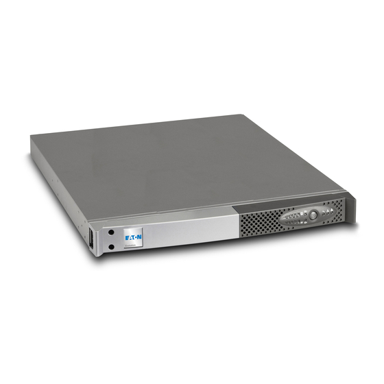
    1. Présentation 1.1 Positions standards Modèles tour Tableau des dimensions (H x L x P) en mm Evolution 650 234 x 147 x 418 Evolution 850 234 x 147 x 418 Evolution 1150 234 x 147 x 418 Evolution 1550 234 x 147 x 492 Tableau des masses en kg Evolution 650...
  • Page 31: Faces Arrières

    1. Présentation 1.2 Faces arrières Evolution 650/850/1150/1550 (1) Emplacement pour carte de communication optionnelle (2) Prise pour le raccordement au réseau électrique d’alimentation 230V/10A Max (3) 2 prises pour le raccordement des équipements Ue/In/Eing (4) Port de communication RS232 (5) 2 prises programmables (1 et 2) pour le raccordement des équipements (6) Port de communication USB (7) Connecteur pour le raccordement...
  • Page 32: Installation

    2. Installation 2.1 Déballage et vérification du contenu (16) ASI Evolution version tour ou version rack. (17) 2 cordons pour raccorder les équipements. (18) Documentation. (19) CD-ROM Solution-Pac. (20) Câble de communication RS232. (21) Câble de communication USB. (22) Kit de montage en armoire 19 pouces (version rack uniquement, sauf 650 Rack).
  • Page 33: Installation Du Modèle Tour

    2. Installation 2.2 Installation du modèle tour 2.3 Installation du modèle rack Suivre les étapes 1 à 4 pour le montage du module sur ses rails. Les rails et le nécessaire de montage sont fournis par EATON. 34008235FR/AC - Page 9...
  • Page 34: Installation Du Modèle 650 Rack

    2. Installation 2.4 Installation du modèle 650 rack Suivre les étapes 1 à 3 pour le montage du module en rack. Le nécessaire de montage est fourni par EATON. 34008235FR/AC - Page 10...
  • Page 35: Ports De Communication

    USB (6) ou RS232 (4) de l’ASI. L'ASI peut désormais dialoguer avec un logiciel d’administration, de personnalisation ou de sécurité EATON. Installation des cartes de communication (en option) Il n'est pas nécessaire d'arrêter l'ASI pour installer la carte de communication : 230V/10A Max Emplacement, à...
  • Page 36: Raccordements Des Équipements

    Pour pouvoir programmer l'arrêt des prises (5) en cours d'autonomie batterie et optimiser ainsi la durée de cette autonomie, il est nécessaire d'avoir accès au logiciel de communication EATON. (1) Caractéristiques du cordon : 250 V - 10 A (section 1mm , type HO5).
  • Page 37: Utilisation

    3. Utilisation 3.1 Mise en service et fonctionnement normal Appuyer sur le bouton (10) environ 1 seconde. Le buzzer émet un bip et tous les voyants s’allument simultanément. Si le réseau électrique d’alimentation est présent : le bouton (10) et le voyant (13) sont allumés : les équipements sont alimentés par le réseau électrique.
  • Page 38: Arrêt De L'asi

    3. Utilisation 3.4 Arrêt de l'ASI Presser le bouton (10) plus de 2 secondes. Les équipements connectés à l’ASI ne sont plus alimentés. 3.5 Utilisation des fonctions de commande à distance de l’ASI Evolution dispose au choix de deux dispositifs de commande à distance.
  • Page 39: Accès Aux Mesures Et Personnalisation

    4. Accès aux mesures et personnalisation Insérer le CD ROM Solution-Pac dans votre lecteur. Sur le premier écran du navigateur, sélectionner "Solution Point à Point" et suivre les instructions pour installer le logiciel Personal Solution-Pac. Sélectionner ensuite "Configuration", puis "Configuration avancée" et "Paramètres onduleur". Noter que les versions Linux/Unix/MacOS du logiciel Personal Solution-Pac n'incluent pas cette possibilité.
  • Page 40: Maintenance

    5. Maintenance 5.1 Dépannage Symptôme Diagnostic Remède Lors du démarrage de l’ASI par le L’action du contact arrêt à Remettre le contact en position bouton (10), tous les voyants distance (RPO) a provoqué l’arrêt normale et appuyer sur le bouton s’allument une fois et le buzzer émet de l’ASI et empêche son (10) pour redémarrer.
  • Page 41: Remontage Du Nouveau Module Batterie

    Remontage du nouveau module batterie Réaliser les opérations décrites ci-dessus en sens inverse. Pour préserver la sécurité et le même niveau de performance, utiliser des éléments batterie fournis par EATON. Veillez à bien enfoncer les parties mâles et femelles du connecteur lors du raccordement.
  • Page 42: Remontage Du Nouveau Module Batterie

    Remontage du nouveau module batterie Réaliser les opérations décrites ci-dessus en sens inverse. Pour préserver la sécurité et le même niveau de performance, utiliser des éléments batterie fournis par EATON. Veillez à bien enfoncer les parties mâles et femelles du connecteur lors du raccordement.
  • Page 43: Annexes

    6. Annexes 6.1 Spécifications techniques Filtre Transformateur Chargeur Onduleur ”AVR” Batterie Evolution 650 / 650 Rack 850 / 850 Rack 1150 / 1150 Rack 1550 / 1550 Rack Puissance de sortie 650 VA / 850 VA / 1150 VA / 1550 VA / 420 W 600 W...
  • Page 44: Glossaire

    6. Annexes 6.2 Glossaire AC Normal Il s’agit du réseau électrique d’alimentation normal de l’ASI. Alimentation Sans Interruption. Autonomie Temps pendant lequel les équipements sont alimentés par l’ASI fonctionnant sur batterie. Décharge Décharge de la batterie au delà de la limite permise occasionnant des dommages profonde irréversibles sur la batterie.
  • Page 45 Notes 34008235FR/AC - Page 21...
  • Page 46 34008235FR/AC...
  • Page 47 Evolution 650/650 Rack 1U 850/850 Rack 1U 1150/1150 Rack 1U 1550/1550 Rack 1U Installations- und Bedienungsanleitung Pulsar Series...
  • Page 48 34008235DE/AC - Page 2...
  • Page 49 Einleitung Wir danken Ihnen, dass Sie sich für ein Produkt von EATON zum Schutz Ihrer Anwendungen entschieden haben. Die Baureihe Evolution wurde mit größter Sorgfalt entwickelt. Um die Leistungen Ihrer USV (Unterbrechungsfreien Stromversorgung) optimal nutzen zu können, empfehlen wir Ihnen, sich ein wenig Zeit zu nehmen und die vorliegende Anleitung aufmerksam zu lesen.
  • Page 50 Allgemeines Bedeutung der Piktogramme Unbedingt zu befolgende Hinweise. Informationen, Ratschläge, Hilfen Optische Anzeige. Maßnahmen, Handlungen. Akustischer Alarm. In den Abbildungen der nachfolgenden Seiten sind die LED-Anzeigen mit folgenden Symbolen dargestellt: LED AUS LED AN LED blinkt 34008235DE/AC - Page 4...
  • Page 51 Inhalt Ansichten und Beschreibung Aufstellvarianten .......................... 6 Tower-Modell..........................6 Rack-Modell ........................... 6 Rückansicht ..........................7 Evolution 650 / 850 / 1150 / 1550 ....................7 Evolution 650 / 850 / 1150 / 1550 ....................7 Bedien- und Anzeigefeld ......................7 Aufstellung und Installation Entfernen der Verpackung und Überprüfung des Lieferumfangs ..........
  • Page 52: Ansichten Und Beschreibung

    1. Ansichten und Beschreibung 1.1 Aufstellvarianten Tower-Modell Abmessungen (H x B x T) in mm Evolution 650 234 x 147 x 418 Evolution 850 234 x 147 x 418 Evolution 1150 234 x 147 x 418 Evolution 1550 234 x 147 x 492 Gewicht in kg Evolution 650 Evolution 850...
  • Page 53: Rückansicht

    1. Ansichten und Beschreibung 1.2 Rückansicht Evolution 650 / 850 / 1150 / 1550 (1) Steckplatz für optionale Kommunikationskarte (2) Netzanschluss (3) 2 normale Ausgangssteckdosen 230V/10A Max (4) RS232-Schnittstelle (5) 2 programmierbare Ue/In/Eing Ausgangssteckdosen (1 und 2) (6) USB-Schnittstelle (7) Steckverbinder für EIN/AUS- Fernbetätigung und NOT-AUS.
  • Page 54: Aufstellung Und Installation

    2. Aufstellung und Installation 2.1 Entfernen der Verpackung und Überprüfung des Lieferumfangs (16) USV Evolution Tower- oder Rack-Modell (17) 2 Verbraucher-Anschlusskabel (18) Dokumentation (19) CD-ROM Solution-Pac (20) RS232-Kabel (21) USB-Kabel (22) Montagekit für Einbau in 19"-Schränke (nur Rack- Modelle, außer Evolution 650 Rack) (23) 2 Verriegelungsabdeckungen für Verbraucher- Anschlusskabel (nur Rack-Modelle) Verpackungen müssen entsprechend den geltenden gesetzlichen Bestimmungen entsorgt werden.
  • Page 55: Aufstellung Des Tower-Modells

    2. Aufstellung und Installation 2.2 Aufstellung des Tower-Modells 2.3 Einbau des Rack-Modells Zur Befestigung des Moduls auf den Teleskopschienen Schritte 1 bis 4 befolgen. Die Teleskopschienen und das benötigte Montagezubehör werden von EATON geliefert. 34008235DE/AC - Page 9...
  • Page 56: Einbau Des Modells Evolution 650 Rack

    2. Aufstellung und Installation 2.4 Einbau des Modells Evolution 650 Rack Zum Einbau des Moduls Schritte 1 bis 3 befolgen. Das benötigte Montagezubehör wird von EATON geliefert. 34008235DE/AC - Page 10...
  • Page 57: Kommunikationsschnittstellen

    (21) oder (20) an die USB-Schnittstelle (6) Us/Out/Ausg I max 6.5A bzw. den RS232-Port (4) der USV anschließen. Die USV kann nun über verschiedene Softwarepakete von EATON mit dem angeschlossenen Rechnersystem kommunizieren (Überwachung, Konfiguration, Sicherheitsparameter). Einbau der optionalen Kommunikationskarten Die Kommunikationskarten können bei eingeschalteter USV installiert werden.
  • Page 58: Anschluss Der Netz- Und Verbraucherkabel

    2. Aufstellung und Installation 2.6 Anschluss der Netz- und Verbraucherkabel Die Kenndaten auf dem Typenschild (siehe Geräte-Rückseite) hinsichtlich ihrer Übereinstimmung mit den vorhandenen Netzparametern und der Leistungsaufnahme aller angeschlossenen Verbraucher überprüfen. 1 - Verbraucher-Netzkabel (nicht mitgeliefert) abziehen. 2 - Abgezogenes Verbraucher-Netzkabel in die Gerätesteckdose (2) der USV und anschließend in die Netzsteckdose einstecken.
  • Page 59: Betriebszustände

    3. Betriebszustände 3.1 Inbetriebnahme und Normalbetrieb Taste (10) etwa 1 Sekunde lang drücken. Der Summer ertönt kurz, und sämtliche LEDs leuchten gleichzeitig auf. Einspeisenetz vorhanden: Die LED der EIN/AUS-Taste (10) und die LED (13) leuchten. Die Verbraucherversorgung erfolgt aus dem Einspeisenetz.
  • Page 60: Abschaltung Der Usv

    3. Betriebszustände 3.4 Abschaltung der USV Taste (10) mehr als 2 Sekunden gedrückt halten. Die an die USV angeschlossenen Systeme werden nicht mehr versorgt. 3.5 Verwendung der Fernbetätigungsfunktionen der USV Evolution arbeitet wahlweise mit zwei Fernbetätigungsvorrichtungen. RPO: Fernabschaltung der USV (Remote Power Off), mit der alle an die USV angeschlossenen Verbraucher durch eine dezentrale Betätigung des Anwenders abgeschaltet werden können.
  • Page 61: Kundenspezifische Anpassung Und Abfrage Der Messwerte

    4. Kundenspezifische Anpassung und Abfrage der Messwerte CD ROM Solution-Pac in das Laufwerk des Rechners einlegen. Auf der ersten Seite des Auswahlmenüs "Solution Schritt für Schritt" auswählen und Anweisungen befolgen, um die Software Personal Solution-Pac zu installieren. Anschließend "Konfiguration" und danach "Erweiterte Konfiguration" und "USV-Einstellungen" auswählen. Achtung: In der Linux/Unix/MacOS-Version der Software Personal Solution-Pac steht diese Auswahloption nicht zur Verfügung.
  • Page 62: Wartung Und Service

    Ausbau des Batteriemoduls Gerät wie abgebildet auf die Seite legen. A - Schrauben auf der linken Gehäuseseite herausdrehen. B - Frontblech mit EATON-Logo nach vorn abziehen. C - Batteriemodul durch Lösen der 2 Steckverbinder abklemmen (nicht an den Kabeln ziehen!).
  • Page 63: Einbau Des Neuen Batteriemoduls

    5. Wartung und Service Einbau des neuen Batteriemoduls Die oben beschriebenen Handgriffe in umgekehrter Reihenfolge ausführen. Zur Gewährleistung der Sicherheit und des Betriebsverhaltens dürfen nur Austauschmodule verwendet werden, die mit den eingebauten Batterien baugleich sind. Es ist sicherzustellen, dass der Batteriestecker vollständig in die zugehörige Buchse des Steckverbinders eingesteckt ist.
  • Page 64: Einbau Des Neuen Batteriemoduls

    5.4 Trainingscenter Um Ihnen eine optimale Betriebsführung Ihrer Anlage sowie eine kompetente Fehleranalyse und -behebung zu ermöglichen, bietet EATON umfangreiche Kundenschulungen in englischer und französischer Sprache an. For further information, please visit our website: www.eaton.com 34008235DE/AC - Page 18...
  • Page 65: Anhang

    6. Anhang 6.1 Technische Daten Filter Trafo Ladegerät Wechselrichter Booster/Fader Batterien Evolution 650 / 650 Rack 850 / 850 Rack 1150 / 1150 Rack 1550 / 1550 Rack 650 VA / 850 VA / 1150 VA / 1550 VA / Ausgangsleistung 420 W 600 W...
  • Page 66: Fachbegriffe

    Inanspruchnahme der Batterie um einen einstellbaren Wert abgesenkt werden kann. Kundenspezifische Programmierung bestimmter Kenndaten durch Änderung der werksseitigen Anpassung Voreinstellungen. Einige Einstellungen können über die USV-Software Personal Solution- Pac von EATON vorgenommen werden. Netz 1 Normales Einspeisenetz der USV. (Gleichrichter) Programmierbare Steckdosen, die bei Batteriebetrieb automatisch abgeworfen werden können...
  • Page 67 Anmerkungen 34008235DE/AC - Page 21...
  • Page 68 34008235DE/AC...
  • Page 69 Evolution 650/650 Rack 1U 850/850 Rack 1U 1150/1150 Rack 1U 1550/1550 Rack 1U Manuale d’installazione e d’utilizzazione Pulsar Series...
  • Page 70 34008235IT/AC - Page 2...
  • Page 71: Tutela Dell'ambiente

    Fine della vita utile La società EATON si è impegnata a trattare i prodotti in fin di vita secondo le regolamentazioni locali. La società EATON lavora con società che si incaricano della raccolta e dell'eliminazione dei nostri prodotti in fin di vita.
  • Page 72: Pittogrammi Utilizzati

    Introduzione Pittogrammi utilizzati Istruzioni da seguire tassativamente. Informazioni, consigli, guida. Indicazione visiva da osservare. Azione da eseguire. Segnalazione acustica. Le convenzioni adottate per rappresentare le spie all’interno delle illustrazioni sono le seguenti: Spia spenta. Spia accesa. Spia lampeggiante. 34008235IT/AC - Page 4...
  • Page 73 Sommario Presentazione Posizioni standard........................6 Modelli tower ..........................6 Modelli rack............................ 6 Vista posteriore ..........................7 Evolution 650/850/1150/1550 ......................7 Evolution 650/850/1150/1550 Rack ....................7 Pannello di visualizzazione e di comando ................. 7 Installazione Apertura dell’imballaggio e verifica del contenuto..............8 Installazione del modello tower ....................
  • Page 74: Presentazione

    1. Presentazione 1.1 Posizioni standard Modelli tower Tabella delle dimensioni (A x L x P) in mm Evolution 650 237 x 147 x 418 Evolution 850 237 x 147 x 418 Evolution 1150 237 x 147 x 418 Evolution 1550 237 x 147 x 492 Tabella dei pesi in kg Evolution 650...
  • Page 75: Vista Posteriore

    1. Presentazione 1.2 Vista posteriore Evolution 650/850/1150/1550 (1) Sede per una scheda di comunicazione opzionale. (2) Presa per il raccordo alla rete elettrica di alimentazione 230V/10A Max (3) 2 prese per il raccordo degli impianti (4) Porta di comunicazione RS232 Ue/In/Eing (5) 2 prese programmabili (1 e 2) per il raccordo degli impianti...
  • Page 76: Installazione

    2. Installazione 2.1 Apertura dell’imballaggio e verifica del contenuto (16) UPS Evolution versione tower o rack. (17) 2 cavi per collegare gli impianti. (18) Documentazione. (19) CD-ROM Solution-Pac. (20) Cavo di comunicazione RS232. (21) Cavo di comunicazione USB. (22) Kit di montaggio all’interno di un armadio rack 19 pollici (solo versione rack, tranne 650 Rack).
  • Page 77: Installazione Del Modello Tower

    2.2 Installazione del modello tower 2.3 Installazione del modello rack Per il montaggio del modulo sulle guide, seguire i passaggi da 1 a 4. Le guide e il materiale necessario per il montaggio sono forniti da EATON. 34008235IT/AC - Page 9...
  • Page 78: Installazione Del Modello 650 Rack

    2. Installazione 2.4 Installazione del modello 650 rack Per il montaggio del modulo nello rack, seguire i passaggi da 1 a 3. Il materiale necessario per il montaggio è fornito da EATON. 34008235IT/AC - Page 10...
  • Page 79: Porte Di Comunicazione

    USB (6) o RS232 (4) dell’UPS. L'UPS è ora in grado di dialogare con un software di amministrazione, di configurazione o di sicurezza EATON. Installazione delle schede di comunicazione (opzione) Non è necessario arrestare il funzionamento dell’UPS per installare una...
  • Page 80 Per poter programmare l’arresto delle prese (5) in fase di autonomia della batteria ed ottimizzare così la durata di tale autonomia, è necessario utilizzare il software di comunicazione EATON. (1) Caratteristiche del cavo: 250 V - 10 A (sezione 1mm , tipo HO5).
  • Page 81: Utilizzo

    3. Utilizzo 3.1 Messa in servizio e funzionamento normale Premere il pulsante (10) per 1 secondo circa. Il cicalino emette un bip e tutte le spie si accendono contemporaneamente. Se la rete elettrica di alimentazione è presente: il pulsante (10) e la spia (13) sono accesi: gli impianti sono alimentati dalla rete elettrica.
  • Page 82: Arresto Dell'ups

    3. Utilizzo 3.4 Arresto dell’UPS Tenere premuto il pulsante (10) per almeno 2 secondi. Gli impianti collegati all’UPS non sono più alimentati. 3.5 Utilizzo delle funzioni di controllo remoto dell’UPS Evolution dispone, a scelta, di due dispositivi di controllo remoto. RPO: si tratta di una funzione di arresto remoto dell’UPS (Remote Power Off) che consente di mettere fuori tensione l’insieme degli impianti collegati all’UPS mediante un contatto di utenza remoto.
  • Page 83: Accesso Alle Misure E Alla Personalizzazione

    4. Accesso alle misure e alla personalizzazione Inserire il CD ROM Solution-Pac nell’apposito lettore. Nella prima schermata del programma che appare, selezionare "Soluzione Punto a Punto" e seguire le istruzioni visualizzate per installare il software Personal Solution-Pac. Selezionare quindi "Configurazione", "Configurazione avanzata" e "Parametri UPS". Tenere presente che le versioni Linux/Unix/MacOS del software Personal Solution-Pac non prevedono questa possibilità...
  • Page 84: Manutenzione

    5. Manutenzione 5.1 Riparazione dei guasti Sintomo Diagnostica Rimedio Durante l’avviamento dell’UPS L’azione del contatto di arresto Riportare il contatto in posizione tramite il pulsante (10), tutte le spie si remoto (RPO) ha provocato normale e premere il pulsante (10) accendono una volta e il cicalino l’arresto dell’UPS e ne impedisce per riavviare l’UPS.
  • Page 85: Rimontaggio Del Nuovo Modulo Batteria

    Rimontaggio del nuovo modulo batteria Ripetere le operazioni sopra descritte in senso inverso. Per preservare la sicurezza e lo stesso livello di performance, utilizzare elementi batteria forniti da EATON. Fare attenzione ad inserire correttamente i componenti maschio e femmina del connettore durante il raccordo.
  • Page 86: Rimontaggio Del Nuovo Modulo Batteria

    Fare attenzione ad inserire correttamente i componenti maschio e femmina del connettore durante il raccordo. 5.4 Centro di formazione Per tenere sotto controllo l’impianto EATON e intervenire al primo livello, viene da noi messo a disposizione dei clienti un programma completo di formazione tecnica in lingua inglese e in lingua francese.
  • Page 87: Allegati

    6. Allegati 6.1 Specifiche tecniche Filtro Stabilizzatore Caricatore ”AVR” Batterie Evolution 650 / 650 Rack 850 / 850 Rack 1150 / 1150 Rack 1550 / 1550 Rack Potenza in uscita 650 VA / 850 VA / 1150 VA / 1550 VA / 420 W 600 W 770 W...
  • Page 88: Glossario

    6. Allegati 6.2 Glossario AC Normale È la rete elettrica di alimentazione normale dell’UPS. Autonomia Periodo di tempo durante il quale gli impianti vengono alimentati dall’UPS funzionante su batteria. Avviamento su Rende possibile la messa sotto tensione degli impianti collegati all'UPS in caso di assenza batteria della rete elettrica di alimentazione.
  • Page 89 Notes 34008235IT/AC - Page 21...
  • Page 90 34008235IT/AC...
  • Page 91 Evolution 650/650 Rack 1U 850/850 Rack 1U 1150/1150 Rack 1U 1550/1550 Rack 1U Manual de instalación y Pulsar Series...
  • Page 92 34008235ES/AC - Page 2...
  • Page 93: Respeto Medioambiental

    Cumplir con las normativas locales vigentes para la eliminación del embalaje. Final de vida útil La sociedad EATON se ha comprometido en tratar los productos al final de su vida útil de acuerdo con lo dispuesto en las normativas locales.
  • Page 94 Introducción Pictogramas utilizados Instrucciones a seguir obligatoriamente Informaciones, consejos, ayuda. Indicación visual de obligatoria observancia Operación a realizar. Señalización acústica. Los símbolos convencionales adoptados para representar los indicadores luminosos en las ilustraciones son los siguientes: Indicador luminoso apagado. Indicador luminoso encendido. Indicador luminoso parpadeando.
  • Page 95 Índice Presentación Posiciones estándar ........................6 Modelos torre ..........................6 Modelos rack ..........................6 Caras traseras..........................7 Evolution 650/850/1150/1550 ......................7 Evolution 650/850/1150/1550 Rack ....................7 Panel de visualización y de mando .................... 7 Instalación Desembalaje y comprobación del contenido ................8 Instalación del modelo de torre ....................
  • Page 96: Presentación

    1. Presentación 1.1 Posiciones estándar Modelos torre Cuadro de dimensiones (A x L x P) en mm Evolution 650 234 x 147 x 418 Evolution 850 234 x 147 x 418 Evolution 1150 234 x 147 x 418 Evolution 1550 234 x 147 x 492 Cuadro de pesos en kg.
  • Page 97: Caras Traseras

    1. Presentación 1.2 Caras traseras Evolution 650/850/1150/1550 (1) Emplazamiento para tarjeta de comunicación opcional (2) Toma para la conexión a la red eléctrica de alimentación 230V/10A Max (3) 2 tomas para la conexión de los equipos Ue/In/Eing (4) Puerto de comunicación RS232 (5) 2 tomas programables (1 y 2) para la conexión de los equipos (6) Puerto de comunicación USB...
  • Page 98: Instalación

    2. Instalación 2.1 Desembalaje y comprobación del contenido (16) SAI Evolution versión torre o versión rack. (17) 2 cables para conectar los equipos. (18) Documentación. (19) CD-ROM Solution-Pac. (20) Cable de comunicación RS232. (21) Cable de comunicación USB. (22) Kit de montaje en armario de 19 pulgadas (solo en la versión rack, excepto 650 Rack).
  • Page 99: Instalación Del Modelo De Torre

    2.2 Instalación del modelo torre 2.3 Instalación del modelo rack Seguir las etapas 1 a 4 para el montaje del módulo sobre sus rieles. Los rieles y el material necesario para el montaje son suministrados por EATON. 34008235ES/AC - Page 9...
  • Page 100: Instalación Del Modelo 650 Rack

    2. Instalación 2.4 Instalación del modelo 650 rack Seguir las etapas 1 a 3 para el montaje del módulo en rack. EATON suministra el material necesario para el montaje. 34008235ES/AC - Page 10...
  • Page 101: Puertos De Comunicación

    USB (6) o RS232 (4) del SAI. El SAI ya podrá dialogar con un software de administración, de personalización o de seguridad EATON. Instalación de las tarjetas de comunicación (opcional) No será necesario parar el SAI para instalar la tarjeta de comunicación:...
  • Page 102: Conexión De Los Equipos

    (5) mientras la batería funciona en modo autónomo y optimizar así la duración de esa autonomía, será necesario tener acceso al software de comunicación EATON. (1) Características del cordón: 250 V - 10 A (sección 1mm , tipo HO5).
  • Page 103: Utilización

    3. Utilización 3.1 Puesta en servicio y en funcionamiento normal Pulsar el botón (10) durante aproximadamente 1 segundo. El buzzer o zumbador emite un bip y todos los indicadores luminosos se encienden simultáneamente. Si la red eléctrica de alimentación está presente: el botón (10) y el indicador luminoso (13) estarán encendidos: los equipos están siendo alimentados por la red eléctrica.
  • Page 104: Parada Del Sai

    3. Utilización 3.4 Parada del SAI Presionar el botón (10) durante más de 2 segundos. Los equipos conectados al SAI ya no están siendo alimentados. 3.5 Utilización de las funciones de mando a distancia del SAI Evolution dispone de dos dispositivos de mando a distancia, según se elija.
  • Page 105: Acceso A Las Medidas Y Personalización

    4. Acceso a las medidas y personalización Insertar el CD ROM Solution-Pac en su lector. En la primera pantalla del navegador, seleccionar "Solución Punto a Punto" y seguir las instrucciones para instalar el software Personal Solution-Pac. A continuación, seleccionar "Configuración" y, luego, "Configuración avanzada" y "Parámetros ondulador". Tener en cuenta que las versiones Linux/Unix/MacOS del software Personal Solution-Pac no incluyen esta posibilidad.
  • Page 106: Mantenimiento

    5. Mantenimiento 5.1 Corrección de anomalías Síntoma Diagnóstico Corrección En el momento de arrancar el SAI con La acción del contacto parada a Volver a poner el contacto en el botón (10), todos los indicadores distancia (RPO) ha provocado la posición normal y pulsar el botón luminosos se encienden una vez y el parada del SAI e impide su...
  • Page 107: Montaje Del Nuevo Módulo De Batería

    Realizar las operaciones descritas más arriba en sentido inverso. Para preservar la seguridad y el mismo nivel de prestaciones, utilizar elementos de batería suministrados por EATON. Procuren acoplar bien hasta el fondo las partes machos y hembras del conector cuando realicen la conexión.
  • Page 108: Montaje Del Nuevo Módulo De Batería

    Procuren acoplar bien hasta el fondo las partes machos y hembras del conector cuando realicen la conexión. 5.4 Centro de formación Para adquirir dominio en la explotación de su aparato EATON e intervenir a primer nivel, ponemos a su disposición un programa completo de formaciones técnicas en inglés y en francés.
  • Page 109: Anexos

    6. Anexos 6.1 Especificaciones técnicas Cargador Ondulador Filtro Transformador ”AVR” Baterias Evolution 650 / 650 Rack 850/850 Rack 1U 1150 / 1150 Rack 1550 / 1550 Rack Potencia de salida 650 VA / 850 VA / 1150 VA / 1550 VA / 420 W 600 W 770 W...
  • Page 110: Glosario

    6. Anexos 6.2 Glosario AC Normal Se trata de la red eléctrica de alimentación normal del SAI. Arranque con batería Permite la puesta en tensión de los equipos conectados al SAI en ausencia de corriente eléctrica de alimentación. El SAI funciona entonces solamente con la batería. Autonomía Tiempo durante el cual los equipos son alimentados por el SAI funcionando con batería.
  • Page 111 Notas 34008235ES/AC - Page 21...
  • Page 112 34008235ES/AC...
  • Page 113 Evolution 650/650 Rack 1U 850/850 Rack 1U 1150/1150 Rack 1U 1550/1550 Rack 1U Installatie- en gebruikershandleiding Pulsar Series...
  • Page 114 34008235NL/AC - Page 2...
  • Page 115: Zorg Voor Het Milieu

    Inleiding Hartelijk dank dat u een van de producten van EATON hebt gekozen voor de beveiliging van uw apparatuur. De Evolution-lijn is met de grootst mogelijke zorg ontwikkeld. Voor een optimaal gebruik van uw UPS (Uninterruptible Power Supply - ononderbroken stroomvoorziening) adviseren wij u om de tijd te nemen en deze handleiding goed te lezen.
  • Page 116: Gebruikte Pictogrammen

    Inleiding Gebruikte pictogrammen Volg deze aanwijzingen altijd op. Informatie, tips, hulp. Handel volgens de zichtbare aanduiding. Voer de aangegeven handeling uit. Geluidssignaal. In deze handleiding wordt het branden van lampjes in de illustraties als volgt aangegeven: Lampje uit. Lampje aan. Knipperend lampje.
  • Page 117 Inhoud Beschrijving Standaardopstellingen ........................ 6 Towermodellen ..........................6 Rackmodellen..........................6 Achterkant ............................ 7 Evolution 650/850/1150/1550 ......................7 Evolution 650/850/1150/1550 Rack ....................7 Bedieningspaneel......................... 7 Installatie Uitpakken en controle van de inhoud ..................8 Plaatsen van het towermodel ..................... 9 Plaatsen van het rackmodel......................9 Plaatsen van rackmodel 650 .....................10 Communicatiepoorten .......................11 Aansluiten van de RS232- of USB-communicatiepoort (facultatief) ..........11...
  • Page 118: Beschrijving

    1. Beschrijving 1.1 Standaardopstellingen Towermodellen Overzicht afmetingen (H x B x D) in mm Evolution 650 234 x 147 x 418 Evolution 850 234 x 147 x 418 Evolution 1150 234 x 147 x 418 Evolution 1550 234 x 147 x 492 Overzicht gewichten in kg Evolution 650 Evolution 850...
  • Page 119: Achterkant

    1. Beschrijving 1.2 Achterkant Evolution 650/850/1150/1550 (1) Plaats voor optionele communicatiekaart (2) Aansluiting voor het elektrische voedingsnet 230V/10A Max (3) 2 aansluitingen voor apparatuur (4) RS232-communicatiepoort Ue/In/Eing (5) 2 instelbare aansluitingen (1 en 2) voor apparatuur (6) USB-communicatiepoort (7) Connector voor aansluiting van een Remote On/Off en een noodstop.
  • Page 120: Uitpakken En Controleren Van De Inhoud

    2. Plaatsing 2.1 Uitpakken en controleren van de inhoud (16) Ups van het type Evolution in tower- of rackuitvoering. (17) 2 snoeren voor het aansluiten van de apparatuur. (18) Documentatie. (19) Solution-Pac-cd-rom. (20) RS232 communicatiekabel. (21) USB-communicatiekabel. (22) Montageset voor een 19 inch kast (alleen rackuitvoering behalve 650 Rack).
  • Page 121: Installatie

    2.2 Plaatsen van het towermodel 2.3 Plaatsen van het rackmodel Volg de stappen 1 tot en met 4 voor het monteren van de module op zijn rails. De rails en de montagebenodigdheden worden geleverd door EATON. 34008235NL/AC - Page 9...
  • Page 122: Plaatsen Van Rackmodel 650

    2. Plaatsing 2.4 Plaatsen van rackmodel 650 Volg de stappen 1 tot en met 3 om de module in een rack te monteren. Het montagemateriaal wordt door EATON geleverd. 34008235NL/AC - Page 10...
  • Page 123: Communicatiepoorten

    USB-communicatiepoort (6) of de RS232- communicatiepoort (4) van de UPS. De UPS kan nu communiceren met besturings-, configuratie- of beveiligingssoftware van EATON. Installatie van communicatiekaarten (optie) De UPS hoeft niet te worden uitgeschakeld om de communicatiekaart te installeren: 230V/10A Max...
  • Page 124: Aansluiten Van Apparatuur

    EATON. (1) Eigenschappen van het snoer: 250 V - 10 A (dikte 1mm , type HO5). Breng het bevestigingssysteem voor de kabels aan. (alleen "rack"-uitvoering) 4 - Borg de aansluitingen door middel van het kabelklemsysteem (23).
  • Page 125: Gebruik

    3. Gebruik 3.1 Ingebruikname en normaal bedrijf Druk gedurende ongeveer 1 seconde op toets (10). De zoemer geeft een geluidssignaal en alle lampjes gaan tegelijk branden. Wanneer het elektriciteitsnet in werking is toets (10) en lampje (13) branden: de apparatuur wordt gevoed door het elektriciteitsnet. Als de omstandigheden het toelaten, voert de UPS een accutest uit.
  • Page 126: Uitschakelen Van De Ups

    3. Gebruik 3.4 Uitschakelen van de UPS Druk langer dan 2 seconden op toets (10). De op de UPS aangesloten apparatuur wordt niet meer gevoed. 3.5 Gebruik van de functies voor afstandsbediening van de UPS Evolution beschikt naar keuze over twee voorzieningen voor afstandsbediening.
  • Page 127: Toegang Tot Metingen En Instellingen

    4. Toegang tot metingen en instellingen Plaats de Solution-Pac-CD-ROM in de CD-speler. Kies in het eerste venster van de browser "Solution Point à Point" (stapsgewijze oplossing) en volg de aanwijzingen om de Personal Solution-Pac-software te installeren. Kies vervolgens "Configuration" (configuratie) en dan "Configuration avancée" (geavanceerd) en "Paramètres onduleur"...
  • Page 128: Onderhoud

    5. Onderhoud 5.1 Verhelpen van storingen Probleem Oorzaak Oplossing Bij het opstarten van de UPS met Het op afstand bediende Zet het contact terug in de normale toets (10) gaan alle lampjes een keer uitschakelcontact (RPO) heeft de stand en druk op toets (10) om de branden en geeft de zoemer een UPS uitgeschakeld en voorkomt UPS weer op te starten.
  • Page 129: Veiligheidsvoorschriften

    5. Onderhoud Plaatsen van de nieuwe accumodule Voer bovenstaande handelingen in omgekeerde volgorde uit. Gebruik met het oog op de veiligheid en optimale prestaties alleen accu-elementen die door EATON worden geleverd. Druk bij het aansluiten de connectoren goed in elkaar.
  • Page 130: Trainingscentrum

    Druk bij het aansluiten de connectoren goed in elkaar. 5.4 Trainingscentrum Om volledig vertrouwd te raken met het gebruik van uw toestel van EATON en om op het hoogste niveau problemen te kunnen verhelpen, bieden wij u een compleet programma met technische trainingen aan. Deze worden in het Engels en het Frans gegeven.
  • Page 131: Bijlagen

    Bijlagen 6.1 Technische gegevens Filter Transformator Lader Wisselrichter ”AVR” Accu’s Evolution 650 / 650 Rack 850 / 850 Rack 1150 / 1150 Rack 1550 / 1550 Rack Uitgangsvermogen 650 VA / 850 VA / 1150 VA / 1550 VA / 420 W 600 W 770 W...
  • Page 132: Definities

    6. Bijlagen 6.2 Definities AC Normal Dit is het elektriciteitsnet waarmee de UPS onder normale omstandigheden wordt gevoed. Accutest Interne test van de UPS om de toestand van de accu te controleren. Accutijd De tijd gedurende welke de apparatuur wordt gevoed door de UPS die op accubedrijf draait.
  • Page 133 Notes 34008235NL/AC - Page 21...
  • Page 134 34008235NL/AC...
  • Page 135 Pulsar Series...
  • Page 137 EATON EATON EATON EATON EATON...
  • Page 143 EATON...
  • Page 144 EATON...
  • Page 145 EATON...
  • Page 146 EATON...
  • Page 151 EATON.
  • Page 152 EATON. EATON eaton...
  • Page 156 eaton...
  • Page 157 3400823500/AC...
  • Page 158 3400823500/AC...

Table des Matières