Eaton Evolution Pulsar Serie Manuel D'installation Et D'utilisation
Masquer les pouces Voir aussi pour Evolution Pulsar Serie:
Table des Matières

Publicité

Les langues disponibles
  • FR

Les langues disponibles

  • FRANÇAIS, page 27

Liens rapides

www.eaton.com
Pulsar Series
Evolution
S 1250 RT 2U
S 1750 RT 2U
2000 RT 2U
S 2500 RT 2U
S 3000 RT 2U
S 3000 RT 3U
S EXB 1250/1750 RT 2U
S EXB 2500/3000 RT 2U
S EXB 2500/3000 RT 3U
Installation and user
manual
English
Français
Deutsch
Italiano
Español
Nederlands

Publicité

Table des Matières
loading

Sommaire des Matières pour Eaton Evolution Pulsar Serie

  • Page 1 Evolution S 1250 RT 2U S 1750 RT 2U 2000 RT 2U S 2500 RT 2U S 3000 RT 2U S 3000 RT 3U S EXB 1250/1750 RT 2U S EXB 2500/3000 RT 2U S EXB 2500/3000 RT 3U...
  • Page 2 3400823600/AC...
  • Page 3 Evolution S 1250 RT 2U S 1750 RT 2U 2000 RT 2U S 2500 RT 2U S 3000 RT 2U S 3000 RT 3U S EXB 1250/1750 RT 2U S EXB 2500/3000 RT 2U S EXB 2500/3000 RT 3U...
  • Page 4 34008236EN/AC - Page 2...
  • Page 5: Environmental Protection

    Before installing Evolution, please read the booklet presenting the safety instructions. Then follow the indications in this manual. To discover the entire range of EATON products and the options available for the Evolution range, we invite you to visit our web site at www.eaton.com or contact your EATON representative.
  • Page 6 Introduction Pictograms Important instructions that must always be followed. Information, advice, help. Visual indication. Action. Audio signal. In the illustrations on the following pages, the symbols below are used: LED off LED on LED flashing 34008236EN/AC - Page 4...
  • Page 7: Table Des Matières

    Contents Presentation Standard positions ........................6 Tower position..........................6 Rack position..........................6 Rear panels ........................... 7 Evolution 2500 / 3000 ........................7 Evolution 1250 / 1750 / 2000 ......................7 Evolution EXB (optional battery module)..................7 Control panel..........................7 Installation Unpacking and contents check....................
  • Page 8: Presentation

    1. Presentation 1.1 Standard positions Tower position Dimensions (W x H x D) in mm S 1250 RT 2U 440 x 86 x 509 S 1750 RT 2U 2000 RT 2U S 2500 RT 2U 440 x 86 x 634 S 3000 RT 2U S 3000 RT 3U 440 x 131 x 484...
  • Page 9: Rear Panels

    1. Presentation 1.2 Rear panels Evolution S 2500 / S 3000 (1) USB communication port (2) RS232 communication port (3) Connector for automatic recognition of an additional battery module (4) Slot for optional communication card (5) Connector for ROO (remote ON/OFF) or RPO (Remote Power Off) control (6) Connector for additional battery module (except Evolution 2000)
  • Page 10: Installation

    2. Installation 2.1 Unpacking and contents check (30) Evolution UPS Elements supplied depending on the version or optional (31) connection cable to AC-power source (Evolution (39) 2 supports for the upright position (RT 2U version S 2500 and S 3000 models only) only) (32) 2 connection cables for the protected equipment (40) FlexPDU module (optional)
  • Page 11: Installation In Tower Position

    2.3 Installation in rack position It is advised to first install the battery module, then the power module above. Follow steps 1 to 4 for module mounting on the rails. The rails and necessary hardware are supplied by EATON. 34008236EN/AC - Page 9...
  • Page 12: Communication Ports

    USB (1) or RS232 (2) communication port on the UPS. The UPS can now communicate with EATON power management software. Installation of the communication cards (optional, standard on the Netpack versions) It is not necessary to shutdown the UPS before installing a communication card.
  • Page 13: Connection With A Flexpdu (Power Distribution Unit) Module (Optional)

    2. Installation 2.5 Connection with a FlexPDU (Power Distribution Unit) module (optional) 1 - Evolution S 2500 / S 3000: connect the UPS input socket (10) to the AC-power Evolution S 2500 / S 3000 source using the cable (31) supplied. Evolution S 1250 / S 1750 / 2000: use the power cable of the protected equipment.
  • Page 14: Hotswap Mbp Module Operation

    A outlet (7). To program shutdown of outlets (8) during operation on battery power and thus optimise the available backup time, the EATON communication software is required. 3 - Fit the connection securing system (35) that prevents the plugs from being pulled out accidentally.
  • Page 15: Operation

    3. Operation 3.1 Start-up and normal operation Press button (24) for approximately 1 second. The buzzer beeps once and all the LEDs go ON simultaneously. If AC input power is available, button (24) and LED (25) are ON. The load is supplied by the AC-power source. Conditions permitting, the UPS runs a battery test, indicated by LEDs (21) and the buzzer.
  • Page 16: Return Of Ac Input Power

    3. Operation End of battery backup time All the LEDs go OFF. The audio alarms stops. The UPS is completely shut down. 3.3 Return of AC input power Following an outage, the UPS restarts automatically when AC input power returns (unless the restart function has been disabled via UPS personalisation) and the load is again supplied.
  • Page 17 3. Operation Contact open: UPS shutdown Contact closed: UPS start-up (UPS connected to AC power and AC power is available) Note. The local ON/OFF control using button (24) overrides the remote-control function. Contact open: UPS shutdown, LED (26) goes ON. To return to normal operation, deactivate the remote external contact and restart the UPS by pressing button (24).
  • Page 18: Personalisation Using External Software

    4. Personalisation using external software Insert the Solution-Pac CD-ROM in the drive. On the first navigation screen, select "Point to Point solution" and follow the instructions on how to install the Personal Solution-Pac software. Then select "Settings", "Advanced settings" and "UPS settings". Note that the Linux/Unix/MacOS versions of Personal Solution-Pac software do not offer this possibility.
  • Page 19: Maintenance

    5. Maintenance 5.1 Troubleshooting Indication Diagnostic Correction When the UPS is started using button The remote power off (RPO) Set the contact back to its normal (24), all the LEDs go ON once and the contact has been activated to shut position and press button (24) to buzzer beeps once, then LED (26) down the UPS and now prevents...
  • Page 20: Battery-Module Replacement

    5. Maintenance 5.2 Battery-module replacement Safety recommendations The battery can cause electrocution and high short-circuit currents. The following safety precautions are required before servicing the battery components: Remove watches, rings, bracelets and all other metal objects from the hands and arms, Use tools with an insulated handle.
  • Page 21: Mounting The New Battery Module

    OFF. 5.4 Training centre To fully master operation of your EATON product and carry out level 1 servicing, see our complete range of technical training courses, available in both French and English. For further information, please visit our website: www.eaton.com...
  • Page 22: Appendices

    6. Appendices 6.1 Technical specifications Transformer Charger Filter Inverter (AVR) Battery Evolution S Evolution S Evolution Evolution S Evolution S 1250 1750 2000 2500 3000 Output power 1250VA/1150W 1750VA/1600W 2000VA/1600W 2500VA/2250W 3000VA/2700W AC input power Rated input voltage Single phase 220~240 V Input-voltage range 160 V to 294 V Input-frequency range...
  • Page 23: Glossary

    6. Appendices 6.2 Glossary Backup time Time during which the load can be supplied by the UPS operating on battery power. Battery test Internal UPS test to check battery status. Booster mode Automatic UPS mode that steps up the AC voltage if it is too low, to a level above the personalised set-point, without discharging the battery.
  • Page 24 34008236EN/AC...
  • Page 25 Evolution S 1250 RT 2U S 1750 RT 2U 2000 RT 2U S 2500 RT 2U S 3000 RT 2U S 3000 RT 3U S EXB 1250/1750 RT 2U S EXB 2500/3000 RT 2U S EXB 2500/3000 RT 3U Manuel d’installation et...
  • Page 26 34008236FR/AC - Page 2...
  • Page 27: Respect De L'environnement

    Avant l’installation de Evolution, lire le livret qui présente les consignes de sécurité à respecter. Suivre ensuite les instructions du présent manuel. Nous vous invitons à découvrir l'offre de EATON ainsi que les options de la gamme Evolution en visitant notre site WEB : www.eaton.com, ou en contactant votre représentant EATON.
  • Page 28: Pictogrammes Utilisés

    Introduction Pictogrammes utilisés Consignes à suivre impérativement. Informations, conseils, aide. Indication visuelle à observer. Action à réaliser. Signalisation sonore. Les conventions adoptées pour représenter les voyants dans les illustrations sont les suivantes : Voyant éteint. Voyant allumé. Voyant clignotant. 34008236FR/AC - Page 4...
  • Page 29 Sommaire Présentation Positions standards ........................6 Position tour ........................... 6 Position rack ........................... 6 Faces arrières ..........................7 Evolution 2500 / 3000 ........................7 Evolution 1250 / 1750 / 2000 ......................7 Evolution EXB (module batterie optionnel)..................7 Panneau d'affichage et de commande ..................7 Installation Déballage et vérification du contenu ..................
  • Page 30: Présentation

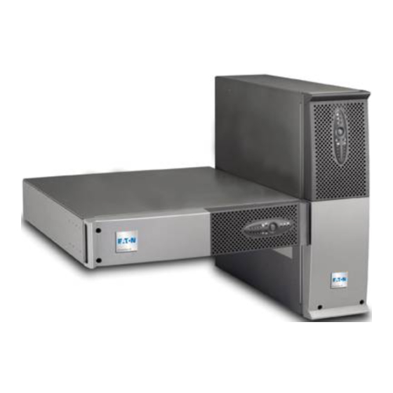
    1. Présentation 1.1 Positions standards Position tour Tableau des dimensions (L x H x P) en mm S 1250 RT 2U 440 x 86 x 509 S 1750 RT 2U 2000 RT 2U S 2500 RT 2U 440 x 86 x 634 S 3000 RT 2U S 3000 RT 3U 440 x 131 x 484...
  • Page 31: Faces Arrières

    1. Présentation 1.2 Faces arrières Evolution S 2500 / S 3000 (1) Port de communication USB (2) Port de communication RS232 (3) Connecteur de reconnaissance automatique d’un module batterie supplémentaire (4) Emplacement pour carte de communication optionnelle. (5) Connecteur pour le raccordement d’une commande Marche/Arrêt distante ou d’un arrêt d’urgence ROO (Remote ON/ OFF).
  • Page 32: Installation

    2. Installation 2.1 Déballage et vérification du contenu (30) ASI Evolution. Eléments fournis selon la version ou en option : (31) Cordon de raccordement au réseau électrique (39) 2 Pieds de maintien en position verticale (version RT (modèles Evolution S 2500 et S 3000 uniquement). 2U seulement).
  • Page 33: Installation En Position Tour

    Il est recommandé de monter le module batterie en premier, puis de monter le module de puissance au-dessus. Suivre les étapes 1 à 4 pour le montage du module sur ses rails. Les rails et le nécessaire de montage sont fournis par EATON. 34008236FR/AC - Page 9...
  • Page 34: Ports De Communication

    L'ASI peut désormais dialoguer avec un logiciel d’administration, de personnalisation ou de sécurité EATON. Installation des cartes de communication (option, en standard pour les versions Netpack) Il n'est pas nécessaire d'arrêter l'ASI pour installer la carte de communication : Emplacement, à...
  • Page 35: Raccordements Avec Un Module Flexpdu (Power Distribution Unit)

    2. Installation 2.5 Raccordements avec un module FlexPDU (Power Distribution Unit) (Option) 1 - Evolution S 2500 / S 3000 : relier la prise d’entrée (10) de l’ASI au réseau Evolution S 2500 / S 3000 électrique à l’aide du cordon (31) fourni. Evolution S 1250 / S 1750 / 2000 : utiliser le cordon d’alimentation de l’équipement à...
  • Page 36: Fonctionnement Du Module Hotswap Mbp

    (8) en cours d'autonomie batterie et optimiser ainsi la durée de cette autonomie, il est nécessaire d'avoir accès au logiciel de communication EATON. 3 - Verrouiller le raccordement en fixant le système de maintien des câbles (35). Nota : l’appareil recharge sa batterie dès qu’il est raccordé au réseau électrique, même sans appuyer sur le bouton (24).
  • Page 37: Utilisation

    3. Utilisation 3.1 Mise en service et fonctionnement normal Appuyer sur le bouton (24) environ 1 seconde. Le buzzer émet un bip et tous les voyants s’allument simultanément. Si le réseau électrique d’alimentation est présent : le bouton (24) et le voyant (25) sont allumés : les équipements sont alimentés par le réseau électrique.
  • Page 38: Retour Du Réseau Électrique

    3. Utilisation Fin d'autonomie batterie Tous les voyants sont éteints. L’alarme sonore est silencieuse. L'ASI est arrêtée complètement. 3.3 Retour du réseau électrique Après la coupure, l'ASI redémarre automatiquement au retour du réseau électrique (à moins que cette fonction n'ait été...
  • Page 39 3. Utilisation Contact ouvert : arrêt de l’ASI Contact fermé : mise en marche de l’ASI (ASI raccordée au réseau et réseau présent) Nota : la commande Marche/Arrêt locale par le bouton (24) reste prioritaire par rapport à la commande à distance. Contact ouvert : arrêt de l’ASI, le voyant (26) s’allume.
  • Page 40: Personnalisation Par Logiciel Externe

    4. Personnalisation par logiciel externe Insérer le CD ROM Solution-Pac dans votre lecteur. Sur le premier écran du navigateur, sélectionner "Solution Point à Point" et suivre les instructions pour installer le logiciel Personal Solution-Pac. Sélectionner ensuite "Configuration", puis "Configuration avancée" et "Paramètres onduleur". Noter que les versions Linux/Unix/MacOS du logiciel Personal Solution-Pac n'incluent pas cette possibilité.
  • Page 41: Maintenance

    5. Maintenance 5.1 Dépannage Symptôme Diagnostic Remède Lors du démarrage de l’ASI par le L’action du contact arrêt à Remettre le contact en position bouton (24), tous les voyants distance (RPO) a provoqué l’arrêt normale et appuyer sur le bouton s’allument une fois et le buzzer émet de l’ASI et empêche son (24) pour redémarrer.
  • Page 42: Remplacement Du Module Batterie

    5. Maintenance 5.2 Remplacement du module batterie Rappel sur les consignes de sécurité : La batterie présente un risque d'électrocution et un courant de court-circuit élevé. Les précautions suivantes doivent être prises pour toute intervention sur les éléments batterie : Oter des mains montres, bagues, alliances, bracelets ou tout autre objet métallique, Utiliser des outils dont le manche est isolé.
  • Page 43: Remontage Du Nouveau Module Batterie

    Remontage du nouveau module batterie Réaliser les opérations décrites ci-dessus en sens inverse. Pour préserver la sécurité et le même niveau de performance, utiliser des éléments batterie fournis par EATON. Veillez à bien enfoncer les parties mâles et femelles du connecteur lors du raccordement.
  • Page 44: Annexes

    6. Annexes 6.1 Spécifications techniques Transformateur Chargeur Filtre Onduleur Batteries Evolution S Evolution S Evolution Evolution S Evolution S 1250 1750 2000 2500 3000 Puissance de sortie 1250VA/1150W 1750VA/1600W 2000VA/1600W 2500VA/2250W 3000VA/2700W Réseau électrique d’alimentation Tension d’entrée nominale Monophasée 220~240 V Plage de tension d’entrée de 160 V à...
  • Page 45: Glossaire

    6. Annexes 6.2 Glossaire AC By-pass Voie dérivée du réseau électrique d’alimentation, commandée par l’ASI et permettant une alimentation directe des équipements par le réseau électrique en cas de surcharge ou de dysfonctionnement de l’onduleur. AC Normal Il s’agit du réseau électrique d’alimentation normal de l’ASI. Alimentation Sans Interruption.
  • Page 46 34008236FR/AC...
  • Page 47 Evolution S 1250 RT 2U S 1750 RT 2U 2000 RT 2U S 2500 RT 2U S 3000 RT 2U S 3000 RT 3U S EXB 1250/1750 RT 2U S EXB 2500/3000 RT 2U S EXB 2500/3000 RT 3U...
  • Page 48 34008236DE/AC - Page 2...
  • Page 49 Einleitung Wir danken Ihnen, dass Sie sich für ein Produkt von EATON zum Schutz Ihrer Anwendungen entschieden haben. Die Baureihe Evolution wurde mit größter Sorgfalt entwickelt. Um die Leistungen Ihrer USV (Unterbrechungsfreien Stromversorgung) optimal nutzen zu können, empfehlen wir Ihnen, sich ein wenig Zeit zu nehmen und die vorliegende Anleitung aufmerksam zu lesen.
  • Page 50 Allgemeines Bedeutung der Piktogramme Unbedingt zu befolgende Hinweise. Informationen, Ratschläge, Hilfen. Optische Anzeige. Maßnahmen, Handlungen. Akustischer Alarm. In den Abbildungen der nachfolgenden Seiten sind die LED-Anzeigen mit folgenden Symbolen dargestellt: LED AUS LED AN LED blinkt 34008236DE/AC - Page 4...
  • Page 51 Inhalt Ansichten und Beschreibung Aufstellvarianten .......................... 6 Tower-Aufstellung........................... 6 Rack-Einbau............................ 6 Rückansicht ..........................7 Evolution 2500 / 3000 ........................7 Evolution 1250 / 1750 / 2000 ......................7 Evolution EXB (Batterie-Erweiterungsmodul)................. 7 Bedien- und Anzeigefeld ......................7 Aufstellung und Installation Entfernen der Verpackung und Überprüfung des Lieferumfangs ..........
  • Page 52: Ansichten Und Beschreibung

    1. Ansichten und Beschreibung 1.1 Aufstellvarianten Tower-Aufstellung Abmessungen (B x H x T) in mm S 1250 RT 2U 440 x 86 x 509 S 1750 RT 2U 2000 RT 2U S 2500 RT 2U 440 x 86 x 634 S 3000 RT 2U S 3000 RT 3U 440 x 131 x 484...
  • Page 53: Rückansicht

    1. Ansichten und Beschreibung 1.2 Rückansicht Evolution S 2500 / S 3000 (1) USB-Schnittstelle (2) RS232-Schnittstelle (3) Stecker zur automatischen Erkennung eines externen Batteriemoduls (4) Steckplatz für optionale Kommunikationskarte. (5) Steckverbinder für EIN/AUS- Fernbetätigung oder NOT-AUS. (6) Steckverbinder zum Anschluss eines externen Batteriemoduls (außer Evolution 2000) (7) 16A-Ausgangssteckdose...
  • Page 54: Aufstellung Und Installation

    2. Aufstellung und Installation 2.1 Entfernen der Verpackung und Überprüfung des Lieferumfangs (30) USV Evolution. Lieferbestandteile je nach Version und Optionen (31) Netzkabel (nur bei Modellen Evolution S 2500 (39) 2 Stützfüße für Toweraufstellung (nur für Modelle RT und S 3000. 2U).
  • Page 55: Aufstellung Des Tower-Modells

    2.3 Einbau des Rack-Modells Es sollte zunächst das Batteriemodul und anschließend das USV-Modul darüber montiert werden. Zur Befestigung des Moduls auf den Teleskopschienen Schritte 1 bis 4 befolgen. Die Teleskopschienen und das benötigte Montagezubehör werden von EATON geliefert. 34008236DE/AC - Page 9...
  • Page 56: Kommunikationsschnittstellen

    2 - Das jeweils andere Ende des Kabels (34) oder (33) an die USB-Schnittstelle (1) bzw. den RS232-Port (2) der USV anschließen. Die USV kann nun über verschiedene Softwarepakete von EATON mit dem angeschlossenen Rechnersystem kommunizieren (Überwachung, Konfiguration, Sicherheitsparameter). Einbau der Kommunikationskarten (Option, Standard bei Netpack-Modellen) Die Kommunikationskarten können bei...
  • Page 57: Usv-Anschluss Mit Optionalem Flexpdu-Installationsverteiler (Power Distribution Unit)

    2. Aufstellung und Installation 2.5 USV-Anschluss mit optionalem FlexPDU-Installationsverteiler (Power Distribution Unit) 1 - Evolution S 2500 / S 3000: Eingangssteckdose (10) der USV über das Evolution S 2500 / S 3000 mitgelieferte Netzkabel (31) mit dem Versorgungsnetz verbinden. Evolution S 1250 / S 1750 / 2000: Netzkabel des zu schützenden Gerätes verwenden.
  • Page 58: Funktionsweise Des Hotswap-Mbp-Moduls

    2. Aufstellung und Installation Funktionsweise des HotSwap-MBP-Moduls An der Rückseite des HotSwap-MBP- Moduls befindet sich ein Drehschalter (53) mit 2 Schaltstellungen: Stellung Normal: Die Verbraucherversorgung erfolgt über die USV. Stellung By-pass: Die Verbraucherversorgung erfolgt aus dem Einspeisenetz. Einschalten der USV bei Verwendung des HotSwap-MBP-Moduls: 1 - Korrekten Anschluss der USV an das HotSwap-MBP-Modul überprüfen.
  • Page 59: Betriebszustände

    3. Betriebszustände 3.1 Inbetriebnahme und Normalbetrieb Taste (24) etwa 1 Sekunde lang drücken. Der Summer ertönt kurz, und sämtliche LEDs leuchten gleichzeitig auf. Einspeisenetz vorhanden: Die LED der EIN/AUS-Taste (24) und die LED (25) leuchten. Die Verbraucherversorgung erfolgt aus dem Einspeisenetz.
  • Page 60: Rückkehr Der Netzspannung

    3. Betriebszustände Abschaltung am Ende der Autonomiezeit Alle LEDs sind aus. Der Summer gibt keinen Ton ab. Die USV ist vollständig abgeschaltet. 3.3 Rückkehr der Netzspannung Bei Netzrückkehr nach einer Abschaltung erfolgt ein automatischer Neustart der USV, sofern die Funktion nicht durch kundenspezifische Anpassung deaktiviert wurde.
  • Page 61 3. Betriebszustände Kontakt geöffnet: Abschaltung der USV. Kontakt geschlossen: Einschalten der USV (Voraussetzung: USV ist an das Netz angeschlossen und Netzspannung ist vorhanden). Hinweis: Die EIN/AUS-Funktion (24) am Gerät ist vorrangig gegenüber der Fernbetätigung. Kontakt geöffnet: Abschaltung der USV, LED (26) leuchtet auf. Zur Rückkehr in den Normalbetrieb externen Fernabschaltkontakt zurücksetzen und USV mit der EIN/AUS-Taste (24) am Gerät wieder einschalten.
  • Page 62: Kundenspezifische Anpassung Über Externe Software

    4. Kundenspezifische Anpassung über externe Software CD ROM Solution-Pac in das Laufwerk des Rechners einlegen. Auf der ersten Seite des Auswahlmenüs "Solution Schritt für Schritt" auswählen und Anweisungen befolgen, um die Software Personal Solution-Pac zu installieren. Anschließend "Konfiguration" und danach "Erweiterte Konfiguration" und "USV-Einstellungen" auswählen. Achtung: In der Linux/Unix/MacOS-Version der Software Personal Solution-Pac steht diese Auswahloption nicht zur Verfügung.
  • Page 63: Wartung Und Service

    5. Wartung und Service 5.1 Fehlerbehebung Fehleranzeige Fehlerursache Fehlerbehebung Beim Einschalten der USV mit dem Die USV wurde durch den Fernbetätigungskontakt Ein/Aus-Taster (24) leuchten alle Fernbetätigungskontakt (RPO) zurücksetzen und anschließend LEDs auf und der Summer ertönt abgeschaltet und lässt sich nicht USV mit der EIN/AUS-Taste (24) kurz;...
  • Page 64: Austausch Des Batteriemoduls

    5. Wartung und Service 5.2 Austausch des Batteriemoduls Sicherheitsmaßnahmen: Die Batterie hat einen hohen Kurzschlussstrom und kann Stromschläge verursachen. Bei jeder Handhabung der Batterien sind daher folgende Sicherheitsmaßnahmen einzuhalten: Armbanduhren, Ringe, Armreifen und sonstige an Händen oder Armen getragene Metallgegenstände abnehmen. Werkzeuge mit Isoliergriff verwenden.
  • Page 65: Einbau Des Neuen Batteriemoduls

    HotSwap-MBP-Modul erlischt. 5.4 Trainingscenter Um Ihnen eine optimale Betriebsführung Ihrer Anlage sowie eine kompetente Fehleranalyse und -behebung zu ermöglichen, bietet EATON umfangreiche Kundenschulungen in englischer und französischer Sprache an. For further information, please visit our website: www.eaton.com 34008236DE/AC - Page 19...
  • Page 66: Anhang

    6. Anhang 6.1 Technische Daten Trafo Ladegerät Filter Wechselrichter Booster/Fader Batterien Evolution S Evolution S Evolution Evolution S Evolution S 1250 1750 2000 2500 3000 Ausgangsleistung 1250VA/1150W 1750VA/1600W 2000VA/1600W 2500VA/2250W 3000VA/2700W Einspeisenetz Eingangsspannung Einphasennetz 220~240 V Eingangsspannungsbereich 160 - 294 V Eingangsfrequenzbereich 47 - 70 Hz (50-Hz-Netz) bzw.
  • Page 67: Fachbegriffe

    Programmierung bestimmter Kenndaten durch Änderung der werksseitigen Anpassung Voreinstellungen. Einige Einstellungen können über die USV-Software Personal Solution- Pac von EATON vorgenommen werden. Netz 2 (Bypass) Ersatzeinspeisung, die eine Umgehung des Wechselrichters durch Umschaltung auf den NRE-Zweig im Überlastfall sowie eine Freischaltung bei Wartung oder Störung der USV erlaubt.
  • Page 68 34008236DE/AC...
  • Page 69 Evolution S 1250 RT 2U S 1750 RT 2U 2000 RT 2U S 2500 RT 2U S 3000 RT 2U S 3000 RT 3U S EXB 1250/1750 RT 2U S EXB 2500/3000 RT 2U S EXB 2500/3000 RT 3U Manuale d’installazione e...
  • Page 70 34008236IT/AC - Page 2...
  • Page 71: Tutela Dell'ambiente

    Fine della vita utile La società EATON si è impegnata a trattare i prodotti in fin di vita secondo le regolamentazioni locali. La società EATON lavora con società che si incaricano della raccolta e dell'eliminazione dei nostri prodotti in fin di vita.
  • Page 72: Pittogrammi Utilizzati

    Introduzione Pittogrammi utilizzati Istruzioni da seguire tassativamente. Informazioni, consigli, guida. Indicazione visiva da osservare. Azione da eseguire. Segnalazione acustica. Le convenzioni adottate per rappresentare le spie all'interno delle illustrazioni sono le seguenti: Spia spenta. Spia accesa. Spia lampeggiante. 34008236IT/AC - Page 4...
  • Page 73 Sommario Presentazione Posizioni standard........................6 Posizione tower..........................6 Posizione rack ..........................6 Vista posteriore ..........................7 Evolution 2500 / 3000 ........................7 Evolution 1250 / 1750 / 2000 ......................7 Evolution EXB (modulo batteria opzionale)..................7 Pannello di visualizzazione e di comando ................. 7 Installazione Apertura dell’imballaggio e verifica del contenuto..............
  • Page 74: Presentazione

    1. Presentazione 1.1 Posizioni standard Posizione tower Tabella delle dimensioni (A x L x P) in mm S 1250 RT 2U 440 x 86 x 509 S 1750 RT 2U 2000 RT 2U S 2500 RT 2U 440 x 86 x 634 S 3000 RT 2U S 3000 RT 3U 440 x 131 x 484...
  • Page 75: Vista Posteriore

    1. Presentazione 1.2 Vista posteriore Evolution S 2500 / S 3000 (1) Porta di comunicazione USB (2) Porta di comunicazione RS232 (3) Connettore di riconoscimento automatico di un modulo batteria supplementare (4) Sede per una scheda di comunicazione opzionale. (5) Connettore per il raccordo di un comando Avvio/Arresto a distanza o di un arresto di emergenza.
  • Page 76: Installazione

    2. Installazione 2.1 Apertura dell’imballaggio e verifica del contenuto (30) UPS Evolution. Componenti forniti solo in alcune versioni o come opzione: (31) Cavo di raccordo alla rete elettrica (solo modelli Evolution S 2500 e S 3000). (39) 2 piedini di sostegno in posizione verticale (solo versione RT 2U).
  • Page 77: Installazione Nella Posizione Tower

    Si raccomanda di montare inizialmente il modulo batteria, quindi di montare sopra questo il modulo di potenza. Per il montaggio del modulo sulle guide, seguire i passaggi da 1 a 4. Le guide e il materiale necessario per il montaggio sono forniti da EATON. 34008236IT/AC - Page 9...
  • Page 78: Porte Di Comunicazione

    L'UPS è ora in grado di dialogare con un software di amministrazione, di configurazione o di sicurezza EATON. Installazione delle schede di comunicazione (opzione, di serie per le versioni Netpack) Non è necessario arrestare il funzionamento dell’UPS per installare una...
  • Page 79: Raccordi Con Un Modulo Flexpdu (Power Distribution Unit)

    2. Installazione 2.5 Raccordi con un modulo FlexPDU (Power Distribution Unit) (Opzione) 1 - Evolution S 2500 / S 3000: collegare la presa d’entrata (10) dell’UPS alla rete Evolution S 2500 / S 3000 elettrica mediante il cavo (31) fornito. Evolution S 1250 / S 1750 / 2000: utilizzare il cavo di alimentazione dell’impianto da proteggere.
  • Page 80: Funzionamento Del Modulo Hotswap Mbp

    (8) in fase di autonomia della batteria ed ottimizzare così la durata di tale autonomia, è necessario utilizzare il software di comunicazione EATON. 3 – Chiudere il raccordo fissando il sistema di mantenimento dei cavi (35). Nota: l’apparecchio ricarica la batteria dal momento in cui è collegato alla rete elettrica, anche senza premere il pulsante (24).
  • Page 81: Utilizzo

    3. Utilizzo 3.1 Messa in servizio e funzionamento normale Premere il pulsante (24) per 1 secondo circa. Il cicalino emette un bip e tutte le spie si accendono contemporaneamente. Se la rete elettrica di alimentazione è presente: il pulsante (24) e la spia (25) sono accesi: gli impianti sono alimentati dalla rete elettrica.
  • Page 82: Ritorno Della Rete Elettrica

    3. Utilizzo Fine dell’autonomia della batteria Tutte le spiesono spente. L’allarme acustico non emette alcun bip. L'UPS è completamente all’arresto. 3.3 Ritorno della rete elettrica Dopo l’interruzione, l’UPS si riavvia automaticamente al ritorno della rete elettrica (a meno che questa funzione non sia stata disattivata tramite la personalizzazione dell’UPS) e gli impianti sono nuovamente alimentati.
  • Page 83 3. Utilizzo Contatto aperto: arresto dell’UPS Contatto chiuso: accensione dell’UPS (UPS collegato alla rete e rete presente) Nota: il comando On/Off locale tramite il pulsante (24) rimane prioritario rispetto al comando remoto. Contatto aperto: arresto dell’UPS, la spia (26) si accende. Per ritornare in modalità...
  • Page 84: Personalizzazione Tramite Software Esterno

    4. Personalizzazione tramite software esterno Inserire il CD ROM Solution-Pac nell’apposito lettore. Nella prima schermata del programma che appare, selezionare "Soluzione Punto a Punto" e seguire le istruzioni visualizzate per installare il software Personal Solution-Pac. Selezionare quindi “Configurazione”, “Configurazione avanzata” e “Parametri UPS”. Tenere presente che le versioni Linux/Unix/MacOS del software Personal Solution-Pac non prevedono questa possibilità.
  • Page 85: Manutenzione

    5. Manutenzione 5.1 Riparazione dei guasti Sintomo Diagnostica Rimedio Durante l’avviamento dell’UPS L’azione del contatto di arresto Riportare il contatto in posizione tramite il pulsante (24), tutte le spie si remoto (RPO) ha provocato normale e premere il pulsante (24) accendono una volta e il cicalino l’arresto dell’UPS e ne impedisce per riavviare l’UPS.
  • Page 86: Sostituzione Del Modulo Batteria

    5. Manutenzione 5.2 Sostituzione del modulo batteria Richiamo sulle istruzioni di sicurezza: La batteria presenta un rischio di elettrocuzione ed una corrente di cortocircuito elevata. Per qualsiasi intervento sugli elementi della batteria, occorre prendere le seguenti precauzioni: Togliere orologi, anelli, fedi, braccialetti o qualsiasi altro oggetto metallico, Utilizzare utensili con impugnatura isolata.
  • Page 87: Rimontaggio Del Nuovo Modulo Batteria

    HotSwap MBP si spegne. 5.4 Centro di formazione Per tenere sotto controllo l'impianto EATON ed intervenire al primo livello, viene da noi messo a disposizione dei clienti un programma completo di formazione tecnica in lingua inglese e in lingua francese.
  • Page 88: Allegati

    6. Allegati 6.1 Specifiche tecniche Stabilizzatore Caricatore Filtro Batterie Evolution S Evolution S Evolution Evolution S Evolution S 1250 1750 2000 2500 3000 Potenza di uscita 1250 VA/1150 1750 VA/1600 2000 VA/1600 2500 VA/2250 3000 VA/2700 Rete elettrica di alimentazione Tensione in ingresso Monofase 220~240 V nominale...
  • Page 89: Glossario

    6. Allegati 6.2 Glossario AC By-pass Via derivata dalla rete elettrica di alimentazione, comandata dall’UPS per consentire l’alimentazione diretta degli impianti mediante la rete elettrica in caso di sovraccarico o di malfunzionamento dell’UPS. AC Normale Si tratta della normale rete elettrica di alimentazione dell’UPS. Autonomia Periodo di tempo durante il quale gli impianti vengono alimentati dall’UPS funzionante su batteria.
  • Page 90 34008236IT/AC...
  • Page 91 Evolution S 1250 RT 2U S 1750 RT 2U 2000 RT 2U S 2500 RT 2U S 3000 RT 2U S 3000 RT 3U S EXB 1250/1750 RT 2U S EXB 2500/3000 RT 2U S EXB 2500/3000 RT 3U Manual de instalación y...
  • Page 92 34008236ES/AC - Page 2...
  • Page 93: Respeto Medioambiental

    Cumplir con las normativas locales vigentes para la eliminación del embalaje. Final de vida útil La sociedad EATON se ha comprometido en tratar los productos al final de su vida útil de acuerdo con lo dispuesto en las normativas locales.
  • Page 94 Introducción Pictogramas utilizados Instrucciones a seguir obligatoriamente Informaciones, consejos, ayuda. Indicación visual de obligatoria observancia Operación a realizar. Señalización acústica. Los símbolos convencionales adoptados para representar los indicadores luminosos en las ilustraciones son los siguientes: Indicador luminoso apagado. Indicador luminoso encendido. Indicador luminoso parpadeando.
  • Page 95 Índice Presentación Posiciones estándar ........................6 Posición torre ..........................6 Posición rack ..........................6 Caras traseras..........................7 Evolution 2500 / 3000 ........................7 Evolution 1250 / 1750 / 2000 ......................7 Evolution EXB (módulo batería opcional) ..................7 Panel de visualización y de mando .................... 7 Instalación Desembalaje y comprobación del contenido ................
  • Page 96: Presentación

    1. Presentación 1.1 Posiciones estándar Posición de torre Cuadro de dimensiones (L x A x P) en mm S 1250 RT 2U 440 x 86 x 509 S 1750 RT 2U 2000 RT 2U S 2500 RT 2U 440 x 86 x 634 S 3000 RT 2U S 3000 RT 3U 440 x 131 x 484...
  • Page 97: Caras Traseras

    1. Presentación 1.2 Caras traseras Evolution S 2500 / S 3000 (1) Puerto de comunicación USB (2) Puerto de comunicación RS232 (3) Conector de reconocimiento automático de un módulo de batería adicional (4) Emplazamiento para tarjeta de comunicación opcional. (5) Conector para la conexión de un mando a distancia de Marcha/Parada o de una parada de emergencia.
  • Page 98: Instalación

    2. Instalación 2.1 Desembalaje y comprobación del contenido (30) SAI Evolution. Elementos suministrados según la versión u opcionalmente: (31) Cordón de conexión a la red eléctrica (modelo Evolution S 2500 y S 3000 únicamente). (39) 2 Soportes de mantenimiento en posición vertical (versión RT 2U únicamente).
  • Page 99: Instalación En Posición De Torre

    Se recomienda montar el módulo de batería en primer lugar, luego montar el módulo de potencia encima. Seguir las etapas 1 a 4 para el montaje del módulo sobre sus rieles. Los rieles y el material necesario para el montaje son suministrados por EATON. 34008236ES/AC - Page 9...
  • Page 100: Puertos De Comunicación

    USB (1) o RS232 (2) del SAI. El SAI ya podrá dialogar con un software de administración, de personalización o de seguridad EATON. Instalación de las tarjetas de comunicación (opcional, estándar para las versiones Netpack) No será necesario parar el SAI para instalar la tarjeta de comunicación:...
  • Page 101: Conexión Al Módulo Flexpdu (Power Distribution Unit) (Opcional)

    2. Instalación 2.5 Conexión al módulo FlexPDU (Power Distribution Unit) (Opcional) 1 - Evolution S 2500 / S 3000: conectar la toma de entrada (10) del SAI a la red Evolution S 2500 / S 3000 eléctrica por medio del cordón (31) suministrado.
  • Page 102: Funcionamiento Del Módulo Hotswap Mbp

    2. Instalación Funcionamiento del módulo HotSwap MBP El módulo HotSwap MBP utiliza un conmutador rotativo (53) de 2 posiciones: Normal: los equipos están siendo alimentados por el SAI. Bypass: los equipos están siendo alimentados por la red eléctrica. Puesta en servicio del SAI con el módulo HotSwap MBP: 1 –...
  • Page 103: Utilización

    3. Utilización 3.1 Puesta en servicio y en funcionamiento normal Pulsar el botón (24) durante aproximadamente 1 segundo. El buzzer o zumbador emite un bip y todos los indicadores luminosos se encienden simultáneamente. Si la red eléctrica de alimentación está presente: el botón (24) y el indicador luminoso (25) estarán encendidos: los equipos están siendo alimentados por la red eléctrica.
  • Page 104: Vuelta De La Corriente Eléctrica

    3. Utilización Final de autonomía de la batería Todos los indicadores luminosos están apagados. La alarma acústica está en silencio. El SAI está completamente parado. 3.3 Vuelta de la corriente eléctrica Tras el corte, el SAI vuelve a arrancar automáticamente cuando vuelve la corriente eléctrica (a menos que esta función haya sido desactivada mediante la personalización del SAI) y los equipos vuelven a recibir alimentación.
  • Page 105 3. Utilización Contacto abierto: parada del SAI Contacto cerrado: puesta en marcha del SAI (SAI conectado a la red y red presente) Nota: el mando Marcha/Parada local mediante el botón (24) es prioritario con respecto al mando a distancia. Contacto abierto: parada del SAI, el indicador luminoso (26) se enciende. Para volver al funcionamiento normal, desactivar el contacto externo de parada a distancia y volver a arrancar el SAI con el botón (24).
  • Page 106: Personalización Mediante El Software Externo

    4. Personalización mediante software externo Insertar el CD ROM Solution-Pac en su lector. En la primera pantalla del navegador, seleccionar "Solución Punto a Punto" y seguir las instrucciones para instalar el software Personal Solution-Pac. A continuación, seleccionar "Configuración" y, luego, "Configuración avanzada" y "Parámetros ondulador". Tener en cuenta que las versiones Linux/Unix/MacOS del software Personal Solution-Pac no incluyen esta posibilidad.
  • Page 107: Mantenimiento

    5. Mantenimiento 5.1 Corrección de anomalías Síntoma Diagnóstico Corrección En el momento de arrancar el SAI con La acción del contacto parada a Volver a poner el contacto en el botón (24), todos los indicadores distancia (RPO) ha provocado la posición normal y pulsar el botón luminosos se encienden una vez y el parada del SAI e impide su...
  • Page 108: Sustitución Del Módulo De La Batería

    5. Mantenimiento 5.2 Sustitución del módulo de batería Recordatorio de las instrucciones de seguridad: La batería presenta un riesgo de electrocución y una corriente de cortocircuito elevada. Se tendrán que tomar las precauciones siguientes para cualquier intervención en los elementos de la batería: Quitarse de las manos relojes, anillos, alianzas, pulseras o cualquier otro objeto metálico, Utilizar herramientas cuyo mango esté...
  • Page 109: Montaje Del Nuevo Módulo De Batería

    HotSwap MBP se apaga. 5.4 Centro de formación Para adquirir dominio en la explotación de su aparato EATON e intervenir a primer nivel, ponemos a su disposición un programa completo de formaciones técnicas en inglés y en francés. For further information, please visit our website: www.eaton.com...
  • Page 110: Anexos

    6. Anexos 6.1 Especificaciones técnicas Transformador Cargador Filtro Ondulador Baterías Evolution S Evolution S Evolution Evolution S Evolution S 1250 1750 2000 2500 3000 Potencia de salida 1250VA/1150W 1750VA/1600W 2000VA/1600W 2500VA/2250W 3000VA/2700W Red eléctrica de alimentación Tensión de entrada Monofásica 220~240 V nominal de 160 V a 294 V Margen de tensión de...
  • Page 111: Glosario

    6. Anexos 6.2 Glosario AC By-pass Vía derivada de la red eléctrica de alimentación, controlada por el SAI y que permite una alimentación directa de los equipos a través de la red eléctrica en caso de sobrecarga o de fallo en el funcionamiento del ondulador. AC Normal Se trata de la red eléctrica de alimentación normal del SAI.
  • Page 112 34008236ES/AC...
  • Page 113 Evolution S 1250 RT 2U S 1750 RT 2U 2000 RT 2U S 2500 RT 2U S 3000 RT 2U S 3000 RT 3U S EXB 1250/1750 RT 2U S EXB 2500/3000 RT 2U S EXB 2500/3000 RT 3U...
  • Page 114 34008236NL/AC - Page 2...
  • Page 115: Zorg Voor Het Milieu

    Inleiding Hartelijk dank dat u een van de producten van EATON hebt gekozen voor de beveiliging van uw apparatuur. De Evolution -lijn is met de grootst mogelijke zorg ontwikkeld. Voor een optimaal gebruik van uw UPS (Uninterruptible Power Supply - ononderbroken Stroomvoorziening) adviseren wij u om de tijd te nemen en deze handleiding goed te lezen.
  • Page 116: Gebruikte Pictogrammen

    Inleiding Gebruikte pictogrammen Volg deze aanwijzingen altijd op. Informatie, tips, hulp. Handel volgens de zichtbare aanduiding. Voer de aangegeven handeling uit. Geluidssignaal. In deze handleiding wordt het branden van lampjes in de illustraties als volgt weergegeven: Lampje uit. Lampje aan. Knipperend lampje.
  • Page 117 Inhoud Beschrijving Standaardopstellingen ........................ 6 Tower-opstelling ..........................6 Rack-opstelling ..........................6 Achterkant ............................ 7 Evolution 2500 / 3000 ........................7 Evolution 1250 / 1750 / 2000 ......................7 Evolution EXB (optionele accumodule) ..................7 Bedieningspaneel......................... 7 Installatie Uitpakken en controle van de inhoud ..................8 Plaatsing in tower-opstelling ......................
  • Page 118: Beschrijving

    1. Beschrijving 1.1 Standaardopstellingen Tower-opstelling Overzicht afmetingen (H x B x D) in mm S 1250 RT 2U 440 x 86 x 509 S 1750 RT 2U 2000 RT 2U S 2500 RT 2U 440 x 86 x 634 S 3000 RT 2U S 3000 RT 3U 440 x 131 x 484 S EXB 1250/1750 RT 2U...
  • Page 119: Achterkant

    1. Beschrijving 1.2 Achterkant Evolution S 2500 / S 3000 (1) USB-communicatiepoort (2) RS232-communicatiepoort (3) Connector voor automatische herkenning van een extra accumodule (4) Plaats voor optionele communicatiekaart. (5) Connector voor aansluiting van een Remote On/Off of een noodstop. (6) Connector voor aansluiting van een extra accumodule (behalve Evolution 2000) (7) 16A-contactdoos voor het aansluiten...
  • Page 120: Installatie

    2. Installatie 2.1 Uitpakken en controle van de inhoud (30) UPS Evolution. Afhankelijk van uitvoering of opties worden geleverd: (31) Aansluitsnoer op het elektriciteitsnet (alleen (39) 2 steunen voor verticale plaatsing (alleen model RT uitvoeringen Evolution S 2500 en S 3000). 2U).
  • Page 121: Plaatsing In Tower-Opstelling

    Geadviseerd wordt om de accumodule eerst te monteren en vervolgens de vermogensmodule daar bovenop. Volg de stappen 1 tot en met 4 voor het monteren van de module op zijn rails. De rails en de montagebenodigdheden worden geleverd door EATON. 34008236NL/AC - Page 9...
  • Page 122: Communicatiepoorten

    USB-communicatiepoort (1) of de RS232- communicatiepoort (2) van de UPS. De UPS kan nu communiceren met besturings-, configuratie- of beveiligingssoftware van EATON. Installatie van de communicatiekaarten (optie, standaard bij Netpack-uitvoeringen) De UPS hoeft niet te worden uitgeschakeld om de communicatiekaart te installeren: Plaats van de communicatiekaart3.
  • Page 123: Aansluiting Op Een Flexpdu-Module (Power Distribution Unit - Elektrische Verdeeldoos)

    2. Installatie 2.5. Aansluiting op een FlexPDU-module (Power Distribution Unit – elektrische verdeeldoos) (optie) 1 - Evolution S 2500 / S 3000: sluit de ingang (10) van de UPS met bijgeleverd Evolution S 2500 / S 3000 snoer (31) aan op het elektriciteitsnet. Evolution S 1250 / S 1750 / 2000: gebruik de voedingskabel van de te beveiligen apparatuur.
  • Page 124: Werking Van De Hotswap Mbp-Module

    EATON. 3 – Borg de aansluitingen door middel van het kabelklemsysteem (35). NB: het toestel laadt de accu op zodra het elektriciteitsnet wordt aangesloten. Knop (24) hoeft niet te worden ingedrukt.
  • Page 125: Gebruik

    3. Gebruik 3.1 Ingebruikname en normaal bedrijf Druk gedurende ongeveer 1 seconde op de knop (24). De zoemer geeft een geluidssignaal en alle lampjes gaan tegelijk branden. Als de netspanning aanwezig is branden knop (24) en lampje (25): de apparatuur wordt gevoed door het elektriciteitsnet. Als de omstandigheden dit toelaten voert de UPS een accutest uit die gesignaleerd wordt door de lampjes (21) en door de zoemer.
  • Page 126: Uitschakelen Van De Ups

    3. Gebruik Accu leeg Alle lampjes zijn uit. Het akoestische waarschuwingssignaal is uit. De UPS is volledig uitgeschakeld. 3.3 Terugkeer van de netspanning Nadat hij is uitgeschakeld, start de UPS automatisch weer op zodra de netspanning terugkeert (tenzij deze functie is uitgeschakeld via instellingen van de UPS);...
  • Page 127 3. Gebruik Contact open: UPS schakelt uit Contact gesloten: UPS schakelt in (indien UPS aangesloten op netspanning en netspanning aanwezig) NB: lokaal in- en uitschakelen met knop (24) blijft voorrang hebben boven remote bediening. Contact open: UPS schakelt uit, lampje (26) gaat branden. Om terug te gaan naar normale modus moet u het externe contact voor remote uitschakelen deactiveren en de UPS herstarten met knop (24).
  • Page 128: Instellingen Via Externe Software

    4. Instellingen via externe software Plaats de Solution-Pac CD-ROM in de CD-speler. Kies in het eerste venster van de browser "Solution Point à Point" (stapsgewijze oplossing) en volg de aanwijzingen om de Personal Solution-Pac-software te installeren. Kies vervolgens "Configuration" (configuratie), en dan "Configuration avancée" (geavanceerd) en "Paramètres onduleur"...
  • Page 129: Onderhoud

    5. Onderhoud 5.1 Problemen oplossen Gebeurtenis Oorzaak Oplossing Bij het opstarten van de UPS door De UPS is uitgeschakeld door Zet het contact weer in zijn middel van knop (24), gaan alle inwerkingtreding van het normale stand en druk op knop lampjes één keer branden en geeft de "noodstop"-contact (RPO) dat (24) om weer in te schakelen.
  • Page 130: Vervangen Van De Accumodule

    5. Onderhoud 5.2 Vervangen van de accumodule Let op: neem de volgende veiligheidsvoorschriften in acht: Bij werken aan de accu bestaat de kans op elektrische schokken en een hoge kortsluitstroom. Neem daarom altijd de volgende veiligheidsmaatregelen in acht: Draag geen horloges, ringen, armbanden of andere metalen voorwerpen aan uw handen, Gebruik gereedschap met een geïsoleerde handgreep.
  • Page 131: Plaatsen Van De Nieuwe Accumodule

    5.4 Trainingscentrum Om volledig vertrouwd te raken met het gebruik van uw toestel van EATON en om op het hoogste niveau problemen te kunnen verhelpen, bieden wij u een compleet programma met technische opleidingen aan. Deze worden in het Engels en Frans gegeven.
  • Page 132: Bijlagen

    6. Bijlagen 6.1 Technische gegevens Transformator Lader Filter Wisselrichter Accu's Evolution S Evolution S Evolution Evolution S Evolution S 1250 1750 2000 2500 3000 Uitgangsvermogen 1250VA/1150W 1750VA/1600W 2000VA/1600W 2500VA/2250W 3000VA/2700W Elektrisch voedingsnet Nominale Enkelfasig 220~240 V ingangsspanning 160 V tot 294 V Bereik ingangsspanning 47 Hz tot 70 Hz (50 Hz net), 56,5 Hz tot 70 Hz (60 Hz net) Frequentie...
  • Page 133: Definities

    6. Bijlagen 6.2 Definities AC By-pass Aftakking van het elektriciteitsnet die door de UPS wordt bediend en waarmee apparatuur rechtstreeks vanuit het elektriciteitsnet kan worden gevoed bij overbelasting of storing van de wisselrichter. Accutest Interne test van de UPS om de toestand van de accu te controleren. AC Normal Dit is het elektriciteitsnet waarmee de UPS onder normale omstandigheden wordt gevoed.
  • Page 134 34008236NL/AC...
  • Page 135 Pulsar Series...
  • Page 136 34008236RU/AC -...
  • Page 137 34008236RU/AC -...
  • Page 138 34008236RU/AC -...
  • Page 139 34008236RU/AC -...
  • Page 140 34008236RU/AC -...
  • Page 141 34008236RU/AC -...
  • Page 142 34008236RU/AC -...
  • Page 143 34008236RU/AC -...
  • Page 144 34008236RU/AC -...
  • Page 145 34008236RU/AC -...
  • Page 146 34008236RU/AC -...
  • Page 147 34008236RU/AC -...
  • Page 148 34008236RU/AC -...
  • Page 149 34008236RU/AC -...
  • Page 150 34008236RU/AC -...
  • Page 151 34008236RU/AC -...
  • Page 152 34008236RU/AC -...
  • Page 153 34008236RU/AC -...
  • Page 154 34008236RU/AC -...
  • Page 155 34008236RU/AC -...
  • Page 156 34008236RU/AC...
  • Page 157 3400823600/AC...
  • Page 158 3400823600/AC...

Table des Matières