Télécharger Imprimer la page

FISCHER 18092 Mode D'emploi

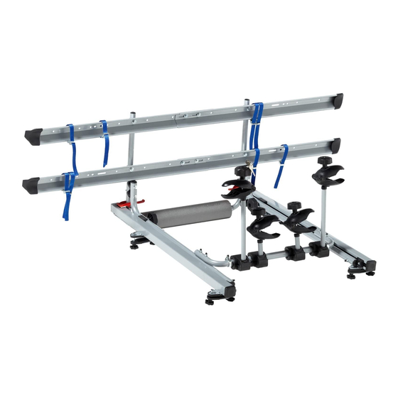
Porte-vélos avec aide au levage sur le toit

Publicité

Les langues disponibles
  • FR

Les langues disponibles

Liens rapides

Fahrradträger »Dachlift«
D
- für den sicheren liegenden Transport von zwei Fahrrädern -
Originalbetriebsanleitung
Inhalt
1. Sicherheitshinweise ....................................................................................... 2
2. Bestimmungsgemäßer Gebrauch ................................................................ 3
3. Werkzeug für den Zusammenbau ................................................................ 3
4. Teileliste Dachlift-Fahrradträger .................................................................. 4
5. Allgemeine Vorab-Informationen ................................................................. 7
6. Zusammenbauen ........................................................................................... 9
7. Service, Hersteller ........................................................................................ 20
Bicycle rack »Roof lift« .........................................................
- for safe transport of two bicycles in horizontal position -
- pour le transport sûr et couché de deux bicyclettes -
Portabici »Tetto auto« ...........................................................
- per il trasporto sicuro di 2 biciclette in posizione orizzontale -
- do bezpiecznego przewożenia maks. dwóch rowerów (w pozycji leżącej) -
18092_Betriebsanleitung_D_GB_F_IT_PL.indd 1
Art.-Nr.: 18092
Stand
02/2015
21
41
61
81
13.02.15 11:25

Publicité

loading

Sommaire des Matières pour FISCHER 18092

  • Page 1: Table Des Matières

    Fahrradträger »Dachlift« – für den sicheren liegenden Transport von zwei Fahrrädern – Originalbetriebsanleitung Art.-Nr.: 18092 Stand 02/2015 Inhalt 1. Sicherheitshinweise ..................2 2. Bestimmungsgemäßer Gebrauch ..............3 3. Werkzeug für den Zusammenbau ..............3 4. Teileliste Dachlift-Fahrradträger ..............4 5. Allgemeine Vorab-Informationen ..............7 6.
  • Page 2: Sicherheitshinweise

    Sehr geehrte Kunden, Vielen Dank, dass Sie sich für den FISCHeR Dachlift-Fahrradträger entschieden haben. Mit diesem Dachlift-Fahrradträger können Sie einfach und sicher zwei Fahrräder liegend mit Ihrem PKW transportieren. Dieser Dachlift-Fahrradträger wird als Bausatz geliefert. Sie müssen diesen Dachlift-Fahrradträger vor der ersten Verwendung sorgfältig anhand dieser Betriebsanleitung montieren.
  • Page 3: Bestimmungsgemäßer Gebrauch

    2. Bestimmungsgemäßer Gebrauch Der Dachlift-Fahrradträger dient zum Transport von zwei Fahrrädern auf dem Dach eines PKW. Der Dachlift-Fahrradträger muss entsprechend dieser Betriebsanleitung zusammengebaut werden. Im Fahrbetrieb müssen die entsprechenden gesetzlichen Bestimmungen (erlaubte Höchstgeschwindigkeit, höchst zulässiges Gesamtgewicht, etc.) eingehalten werden. 3. Werkzeug für den Zusammenbau Für den Zusammenbau benötigen Sie folgendes Werkzeug: 2 x Ø...
  • Page 4: Teileliste Dachlift-Fahrradträger

    4. Teileliste Dachlift-Fahrradträger Achtung: Wenn Sie mit diesen Einzelteilen arbeiten, achten Sie darauf, dass keine Kleinkinder in der Nähe sind. Der Dach-Fahrradträger enthält Kleinteile, die verschluckt werden können! Basiseinheit 1 + Fahrrad-Tragebügel 2 = Trageeinheit Teile Nr. Abbildung Bezeichnung Funktion / Verwendung Anzahl Basiseinheit Fahrrad-Haltearm...
  • Page 5 Teile Nr. Abbildung Bezeichnung Funktion / Verwendung Anzahl Die Stützrolle (3a) Führungsschiene Führung Trageeinheit / liegt rechts links Montage auf Grundträger Führung der aus- gezogenen Trageeinheit Stützrolle (vormontiert an Führungsschiene) Grundplatte vorne Auflage auf Grund- träger (vormontiert an Grundplatte hinten Führungsschiene) Teile Nr.
  • Page 6 Teile Nr. Abbildung Stückbeschreibung Funktion / Verwendung Anzahl Montage Führungsschiene Schlossschraube auf Grundträger mit Barren- M6 × 50 mm höhe bis 35 mm Montage Fahrrad-Tragebügel an Basiseinheit (4×) Schlossschraube Montage Führungsschiene M6 x 70 mm auf Grundträge mit Barren- höhe größer als 35 mm (8×) Schraubverbindungen Hutmutter M6 (außer bei Führungsschiene)
  • Page 7: Allgemeine Vorab-Informationen

    Die Trageeinheit kann in den Führungsschienen (3+4) nach vorne und nach hinten verschoben werden. Grundträger 5. Allgemeine Vorab-Informationen Schritt 1 Der Grundträger – Voraussetzung für die einwandfreie Funktion des Dachlift-Fahrradträgers Zunächst muss der Grundträger auf das Hinweis: Benutzen Sie ein Metermaß um die Fahrzeugdach montiert werden.
  • Page 8 Schritt 2 Vorbereitung des Trägers für die Montage, Trennung der Basis einheit (1) von den Führungsschienen (3+4) Bei Lieferung ist die Basiseinheit (1) zum Schutz der Führungsrollen (1c+1d) in die Führungs- schienen eingeschoben. Vor der Montage auf das Fahrzeug müssen Basiseinheit und Führungs- schienen getrennt werden.
  • Page 9: Zusammenbauen

    6. Zusammenbauen Schritt 3 Schritt 4 nun sind Basiseinheit und Führungs- Vormontage des Fahrrad-Trage- schienen voneinander getrennt. bügels (2) an die Basiseinheit (1) Vor Ihnen liegen die Teile: Für diesen Aufbauschritt benötigen Sie folgende Bauteile: Teile Nr. Abbildung Anzahl Teile Nr. Abbildung Anzahl Basiseinheit (1) Basiseinheit (1)
  • Page 10 1. Vor der Montage Schellen (2c) am Fahrrad- UnBeDInGT BeACHTen! Tragebügel lösen (nicht vollständig abdre- Rechte Sicherungsklammer – hen). Zur Anpassung der Breite des Fahrrad- rechts Linke Sicherungsklammer Tragebügels (2) an die Breite der Basisein- – links heit (1) die Rundrohre links und rechts aus dem Überwurfrohr ziehen bzw.
  • Page 11 Schritt 5 Schritt 6 Vor Ihnen liegt die Trageeinheit Montage der Führungsschienen (3+4) auf den Grundträger Für diesen Aufbauschritt benötigen Sie folgende Bauteile: Teile Nr. Abbildung Anzahl Führungsschiene links Führungsschiene rechts Unterlegscheibe, 6,5 mm, groß Schlossschraube M6 × 50 mm Befestigungs- platte Schutzprofil für...
  • Page 12 1. Schutzprofile (15) auf Grundplatte der 3. Schlossschraube (11) – bei Grundträgern mit Führungs schiene (3b+c/4b+c) und Barrenhöhe größer als 35 mm Schloss- Befestigungsplatte (14) aufdrücken. schrauben (12) verwenden – von oben in Bohrung der Grund platten (3b+c/4b+c) stecken, von unten Befes ti gungs platte (14) mit Gummi profil nach oben und Unter- legscheibe (8) aufstecken.
  • Page 13 Schritt 7 Breitenanpassung der Trageeinheit an Breite der Führungsschienen. Die Führungsschienen sind auf den 3. Trageeinheit vorsichtig mit Schaumstoff- Grundträger montiert. Profil (2b) an die Fahrzeugseite anlehnen und überprüfen, dass das Überwurf-Rohr 1. Schellenschrauben (1e+2c) an Trageeinheit mittig zwischen linker und rechter Seite positi- lösen (nicht vollständig abschrauben).
  • Page 14 Schritt 8 Zusammenstecken der Profilschienen (5) Für diesen Aufbauschritt benötigen Sie 1. Jeweils 2 Profilschienen (5) in der Mitte folgende Bauteile: zusammen legen. 2. Schraube (9) zuerst durch Unterleg scheibe Teile Nr. Abbildung Anzahl (8), dann an der Innenseite der Profil schiene durch die Lochung stecken.
  • Page 15 Schritt 9 Montage der Profilschiene (5) auf Trageeinheit Für diesen Aufbauschritt benötigen Sie folgende Bauteile: Teile Nr. Abbildung Anzahl Fahrrad-Profilschiene 750 mm Unterlegscheibe, 6,5 mm, klein Unterlegscheibe, 6,5 mm, groß Schraube M6 × 35 mm Hutmutter M6 Die Trageeinheit ist in der Breite angepaßt und in die Führungs schienen (3+4) eingehängt.
  • Page 16 Schritt 10 Hochliften der Trageeinheit auf das Fahrzeugdach Für diesen Aufbauschritt benötigen Sie folgende Bauteile: Teile Nr. Abbildung Anzahl Inbus-Schlüssel, 5 mm Die Profilschienen sind montiert. Die komplette 3. Trageeinheit vorne leicht anheben und Trageeinheit kann nun auf das Fahrzeugdach vordere Führungsrollen in Öffnung der geliftet werden.
  • Page 17 Inbusschrauben (5 mm) an den Anschlag- nur nach erstmontage: puffern lösen (nicht vollständig abschrauben). Die An schlagpuffer können nun verschoben werden. Richtige einstellung: Rundrohr der Trageeinheit Anschlag- Inbus- puffer schlüssel 5 mm 6. In Schritt 6.3 wurden die hinteren Befestigungsplatten (14) nur locker ange- Die Rundrohre der Trage einheit müssen bün- schraubt (für Ausrichtung der Führungs- dig an den Anschlag puffern anschlagen.
  • Page 18 Schritt 11 Absenken der Trageeinheit vom Fahrzeugdach an die Fahrzeugseite 1. Handrad (1f) links und rechts lösen (nicht 3. Trageeinheit weiter nach vorne ziehen, bis vollständig abdrehen!). Trageeinheit links und hintere Führungsrollen (1d) in der Führungs- rechts neben Schaumstoff-Profil (2b) greifen schiene anschlagen und langsam absenken, und Sicherungsklammern (2a) mit dem bis Schaumstoff-Profil (2b) an Fahrzeugseite...
  • Page 19 Schritt 12 Beladen der Fahrräder 1. Beim Beladen von 2 Rädern: Vor dem 2. Trageeinheit, wie in Schritt 11. beschrieben, Be laden des inneren Fahr rades den Lenker an die Fahrzeugseite absenken, Handrad drehen. Beladung mit Lenker nach rechts, am Fahrzeughaltearm lösen (nicht voll- Lenker des Fahr rades nach rechts drehen.
  • Page 20: Service, Hersteller

    Schritt 13 Abnehmen und Aufbewahren der beladenen Trageeinheit Für diesen Aufbauschritt benötigen Sie folgende Bauteile: Teile Nr. Abbildung Anzahl Haken Mit beiliegenden Schraubhaken 6 mm und Dübeln 6 mm kann die beladene Trageeinheit an geeigneter Stelle (Keller- oder Garagen- wand) platz sparend aufgehängt werden. Die Trageeinheit wie in Schritt 11.
  • Page 21: Gb Bicycle Rack »Roof Lift

    – für den sicheren liegenden Transport von zwei Fahrrädern – Bicycle rack »Roof lift« ............– for safe transport of two bicycles in horizontal position – Original instructions Art. no.: 18092 Version 02/2015 Table of contents 1. Safety instructions ..................22 2.
  • Page 22: Safety Instructions

    Dear customer, Thank you for choosing the FISCHeR Roof Lift Bike Rack. With this roof lift bike rack, you can easily and safely transport two horizontally positioned bicycles with your vehicle. The roof lift bike rack is delivered as an assembly set.
  • Page 23: Intended Use

    2. Intended use The roof lift bike rack is used to transport two bicycles on a vehicle roof. The roof lift bike rack must be assembled according to these operating instructions. Observe all applicable regulations (max. speed limit, max. permissible total weight, etc.) when driving. 3.
  • Page 24: Parts List For Roof Lift Bike Rack

    4. Parts list for roof lift bike rack Caution: Make sure no children are in the vicinity when working with these individual parts. The bike rack contains small parts that pose a choking hazard! Base unit 1 + bike carrying bracket 2 = carrying unit Parts No.
  • Page 25 Parts No. Image Label Function / Use Quantity The support roller (3a) is on Base unit guide / Left guide rail the right Assembly on base support Guide for extended Support roller carrying unit (pre- assembled on guide rail) Front base plate Rest on base support (preassembled on guide Back base plate...
  • Page 26 Parts No. Image Label Function / Use Quantity For assembly of guide rail Carriage bolt on base support with bar M6 x 50 mm height up to 35 mm For assembly of bike carrying bracket on base unit (4x) Carriage bolt For assembly of guide rail on M6 x 70 mm base support with bar height...
  • Page 27: General Preliminary Information

    The carrying unit can be moved forward and backward in the guide rails (3+4). base support 5. General preliminary information Step 1 base support – Prerequisite for proper functioning of the roof lift bike rack note: Use a tape measure to check the The base support must first be mounted to the vehicle roof.
  • Page 28 Step 2 Preparing the rack for assembly, remove the base unit (1) from the guide rails (3+4) On delivery, the base unit (1) is inserted into the guide rollers to protect the guide rollers (1c+1d). Before being mounted to the vehicle, the base unit and guide rails must be separated.
  • Page 29: Assembly

    6. Assembly Step 3 Step 4 now the base unit and guide rails are Preassembling the bike carrying separated. bracket (2) on the base unit (1) Parts in front of you: The following parts are required for this assembly step: Parts No.
  • Page 30 1. Before assembly, loosen the clamps (2c) on FOLLOW THIS STeP! the bike carrying bracket (do not screw off Right safety clamp - right Left safe- completely). To adjust the width of the bike ty clamp - left carrying bracket (2) to the width of the base unit (1) pull out/push in the round tubes on the left and right of the retaining tube.
  • Page 31 Step 5 Step 6 The carrying unit is in front of you Assembling the guide rails (3+4) to the base support The following parts are required for this assembly step: Parts No. Image Quantity Left guide rail Right guide rail Washer, 6.5 mm, large Carriage bolt, M6 x 50 mm...
  • Page 32 1. Push the protective profile (15) onto the base 3. Insert carriage bolt (11) - for use with base plate of the guide rails (3b+c/4b+c) supports with a bar height greater than 35 and mounting plate (14). mm, use carriage bolt (12) - from above into the hole on the base plates (3b+c/4b+c), attach mounting plate (14) from below with the rubber profile facing upward and washer...
  • Page 33 Step 7 Adjusting the width of the carrying unit to the width of the guide rails. The guide rails are mounted to the base 3. Carefully lean the carrying unit with foam support. profile (2b) on the side of the vehicle and verify that the retaining tube is directly in 1.
  • Page 34 Step 8 Connecting the profile guides (5) The following parts are required for this 1. Place 2 profile guides (5) together in the assembly step: middle. 2. Insert screw (9) first through the washer (8) Parts No. Image Quantity then through the hole on the inside of the profile guide.
  • Page 35 Step 9 Assembling the profile guides (5) on the carrying unit The following parts are required for this assembly step: Parts No. Image Quantity Bike profile guide 750 mm Washer, 6.5 mm, small Washer, 6.5 mm, large Screw M6 × 35 mm Cap nut M6 The width of the carrying unit is adjusted properly and the carrying unit is inserted...
  • Page 36 Step 10 Lifting the carrying unit onto the vehicle roof The following parts are required for this assembly step. Parts No. Image Quantity Hex key, 5 mm The profile guides are mounted. The entire 3. Slightly lift the carrying unit at the front and carrying unit can now be lifted onto the roof of lower the front guide rollers into the opening the vehicle.
  • Page 37 Loosen the hex screws (5 mm) on the bump Only after first assembly: stops (do not screw off completely). The bump stops can now be adjusted. Correct setting: Round tube on carrying unit Hex key, Bump stop 5 mm 6. In Step 6.3, the back mounting plates (14) were screwed on loosely (to adjust the guide rails).
  • Page 38 Step 11 Lower the carrying unit from the vehicle roof onto the vehicle side 1. Loosen the hand wheel (1f) left and right (do 3. Pull the carrying unit further forward until not screw off completely!). Hold the carrying the front guide rollers (1d) stop in the guide unit on the left and right near the foam rail and lower slowly until the foam profile profile (2b) and push the safety clamps (2a)
  • Page 39 Step 12 Loading bikes 1. When loading 2 bikes: Before loading the 2. As described in Step 10, lower the carrying inner bike, turn the handlebars. To load unit onto the side of the vehicle, loosen the with the handlebars on the right, turn the hand wheel on the vehicle bracket arm bike handlebars to the right.
  • Page 40: Service, Manufacturer

    Step 13 Remove and store the loaded carrying unit The following parts are required for this assembly step. Parts No. Image Quatity Hook Using the included screw hook 6 mm and wall anchors 6 mm, the loaded carrying unit can be suspended in a suitable location (basement or garage wall) with minimum space requirements.
  • Page 41: F Porte-Vélos Avec Aide Au »Levage Sur Le Toit

    – for safe transport of two bicycles in horizontal position – Porte-vélos avec aide au »levage sur le toit« ..... – pour le transport sûr et couché de deux bicyclettes – Mode d’emploi original Art. no° 18092 Version 02/2015 Table des matières 1.
  • Page 42: Consignes De Sécurité

    Cher client, chère cliente, Merci beaucoup d’avoir choisi un porte-vélos FISCHeR avec un système de levage sur le toit. Avec ce porte-vélos et son système de levage sur le toit, vous pouvez transporter facilement et en toute sécurité deux bicyclettes couchés sur votre voiture. Ce porte-vélos avec levage sur le toit est livré...
  • Page 43: Utilisation Conforme Aux Prescriptions

    2. Utilisation conforme aux prescriptions Le porte-vélos avec système de levage sur le toit sert au transport de deux bicyclettes sur le toit d‘une voiture. Le porte-vélos avec levage sur le toit doit être assemblé conformément à ce mode d’emploi. Pendant la conduite du véhicule, toutes les règlementations régies par la loi (vitesse maximale autorisée, poids total maximal admis, etc.) doivent être respectées.
  • Page 44: Liste Des Pièces Du Porte-Vélos Avec Levage Sur Le Toit

    4. Liste des pièces du porte-vélos avec levage sur le toit Attention : lorsque vous travaillez avec toutes les pièces, veillez à ce qu‘aucun enfant en bas âge ne se trouve à proximité. Le porte-vélos avec levage sur le toit contient des petites pièces qui peuvent être avalées ! Élément de base 1 + étrier de transport pour bicyclette 2 = élément de transport Pièce n°...
  • Page 45 Pièce n° Illustration Désignation Fonction/utilisation Quantité Guidage de l’élément de Roulette d‘appui (3a) se Rail de guidage transport/montage sur les trouvant à droite gauche barres de toit Guidage de l’élément de transport enlevé Roulette d‘appui (préassemblé sur le rail de guidage) Socle avant Revêtement sur les barres de toit (préassemblées sur...
  • Page 46 Pièce n° Illustration Désignation Fonction/utilisation Quantité Montage des rails de guidage sur Vis à tête bombée les barres de toit avec hauteur des M6 x 50 mm barres jusqu’à 35 mm Montage de l’étrier de transport pour bicyclette sur l’élément de Vis à...
  • Page 47: Informations Générales Préalables

    L‘élément de transport peut être décalé vers l’avant et vers l‘arrière dans les rails de guidage (3+4). Barres de toit 5. Informations générales préalables étape ère Les barres de toit – condition pour le fonctionnement parfait du porte-vélos avec levage sur le toit D‘abord, les barres de toit doivent être Remarque : utilisez un mètre afin de contrôler installées sur le toit du véhicule.
  • Page 48 étape Préparation du porte-vélos pour le montage – Séparation de l‘élément de base (1) des rails de guidage (3+4) À la livraison, l’élément de base (1) est inséré dans les rails de guidage afin de protéger les galets de guidage (1c+1d). Avant le montage sur le véhicule, l’élément de base et les rails de guidage doivent être séparés.
  • Page 49: Assemblage

    6. Assemblage étape étape Maintenant, l’élément de base et les Pré-assemblage de l’étrier de rails de guidage sont séparés l‘un de transport pour bicyclette (2) sur l‘autre l‘élément de base (1) Ces pièces se trouvent devant vous : Pour cette étape d’assemblage, vous avez besoin des pièces suivantes : Pièce n°...
  • Page 50 1. Avant le montage, démontez les brides (2c) À ReSPeCTeR ABSOLUMenT ! de l’étrier de transport pour bicyclette (ne Clip de sécurité droit – à droite pas démonter complètement). Pour adapter Clip de sécurité gauche – à gauche la largeur de l’étrier de transport pour bicyclette (2) à...
  • Page 51 étape étape L’élément de transport se trouve Montage des rails de guidage (3+4) devant vous sur les barres de toit Pour cette étape d’assemblage, vous avez besoin des pièces suivantes : Pièce n° Illustration Quantité Rail de guidage gauche Rail de guidage droit Rondelle plate, 6,5 mm, grande Vis à...
  • Page 52 1. Ouvrez le profilé de protection (15) sur le 3. Vis à tête bombée (11) – pour les barres de socle du rail de guidage (3b+c/4b+c) et la toit avec une hauteur de barres plus grande plaque de fixation (14). que 35 mm, utilisez les vis à...
  • Page 53 étape Réglage de la largeur de l‘élément de transport à la largeur des rails de guidage Les rails de guidage sont installés sur la base 3. Appuyez avec précaution l’élément de des barres de toit. transport avec le profilé et son rembourrage en mousse (2b) sur le côté...
  • Page 54 étape Assemblage des rails profilés (5) Pour cette étape d’assemblage, vous avez 1. Installez ensemble respectivement 2 rails besoin des pièces suivantes : profilés (5) au milieu. 2. Insérez d’abord la vis (9) au travers de la Pièce n° Illustration Quantité...
  • Page 55 étape Montage du rail profilé (5) sur l’élément de transport Pour cette étape d’assemblage, vous avez besoin des pièces suivantes : Pièce n° Illustration Quantité Rail profilé pour bicyclette, 750 mm Rondelle plate, 6,5 mm, petite Rondelle plate, 6,5 mm, grande Vis M6 ×...
  • Page 56 étape Levage de l’élément de transport sur le toit du véhicule Pour cette étape d’assemblage, vous avez besoin des pièces suivantes : Pièce n° Illustration Quantité Clé hexagonale, 5 mm Les rails profilés sont installés. L’élément de 3. Soulevez légèrement l’élément de transport transport dans son ensemble peut maintenant à...
  • Page 57 Desserrez les vis à tête à six pans (5 mm) Seulement après le premier montage : sur l‘appui de butée (ne pas dévisser complètement). Les appuis de butée peuvent maintenant être décalés. Tube rond de Réglage correct : l‘élément de transport Clé...
  • Page 58 étape Abaisser l‘élément de transport du toit du véhicule sur le côté du véhicule 1. Desserrez la molette (1f) à gauche et à droite 3. Continuez à tirer vers l’avant l’élément de (ne pas desserrer complètement) ! Saisissez transport, jusqu‘à ce que les galets de l’élément de transport à...
  • Page 59 étape Chargement des bicyclettes 1. Lors du chargement de 2 vélos : tournez 2. Abaissez l’élément de transport, comme le guidon avant de charger la bicyclette décrit dans la 11e étape, sur le côté du interne. Chargement avec guidon vers la véhicule ;...
  • Page 60: Service, Fabricant

    étape enlever et conserver l‘élément de transport chargé Pour cette étape d’assemblage, vous avez besoin des pièces suivantes : Pièce n° Illustration Quantité Crochet Avec les crochets à pas de vis de 6 mm et de chevilles de 6 mm, l’élément de transport chargé...
  • Page 61: It Portabici »Tetto Auto

    – pour le transport sûr et couché de deux bicyclettes – Portabici »Tetto auto« ............– per il trasporto sicuro di 2 biciclette in posizione orizzontale – Manuale d’uso originale Articolo N°: 18092 Versione 02/2015 Contenuto 1. Precauzioni di sicurezza ................62 2.
  • Page 62: Precauzioni Di Sicurezza

    Gentili clienti, Grazie per aver scelto il portabici per tetto auto FISCHeR. Con questo portabici per tetto auto potrete trasportare in modo facile e sicuro due biciclette in posizione orizzontale con la vostra auto. Questo portabici per tetto auto viene fornito in kit di montaggio.
  • Page 63: Uso Previsto

    2. Uso Previsto Il portabici per tetto auto serve a trasportare due biciclette sul tetto di un’automobile. Il portabici per tetto auto deve essere assemblato secondo questo manuale. Durante la guida vanno osservate le pertinenti disposizioni di legge (velocità massima consentita, peso complessivo massimo ammesso, etc.).
  • Page 64: Elenco Parti Del Portabici Per Tetto Auto

    4. elenco parti del portabici per tetto auto Attenzione: Se si sta lavorando con queste parti, accertarsi che non vi siano bambini piccoli nelle vicinanze. Il portabici per tetto auto contiene piccole parti che possono essere ingerite! Unità di base 1 + Staffa di supporto della bicicletta 2 = Unità di supporto Num.
  • Page 65 Num. Figura Denominazione Funzione / Uso Quantità parti Guida dell’unità di supporto Il rullo di supporto (3a) è sulla Rotaia di guida / Montaggio sul supporto destra sinistra di base Guida dell’unità di supporto estratta Rullo di supporto (premontata sulle rotaie di guida) Piastra di base Strato sul supporto di...
  • Page 66 Num. Figura Denominazione Funzione / Uso/utilisation Quantità parti Montaggio della rotaia di guida Vite a testa tonda sul supporto di base con altezza M6 x 50 mm barre fino a 35 mm Montaggio della staffa di supporto della bicicletta sull’ Vite a testa tonda unità...
  • Page 67: Informazioni Generali Preliminari

    L’unità di supporto può essere spostata nelle rotaie di guida (3 + 4) in avanti e indietro. Supporto di base 5. Informazioni generali preliminari Punto 1 Il supporto di base – un requisito essenziale per il corretto funzionamento del portabici per tetto auto Innanzitutto, il supporto di base deve essere Si prega di notare: Utilizzare un metro a installato sul tetto del veicolo.
  • Page 68 Punto 2 Preparazione del supporto per il montaggio – Separazione dell’unità di base (1) dalle rotaie di guida (3 + 4) Alla consegna, l’unità di base (1) è inserita nelle rotaie di guida per proteggere i rulli di guida (1c+1d). Prima del montaggio sul veicolo, l’unità di base e le rotaie di guida devono essere separate.
  • Page 69: Montaggio

    6. Montaggio Punto 3 Punto 4 Ora l’unità di base e le rotaie di guida Premontaggio della staffa di sono separate supporto della bicicletta (2) sull’unità di base (1) Di fronte a voi vi sono le seguenti parti: Per questo passaggio sono necessari i seguenti componenti: Num.
  • Page 70 1. Prima del montaggio allentare le fascette PReSTARe ATTenZIOne! (2c) sulla staffa di supporto della bicicletta Clip di fissaggio destra - a destra (non girare completamente). Per adattare Clip di fissaggio sinistra - a sinistra la larghezza della staffa di supporto della bicicletta (2) a quella dell’unità...
  • Page 71 Punto 5 Punto 6 Di fronte a voi vi è l’unità di supporto Montaggio delle rotaie di guida (3+4) sul supporto di base Per questo passaggio sono necessari i seguenti componenti: Num. Figura Quantità parti Rotaia di guida sinistra Rotaia di guida destra Rondella, 6,5 mm, grande...
  • Page 72 1. Premere i profili di protezione (15) sulla 3. Inserire la vite a testa tonda (11) – per piastra di base della rotaia di guida supporti di base con altezza barre superiore (3b+c/4b+c) e la piastra di fissaggio (14). a 35 mm utilizzare viti a testa tonda (12) –...
  • Page 73 Punto 7 Adattamento della larghezza dell’unità di supporto a quella delle rotaie di guida Le rotaie di guida sono montate sul supporto 3. Appoggiare delicatamente l’unità di di base. supporto con il profilo in schiuma (2b) sul lato del veicolo e verificare che il tubo di 1.
  • Page 74 Punto 8 Unione delle guide profilate (5) Per questo passaggio sono necessari i 1. Unire 2 guide profilate (5) al centro. seguenti componenti: 2. Inserire la vite (9) dapprima attraverso Num. la rondella (8), poi all’interno della guida Figura Quantità parti profilata attraverso il foro.
  • Page 75 Punto 9 Montaggio della guida profilata (5) sull’unità di supporto Per questo passaggio sono necessari i seguenti componenti: Num. Figura Quantità parti Guida profilata bicicletta, 750 mm Rondella, 6,5 mm, piccola Rondella, 6,5 mm, grande Vite M6 × 35 mm Dado cieco M6 L’unità...
  • Page 76 Punto 10 Sollevamento dell’unità di supporto sul tetto del veicolo Per questo passaggio sono necessari i seguenti componenti: Num. Figura Quantità parti Chiave a brugola , 5 mm Le guide profilate sono installate. L’unità di 3. Sollevare leggermente l’unità di supporto supporto completa può...
  • Page 77 Allentare le viti a brugola (5 mm) sui tamponi Solo dopo il montaggio iniziale: d’arresto (non svitare completamente). I tamponi d’arresto ora possono essere spostati. Impostazione corretta: Tubo circolare dell’unità di supporto Chiave a brugola Tampone 5 mm d’arresto 6. Al punto 6.3, le piastre di fissaggio posteriori (14) sono state avvitate solo leggermente I tubi circolari dell’unità...
  • Page 78 Punto 11 Abbassamento dell’unità di supporto dal tetto al lato del veicolo 1. Allentare la manopola (1f) a sinistra e a destra 3. Tirare l’unità di supporto ulteriormente in (non girare completamente!). Afferrare l’unità avanti finché i rulli di guida posteriori (1d) non di supporto a destra e a sinistra del profilo si arrestino nella rotaia di guida e abbassare in schiuma (2b) e premere le clip di fissaggio...
  • Page 79 Punto 12 Caricamento delle biciclette 1. Prima di caricare la bicicletta interna 2. Abbassare l’unità di supporto sul lato del ruotare il manubrio. Per il caricamento con veicolo come descritto al punto 11, allentare manubrio a destra, ruotare il manubrio della la manopola sul braccio di supporto bici bicicletta verso destra.
  • Page 80: Assistenza, Produttore

    Punto 13 Rimozione e conservazione dell’unità di supporto caricata Per questo passaggio sono necessari i seguenti componenti: Num. Figura Quantità parti Gancio Con i ganci a vite da 6 mm e i tasselli da 6 mm in dotazione, l’unità di supporto caricata può essere appesa in un luogo adatto (parete della cantina o del garage) per risparmiare spazio.
  • Page 81: Pl Bagażnik Na Rowery »Dachowego Bagażnika

    Bagażnik na rowery »Dachowego bagażnika« ....– do bezpiecznego przewożenia maks. dwóch rowerów (w pozycji leżącej) – Tłumaczenie oryginalnej instrukcji obsługi nr art.: 18092 – 01/2015 Zawartość 1. Wskazówki dotyczące bezpieczeństwa użytkowania ......82 2. Użytkowanie zgodne z przeznaczeniem ........... 83 3.
  • Page 82: Wskazówki Dotyczące Bezpieczeństwa Użytkowania

    Drodzy Klienci, Dziękujemy za zakup dachowego bagażnika rowerowego firmy FISCHER. Dzięki temu bagażnikowi mogą Państwo w łatwy i bezpieczny sposób przewozić rowery samochodem. Jednocześnie wolno przewozić maksymalnie dwa rowery zamocowane w pozycji leżącej. Niniejszy dachowy bagażnik do przewożenia rowerów dostarczany jest jako zestaw przeznaczony do złożenia.
  • Page 83: Użytkowanie Zgodne Z Przeznaczeniem

    • Zapasowe kluczyki do zamykanego pokrętła należy przechowywać oddzielnie, w bezpiecznym miejscu. • Przestrzegać wskazówek dotyczących montażu. • Producent oraz dystrybutor wyrobu nie ponoszą odpowiedzialności za uszkodzenia pojazdu i/lub rowerów wynikłe z nieprzestrzegania wskazówek dotyczących montażu oraz instrukcji bezpieczeństwa. 2. Użytkowanie zgodne z przeznaczeniem Dachowy bagażnik rowerowy służy do przewożenia maksymalnie dwóch rowerów na dachu pojazdu samochodowego.
  • Page 84: Wykaz Części Dachowego Bagażnika Rowerowego

    4. Wykaz części dachowego bagażnika rowerowego Uwaga: Podczas pracy z tymi elementami należy dopilnować, aby w pobliżu nie znajdowały się dzieci. Dachowy bagażnik rowerowy zawiera małe części, które mogą zostać połknięte! Jednostka podstawowa 1 + Uchwyt rowerowy 2 = bagażnik Nr części Rysunek Opis...
  • Page 85 Nr części Rysunek Opis Funkcja/zastosowanie Liczba Prowadnik bagażnika/ Krążek podtrzymujący (3a) po Szyna prowadząca montaż na podstawie prawej stronie lewa nośnej Prowadnik rozłożonego Krążek bagażnika (wstępnie podtrzymujący zamontowany na szynie prowadzącej) Przednia płyta Podkładka na podsta- podstawy wie nośnej (uprzednio zamontowana na szynie Tylna płyta podstawy prowadzącej)
  • Page 86 Nr części Rysunek Opis Funkcja/zastosowanie Liczba Mocowanie szyny prowadzącej Śruba podsadzana na podstawie nośnej z belkami o M6 x 50 mm wysokości do 35 mm Mocowanie uchwytu rowerowego na jednostce bazowej (4x), Śruba podsadzana Mocowanie szyny prowadzącej M6 x 70 mm na podstawie nośnej z belkami o wysokości większej niż...
  • Page 87: Informacje Ogólne

    Bagażnik można przesuwać do przodu i do tyłu po szynach prowadzących (3+4). Podstawa nośna 5. Informacje ogólne Krok 1 Podstawa nośna — element niezbędny, aby zagwarantować prawidłowe funkcjonowanie dachowego bagażnika rowerowego W pierwszej kolejności należy zamontować Wskazówka: aby sprawdzić odstępy między podstawę...
  • Page 88 Krok 2 Przygotowanie bagażnika do montażu – zdejmowanie jednostki bazowej (1) z szyn prowadzących (3+4) W celu zabezpieczenia rolek prowadzących (1c + 1d) jednostka bazowa (1) została nasunięta na szyny prowadzące na czas dostawy. Przed montażem na pojeździe jednostkę bazową należy zdjąć...
  • Page 89: Montaż

    6. Montaż Krok 3 Krok 4 Teraz jednostka bazowa oraz szyny Wstępne mocowanie bagażnika prowadzące są od siebie oddzielone rowerowego (2) do jednostki bazowej (1) Części powinny wyglądać w następujący Na tym etapie montażu potrzebne będą sposób: następujące części: Nr części Rysunek Liczba Nr części Rysunek Liczba...
  • Page 90 1. Przed montażem należy poluzować zacisk BEZWZGLĘDNIE (2c) na uchwycie rowerowym (nie odkręcać PRZESTRZEGAĆ! całkowicie). Aby dopasować szerokość Prawy zacisk zabezpieczający uchwytu rowerowego (2) do szerokości – po prawej; Lewy zacisk jednostki bazowej (1), rury zamocowane po zabezpieczający – po lewej lewej i prawej stronie należy zdjąć...
  • Page 91 Krok 5 Krok 6 Bagażnik na tym etapie wygląda w Mocowanie szyn prowadzących (3+4) następujący sposób na podstawie nośnej Na tym etapie montażu potrzebne będą następujące części: Nr części Rysunek Liczba Szyna prowadząca lewa Szyna prowadząca prawa Podkładka, 6,5 mm, duża Śruba podsadzana, M6 x 50 mm...
  • Page 92 1. Profil ochronny (15) należy docisnąć do płyty 3. Śruba podsadzana (11) – niezbędna w bazowej szyny prowadzącej (3b+c/4b+c) przypadku mocowania do podstawy nośnej oraz do płyty mocującej (14). z belkami o wysokości powyżej 35 mm Sposób użycia śrub podsadzanych (12) –...
  • Page 93 Krok 7 Dopasowywanie szerokości bagażnika do szerokości szyn prowadzących. Szyny prowadzące należy zamontować na 3. Bagażnik należy ostrożnie oprzeć na podstawie nośnej. profilu z pianki z tworzywa sztucznego (2b) po stronie pojazdu i upewnić się, że rura 1. Poluzować śruby zaciskowe (1e+2c) łącząca znajduje się...
  • Page 94 Krok 8 Montaż szyn profilowanych (5) Na tym etapie montażu potrzebne będą 1. Nałożyć na siebie 2 profilowane szyny (5). następujące części: 2. Śrubę (9) włożyć w podkładkę (8), a następnie wsunąć w otwór znajdujący się po Nr części Rysunek Liczba wewnętrznej stronie profilowanej szyny.
  • Page 95 Krok 9 Mocowanie profilowanej szyny (5) na bagażniku Na tym etapie montażu potrzebne będą następujące elementy: Num. Figura Quantità parti Profilowana szyna rowerowa, 750 mm Podkładka, 6,5 mm, mała Podkładka, 6,5 mm, duża Śruba M6 × 35 mm Nakrętka kołpakowa M6 Na tym etapie szerokość...
  • Page 96 Krok 10 Podnoszenie bagażnika na dach pojazdu Na tym etapie montażu potrzebne będą następujące elementy: Nr części Rysunek Liczba Klucz imbusowy, 5 mm Profilowane szyny są już zamontowane. W 3. Nieznacznie podnieść przednią część pełni złożony bagażnik można teraz podnieść bagażnika i wsunąć...
  • Page 97 Poluzować śruby imbusowe (5 mm) przy Wyłącznie podczas pierwszego montażu: odbojniku (nie należy odkręcać ich całkowicie). Odbojnik można teraz przesunąć. Prawidłowy montaż: Rura bagażnika Klucz imbusowy 5 mm Odbojnik 6. W kroku 6.3 tylne płyty montażowe (14) zostały jedynie lekko przykręcone (aby Rura bagażnika musi dokładnie zaskoczyć...
  • Page 98 Krok 11 Zdjąć bagażnik z dachu pojazdu, opuszczając go po stronie pasażera. 1. Poluzować pokrętła po lewej i prawej stronie 3. Przesuwać bagażnik do przodu, aż tylna (1f) (nie odkręcać całkowicie!). Chwycić rolka prowadząca (1d) zaskoczy w szynie bagażnik po obu stronach. Po bokach profilu prowadzącej.
  • Page 99 Krok 12 Ładowanie rowerów 1. W przypadku ładowania 2 rowerów: Przed 2. Zsunąć bagażnik w sposób opisany w Kroku załadowaniem roweru, który znajdować 11 (po stronie pasażera). Poluzować pokrętło się będzie na spodzie należy przekręcić przy ramieniu uchwytu rowerowego (nie jego kierownicę.
  • Page 100: Serwis, Producent

    Krok 13 Zdejmowanie i przechowywanie bagażnika z załadowanymi rowerami Na tym etapie montażu potrzebne będą następujące elementy: Nr części Rysunek Liczba Za pomocą dołączonych gwintowanych haków 6 mm i kołków rozporowych można powiesić bagażnik w odpowiednim miejscu (np. w piwnicy lub w garażu). Rozwiązanie to pozwala zaoszczędzić...