Publicité

Les langues disponibles

Les langues disponibles

Liens rapides

ISO - TECH IDM 91E
DIGITAL MULTIMETER
INSTRUCTION MANUAL
1

Publicité

Table des Matières
loading

Sommaire des Matières pour Iso-Tech IDM 91E

  • Page 1 ISO - TECH IDM 91E DIGITAL MULTIMETER INSTRUCTION MANUAL...
  • Page 3 # WARNING THESE SERVICING INSTRUCTIONS ARE FOR USE BY QUALIFIED PERSONNEL ONLY. TO AVOID ELEC- TRIC SHOCK, DO NOT PERFORM ANY SERVICING OTHER THAN THAT CONTAINED IN THE OPERATING INSTRUCTIONS UNLESS YOU ARE QUALIFIED TO DO SO. TO AVOID ELECTRIC SHOCK, DISCONNECT MEASURING TERMINALS BEFORE OPENING ENCLOSURE.
  • Page 4 INTRODUCTION 1-1 Unpacking and Inspection Upon removing your new Digital Multimeter from its packing, you should have the following items: 1. Digital Multimeter. 2. Test lead set (one black, one red). 3. Instruction Manual. 4. Protective holster. 1-2 Meter Safety Terms marked on Equipment ATTENTION —...
  • Page 5 Symbols in this Manual This symbol indicates where cautionary or other information is found in the manual. Battery 1-3 Front Panel Refer to Figure 1 and the following numbered steps to familiarize yourself with the meter's front panel controls and connectors.
  • Page 7 SPECIFICATIONS 2-1 General Specifications This instrument has been designed and tested in accordance with IEC Publication 1010 Pt 1, Class II, Safety Re- quirements for Electrical Equipment for Measurement, Control and Laboratory Use. This level of safety can only be guaranteed while the limits of section 2.2 are observed.
  • Page 8 2-2 Environmental Conditions: Maximum Altitude : 2000m Installation Category : IEC 1010 600V CAT II 300V CAT III. Pollution Degree : 2 Operating Temperature : 0°C to 50°C, 0 to 80% R.H. Storage Temperature : -20°C to 60°C, 0 to 80% R.H when battery removed from meter. Temperature Coefficient : 0.15 x (Specified accuracy) / °C, <18°C or >28°C.
  • Page 9 2-3 Electrical Specifications Accuracy is ± (% reading + number of digits) at 23°C ± 5°C, less than 75% R.H. Range Resolution Accuracy Over voltage 200mV 100 µV ±(0.5%reading + 1digit) 600V d.c. or 600 V a.c. rms 10mV 200V 100mV 600V è...
  • Page 10 (2) AC Volts Over voltage Range Resolution Accuracy 200mV 100 µV ±(1.25%reading + 4digit) 600V d.c. or 600 V a.c. rms 10mV 40Hz — 500Hz 200V 100mV 600V è Input Impedance : 10M , less than 100pF...
  • Page 11 (3) DC Current Range Resolution Accuracy Voltage Burden 200 µA 0.1 µA 1 µA 600mV max. ±(1.0%reading + 1digit) 20mA 10 µA 200mA 100 µA 900mV max. 10mA ±(2.0%reading + 3digit) Overload Protection : 1A/415V fast blow fuse for mA, µA input. 10A/415V fast blow fuse for 10A input.
  • Page 12 (4) AC Current Range Resolution Accuracy Voltage Burden 200 µA 0.1 µA 1 µA 600mV rms max. ±(1.5%reading + 3digit) 40Hz — 500Hz 20mA 10 µA 200mA 100 µA 900mV rms max. ±(2.5%reading + 3digit) 10mA 40Hz — 500Hz Overload Protection : 1A/415V fast blow for mA, µA input. 10A/415V fast blow for 10A input.
  • Page 13 (5) Resistance Max.Test Max.Open Range Resolution Accuracy è è ±(07.5%reading + 4digit) 2.5mA 3.2V è è 200 µA è è 40 µA è è ±(07.5%reading + 1digit) 4 µA 200K 0.5V è è 400nA è è ±(1.5%reading + 4digit) 40nA Overload Protection: 500V d.c/a.c max.
  • Page 14 (6) Diode Check Range Resolution Accuracy Max.Test Max.Open ±(1.5%reading + 5digit) 1.5mA 3.2V * Overload Protection: 500V d.c/a.c max. Instant Continuity Description: è Internal sounder operates when resistance is less than 50 (7) Auto Power Off: The meter will automatically shut itself off after approximately 30 minutes when the rotary switch is not changed. The meter can be turned back on by switching to another range.
  • Page 15 OPERATION 3-1 Preparation and Caution before Measurement 1. Allow at least 60 seconds after switching on before taking measurements. 2. Remove test leads from the circuit under test before changing the measurement range. 3. If the equipment is used near noise generating equipment, be aware that the display may become unstable or indicate large errors.
  • Page 16 TEST EQUIPMENT RISK ASSESSMENT (UK RECOMMENDATION) Users of this equipment and/or their employers are reminded that Health and Safety legislation require them to carry out valid risk assessments of all electrical work so as to identify potential sources of electrical danger and risk of electrical injury such as from inadvertent short circuits.
  • Page 17 3-3 Current Measurements 1. Set the rotary switch to the required position. 2. Connect black test lead to "COM" terminal. 3. Connect red test lead to "mA/µA" terminal for measurement up to 200mA. For measuring current between 200mA and 10A, connect test lead to "10A" terminal. 4.
  • Page 18 3-5 Diode Check 1. Set the rotary switch to the " " position. è 2. Connect the black test lead to the "COM" terminal and the red test lead to the "V " input terminal. 3. Connect the test lead to the diode. Normally the forward voltage drop of good silicon diode is shown between .500V and .900V.
  • Page 19 MAINTENANCE To keep the instrument clean, wipe the case with a damp cloth and detergent, do not use abrasives or solvents. Any adjustment, maintenance and repair of opened instrument with voltage present shall be avoided as far as pos- sible and, if inevitable, shall be carried out by a skilled person who is aware of the hazard involved. Whenever it is likely that the protection has been impaired, the instrument shall be made inoperative and be secured against any unintended operation.
  • Page 20: Battery Replacement

    BATTERY REPLACEMENT The meter is powered by a single 9V battery. Refer to Figure 2A and use the following procedure to replace the battery: 1. Disconnect the test leads and turn the meter off. Remove the test leads from the front terminals. 2.
  • Page 21: Fuse Replacement

    FUSE REPLACEMENT Refer to Figure 2B and use the following procedure to examine or replace the meter's fuse: 1. Perform steps 1 through 3 of the battery replacement procedure. 2. Lift the circuit board from the case top. Do not remove the screws from the circuit board. 3.
  • Page 27 ISO - TECH IDM 91E MULTIMETRE NUMERIQUE MANUEL D'INSTRUCTIONS...
  • Page 29 # AVERTISSEMENT CES INSTRUCTIONS D'ENTRETIEN SONT DESTINEES A DU PERSONNEL COMPETENT SEULEMENT. POUR EVITER DES CHOCS ELECTRIQUES, NE PAS EFFECTUER D'ENTRETIEN AUTRE QUE CELUI IN- DIQUE DANS LES INSTRUCTIONS D'UTILISATION, A MOINS D'ETRE QUALIFIE POUR LE FAIRE. POUR EVITER DES CHOCS ELECTRIQUES, DEBRANCHER LES BORNES DE MESURE AVANT D'OUVRIR LE BOITIER.
  • Page 30 INTRODUCTION 1-1 Déballage et inspection Voici les articles qui devraient accompagner le multimètre numérique lors de son déballage : 1. Multimètre numérique. 2. Jeu de fils d'essai (un noir et un rouge). 3. Manuel d'instructions. 4. Etui protecteur. 1-2 Sécurité du compteur Termes marqués sur l'équipement ATTENTION —...
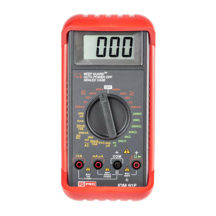
  • Page 31 Symboles utilisés dans ce manuel Ce symbole indique où se trouvent des avertissements ou autres renseignements dans le manuel. Pile 1-3 Panneau avant Consulter la figure 1 et les étapes numérotées suivantes pour se familiariser avec les commandes et les connec- teurs du panneau avant du multimètre.
  • Page 33 SPECIFICATIONS 2-1 Spécifications générales Cet instrument a été étudié et vérifié conformément à la publication 1010, partie 1, de l'IEC, Classe II, Exigences de sécurité pour l'équipement électrique de mesure, de contrôle et pour laboratoires. Ce niveau de sûreté ne peut être garanti que si on observe les limites de la Section 2.2.
  • Page 34 2-2 Conditions environnementales Altitude maximale : 2000 m Catégorie d'installation : IEC 1010 600 V CAT II, 300 V CAT III. Niveau de pollution : 2 Température d'utilisation : 0°C à 50°C, humidité relative de 0 à 80 %. Température de stockage : -20°C à 60°C, humidité relative de 0 à 80% quand la pile est enlevée du multimètre. Coefficient de température : 0,15 x (précision spécifiée) / °...
  • Page 35 2-3 Spécifications électriques La précision est ± (% de lecture + le nombre de chiffres) à 23°+ ± 5°C, humidité relative inférieure à 75 %. (1) Tension c.c. Plage Résolution Précision Protection contre 200mV 100 µV ±(Lecture de 0,5% + 1 chiffre) 600 V c.c.
  • Page 36 (2) Tension c.a Protection contre Plage Résolution Précision 200mV 100 µV ±(Lecture de 1,25% + 4 chiffres) 600 V c.c. ou 600 V c.a. rms 10mV 40Hz — 500Hz 200V 100mV 600V è Impédance d'entrée : 10M , inférieur à 100 pF.
  • Page 37 (3) Courant continu Plage Résolution Précision Charge de tension 200mV 100 µV 600mV maximum ±(Lecture de 1,0% + 1 chiffre) 10mV 200V 100mV 900mV maximum 600V ±(Lecture de 2,0% + 3 chiffres) Protection contre les surcharges : Fusible à fusion rapide de 1 A/415 V pour entrée en mA, µ. Fusible à...
  • Page 38 (4) Courant alternatif Plage Résolution Précision Charge de tension 200 µA 0.1 µA 1 µA 600V rms maximum ± (1,5 % de lecture + 3 chiffres) 40Hz — 500Hz 20mA 10 µA 200mA 100 µA 900V rms maximum ± (2,5 % de lecture + 3 chiffres) 10mA 40Hz —...
  • Page 39 (5) Résistance Plage Résolution Précision Essai maximal Circuit ouvert maximal è è ±(Lecture de 0,75% + 4 chiffres) 2.5mA 3,2V è è 200 µA è è 40 µA è è ±(Lecture de 0,75% + 1 chiffres) 4 µA 200K 0,5V è...
  • Page 40 (6) Vérification de la diode Plage Résolution Précision Essai maximal Circuit ouvert maximal ± (1,5 % de lecture + 5chiffres) 1.5mA 3.2V * Protection contre les surcharges: 500 V c.c./c.a. maximum Description de la continuité instantanée: è Le sondeur interne fonctionne quand la résistance est inférieure à 50 (7) Extinction automatique Le multimètre s'éteint automatiquement après environ 30 minutes, quand la position du commutateur rotatif n'a pas été...
  • Page 41: Fonctionnement

    FONCTIONNEMENT 3-1 Préparation et avertissement avant les mesures 1. Attendre au moins 60 secondes après avoir allumé l'appareil avant de prendre des mesures. 2. Enlever les fils d'essai du circuit en cours d'essai, avant de changer la plage de mesure. 3.
  • Page 42 AVERTISSEMENT POUR EVITER LES CHOCS ELECTRIQUES, LES DANGERS OU LES RISQUES POUR LE MULTIMETRE, NE PAS ESSAYER DE MESURER DES TENSIONS QUI POURRAIENT DEPASSER 600 V c.c. OU 600 V c.a. rms. NE PAS RACCORDER PLUS DE 600 V C.C. OU 600 V c.a. RMS ENTRE LA BORNE D'ENTREE COMMUNE ET LA MISE A LA TERRE.
  • Page 43 3-3 Mesures de courants 1. Régler le commutateur rotatif à la position voulue. 2. Raccorder le fil d'essai noir à la borne COM. 3. Raccorder le fil d'essai rouge à la borne mA/µA pour des mesures jusqu'à 200 mA. Pour mesurer des courants entre 200 mA et 10 A, raccorder le fil d'essai à la borne 10 A. 4.
  • Page 44 3-5 Vérification de la diode 1. Régler le commutateur rotatif à . è 2. Raccorder le fil d'essai noir à la borne COM, et le fil d'essai rouge à la borne V 3. Raccorder le fil d'essai à la diode. Normalement, la chute de tension avant d'une bonne diode au silicium est entre 0,5 V et 0,9 V.
  • Page 45 MAINTENANCE Afin de maintenir l'instrument propre, essuyer le boîtier avec un chiffon humide et un détergent; ne pas utiliser d'abrasifs ni de solvants. Il faut éviter autant que possible d'effectuer tous réglages, entretiens et réparations sur un instrument ouvert et sous tension et, si c'est inévitable, ces travaux doivent être effectués par du personnel compétent connaissant les risques encourus.
  • Page 46: Remplacement Des Piles

    REMPLACEMENT DES PILES Le thermomètre est muni d'une pile de 9 V. Consulter la figure 2A et suivre la procédure suivante pour remplacer les piles : 1. Débrancher les fils d'essai et éteindre le compteur. Enlever les fils d'essai des bornes avant. 2.
  • Page 47: Remplacement Du Fusible

    REMPLACEMENT DU FUSIBLE Consulter la figure 2B et utiliser la procédure suivante pour examiner ou pour remplacer le fusible du multimètre : 1. Effectuer les étapes 1 à 3 de la procédure de remplacement de pile. 2. Relever la carte de circuits du haut du boîtier. Ne pas enlever les vis de la carte de circuits. 3.
  • Page 52 ISO - TECH IDM 91E DIGITALES MULTIMETER BEDIENERHANDBUCH...
  • Page 54 ACHTUNG DIESE WARTUNGSANWEISUNGEN SIND NUR FÜR FACHPERSONAL BESTIMMT. ZUR VERMEIDUNG VON STROMSCHLAG SOLLTEN SIE WARTUNGSARBEITEN, DIE NICHT IN DIESEM HANDBUCH BESCHRIEBEN SIND, NUR DURCHFÜHREN, WENN SIE ÜBER EINE ENTSPRECHENDE FACHAUSBILDUNG VERFÜGEN. ZUR VERMEIDUNG VON STROMSCHLAG GERÄT VON DEN MESSKLEMMEN TRENNEN, BEVOR SIE DIE ABDECKUNG ÖFFNEN.
  • Page 55 EINLEITUNG 1-1 Auspacken Nachdem Sie das neue digitale Multimeter ausgepackt haben, sollten Sie den Lieferumfang anhand der folgenden Aufstellung auf Vollständigkeit prüfen. 1. Digitales Multimeter. 2. Prüfkabelset (ein schwarzes, ein rotes Kabel). 3. Bedienungsanleitung. 4. Schutzholster. 1-2 Sicherheit des Meßgeräts Bitte Hinweise auf dem Gerät beachten.
  • Page 56 In diesem Handbuch verwendete Symbole Mit diesem Symbol sind alle wichtigen Hinweise in diesem Handbuch gekennzeichnet. Batterie 1-3 Vorderansicht Die Angaben in Abbildung 1 und die nachfolgende, schrittweise Beschreibung helfen Ihnen, sich mit den Betätigungselementen und den Anschlüssen des Geräts vertraut zu machen. 1.
  • Page 58: Technische Daten

    TECHNISCHE DATEN 2-1 Allgemeine technische Daten Dieses Meßgerät wurde gemäß IEC Normen 1010 Pt 1, Klasse II, Sicherheitsbestimmungen für elektrische Meß-, Kontroll- und Laborgeräte, konstruiert. Dieser Sicherheitsstandard kann nur garantiert werden, wenn die in Punkt 2.2 genannten Grenzwerte beachtet werden. Anzeige : 3 1/2-stellige Anzeige (LCD) (max.
  • Page 59 2-2 Umgebungsbedingungen: Höhe über dem Meeresspiegel : max. 2000m Installationskategorie : IEC 1010, 600V, Kat II, 300V, Kat III. Verschmutzungsgrad : 2 Betriebstemperatur : 0°C bis 50°C, 0 bis 80% relative Luftfeuchtigkeit. Lagertemperatur : -20°C bis 60°C, 0 bis 80% relative Luftfeuchtigkeit, wenn die Batterie aus dem Gerät ausgebaut ist. Temperaturkoeffizient : 0,15 x (angegebene Genauigkeit) / °C, <18°C oder >28°C.
  • Page 60 2-3 Elektrische Daten Die Genauigkeit beträgt ± (% des Ablesewerts + Anzahl der Stellen) bei 23°C ± 5°C und einer relativen Luft- feuchtigkeit von unter 75%. Bereich Auflösung Genauigkeit Überspannungsschutz 200mV 100 µV 600V DC oder 600V AC ±(0,5% des Ablesewerts + 1 Stelle) 10mV (effektiv) 200V...
  • Page 61 (2) Wechselspannung Bereich Auflösung Genauigkeit Überspannungsschutz 200mV 100 µV ±(1,25% des Ablesewerts + 4 Stelle) 600V DC oder 600V AC 10mV (effektiv) 40Hz — 500Hz 200V 100mV 600V è Eingangsimpedanz: 10M , kleiner als 100pF.
  • Page 62 (3) Gleichstrom Bereich Auflösung Genauigkeit Lastspannung 200 µA 100 µA 1 µA 600mV max. ±(1,0% des Ablesewerts + 1 Stelle) 20mA 10 µA 200mA 100 µA 900mV max. 10mA ±(2,0% des Ablesewerts + 3 Stelle) Überlastschutz : 1A/415V flinke Sicherung für mA-, µA-Eingang. 10A/415V flinke Sicherung für 10A-Eingang.
  • Page 63 (4) Wechselstrom Bereich Auflösung Genauigkeit Lastspannung 200 µA 0.1 µA 1 µA 600mV eff max. ±(1,5% des Ablesewerts + 3 Stelle) 40Hz — 500Hz 20mA 10 µA 200mA 100 µA 900mV eff max. ±(2,5% des Ablesewerts + 3 Stelle) 10mA 40Hz —...
  • Page 64 (5) Widerstand Max. Prüf- Max. Leerlauf- Bereich Auflösung Genauigkeit è è ±(0,75% des Ablesewerts + 4 Stelle) 2,5mA 3,2V è è 200 µA è è 40 µA è è ±(0,75% des Ablesewerts + 1 Stelle) 4 µA 200K 0,5V è è...
  • Page 65 (6) Diodenprüfung Max. Prüf- Max. Leerlauf- Bereich Auflösung Genauigkeit strom spannung ±(0,75% des Ablesewerts + 4 Stelle) 1,5mA 3,2V * Überlastschutz: 500V DC/AC max. Durchgängigkeit: è Der eingebaute Hörmelder ertönt, wenn der Widerstand kleiner als 50 ist. (7) Auto Power Off (Automatische Abschaltung) Das Meßgerät schaltet sich etwa 30 Minuten nach dem Einschalten automatisch ab, sofern die Stellung des Drehschalters nicht verändert wird.
  • Page 66 BETRIEB 3-1 Warnhinweise und Tips zur Vorbereitung von Messungen 1. Warten Sie nach dem Einschalten wenigstens 60 Sekunden ab, bevor Sie die ersten Messungen durchführen. 2. Entfernen Sie zuerst die Prüfkabel von dem zu prüfenden Stromkreis, bevor Sie den Meßbereich wechseln. 3.
  • Page 67 ACHTUNG UM STROMSCHLAG ODER SCHÄDEN IM MESSGERÄT ZU VERMEIDEN, KEINE SPANNUNGEN ÜBER 600V DC ODER 600V AC (effektiv) ANSCHLIESSEN. NICHT MEHR ALS 600V DC ODER AC eff ZWISCHEN DER "COM" EINGANGSKLEMME UND DER MASSE ANLEGEN. HINWEIS EINE INSTABILE ANZEIGE KANN VOR ALLEM IM 300mV BEREICH AUFTRETEN, SELBST WENN DIE PRÜFKABEL NICHT MIT DEM MESSGERÄT VERBUNDEN SIND.
  • Page 68 3-3 Strommessungen 1. Stellen Sie den Drehschalter auf die gewünschte Position. 2. Schließen Sie das schwarze Prüfkabel an den "COM" Anschluß an. 3. Schließen Sie das rote Prüfkabel an die "mA/µA"-Klemme an, um Messungen bis 200mA max. durchzuführen. Um Strom zwischen 200mA und 10A zu messen, ist das Prüfkabel an die "10A"-Klemme anzuschließen. 4.
  • Page 69 3-5 Diodenprüfung 1. Stellen Sie den Drehschalter auf " ". è 2. Schließen Sie das schwarze Prüfkabel an den "COM" Anschluß und das rote Prüfkabel an die "V " Eingangsklemme an. 3. Schließen Sie das Prüfkabel an die Diode an. Der Durchlaßspannungsabfall in Vorwärtsrichtung der intakten Siliziumdiode liegt normalerweise zwischen 0,5V und 0,9V.
  • Page 70 WARTUNG Um das Gerät sauber zu halten, ist das Gehäuse mit einem feuchten Tuch und einem Reinigungsmittel abzuwischen. Keine Scheuer- oder Lösungsmittel verwenden. Einstellungen, Wartungs- und Reparaturarbeiten am geöffneten Meßgerät bei angelegter Spannung sind so weit wie möglich zu vermeiden. Sollten diese unumgänglich sein, dürfen diese Arbeiten nur von Fachpersonal ausgeführt werden, das die Gefahren bei Arbeiten an spannungsführenden Gerät kennt.
  • Page 71: Batterie Auswechseln

    BATTERIE AUSWECHSELN Dieses Meßgerät wird von einer einzelnen 9V Batterie versorgt. Beim Auswechseln der Batterien ist wie folgt vor- zugehen (siehe auch Abbildung 2A): 1. Ziehen Sie die Prüfkabel ab, und schalten Sie das Meßgerät aus. Entfernen Sie die Prüfkabel von den Anschlüssen auf der Vorderseite des Geräts.
  • Page 72: Sicherung Auswechseln

    SICHERUNG AUSWECHSELN Hinweise, wie Sie die Sicherung des Meßgeräts prüfen bzw. auswechseln, finden Sie in Abbildung 2B und aus- führlicher in der nachfolgenden Beschreibung: 1. Führen Sie die Schritte 1 bis 3 im Abschnitt "Batterie auswechseln" aus. 2. Heben Sie die Leiterplatte aus dem Gehäuseoberteil heraus. Schrauben aus der Leiterplatte nicht entfernen. 3.
  • Page 78 ISO - TECH IDM 91E TESTER DIGITALE ISTRUZIONI PER L'USO...
  • Page 80 AVVERTENZA QUESTE ISTRUZIONI DI MANUTENZIONE SONO DESTINATE ESCLUSIVAMENTE A PERSONALE QUALIFI- CATO. PER EVITARE LA SCOSSA ELETTRICA, NON ESEGUIRE INTERVENTI DI MANUTENZIONE DIVERSI DA QUELLI CONTENUTI NELLE ISTRUZIONI PER L'USO A MENO CHE NON SI SIA QUALIFICATI PER PRO- CEDERE IN TAL SENSO. PER EVITARE LA SCOSSA ELETTRICA, DISINSERIRE I TERMINALI DI MISURA PRIMA DI APRIRE L'INVOLUCRO.
  • Page 81 INTRODUZIONE 1-1 Disimballaggio e controllo Una volta disimballato il tester digitale, si dovranno avere i seguenti articoli: 1. Il tester digitale. 2. Il corredo di puntali (uno nero e l'altro rosso). 3. Le istruzioni per l'uso. 4. La custodia protettiva. 1-2 Sicurezza dello strumento Termini presenti sull'apparecchiatura ATTENZIONE —...
  • Page 82 Simboli utilizzati nelle presenti istruzioni Questo simbolo indica dove è possibile trovare informazioni importanti nelle istruzioni per l'uso. Batteria 1-3 Pannello anteriore Fare riferimento alla Figura 1 e ai seguenti passaggi numerati per acquisire familiarità con i comandi e i connettori del pannello anteriore dello strumento.
  • Page 84: Specifiche Tecniche

    SPECIFICHE TECNICHE 2-1 Specifiche tecniche generali Questo strumento è stato concepito e provato in conformità alla pubblicazione IEC 1010, Pt 1, Classe II, Requisiti della sicurezza per le apparecchiature elettriche utilizzate a fini di misurazione, controllo e laboratorio. Questo livello di sicurezza può...
  • Page 85 2-2 Condizioni ambientali Altitudine massima : 2000m Categoria di installazione : IEC 1010 600V CAT II 300V CAT III. Grado di inquinamento : 2 Temperatura di esercizio : da 0°C a 50°C, R.H. da 0 a 80% Temperatura di stoccaggio : da -20°C a 60°C, R.H. da 0 a 80% con la batteria rimossa dallo strumento. Coefficiente termico : 0,15 x (precisione specificata) / °C, <18°C o >28°C.
  • Page 86 2-3 Specifiche elettriche La precisione è ± (% del valore + numero di cifre) a 23°C ± 5°C, con R.H. < 75%. Gamma Risoluzione Precisione Protezione contro 200mV 100 µV ±(0,5 % del valore + 1 cifra) 600V c.c. o 600 V c.a. eff. 10mV 200V 100mV...
  • Page 87 (2) Volt c.a. Gamma Risoluzione Precisione Protezione contro 200mV 100 µV ±(1,25 % del valore + 4 cifra) 600V c.c. o 600 V c.a. eff. 10mV 40Hz — 500Hz 200V 100mV 600V è Impedenza di ingresso: 10M , inferiore a 100pF. I 10...
  • Page 88 (3) Corrente continua Gamma Risoluzione Precisione Carico di tensione 200 µA 100 µA Max. 600mV 1 µA ±(1,0 % del valore + 1 cifra) 20mA 10 µA 200mA 100 µA Max. 900mV 10mA ±(2,0 % del valore + 3 cifra) Protezione da sovraccarico : Fusibile ad azione rapida 1A/415V per ingresso mA, µA.
  • Page 89 (4) Corrente alternata Gamma Risoluzione Precisione Carico di tensione 200 µA 0.1 µA 1 µA 600mV eff max. ±(1,5 % del valore + 3 cifra) 40Hz — 500Hz 20mA 10 µA 200mA 100 µA 900mV eff max. ±(2,5 % del valore + 3 cifra) 10mA 40Hz —...
  • Page 90 (5) Resistenza Max. prova Max. aperto Gamma Risoluzione Precisione è è ±(0,75 % del valore + 4 cifra) 2,5mA 3,2V è è 200 µA è è 40 µA è è ±(0,75 % del valore + 1cifra) 4 µA 200K 0,5V è...
  • Page 91 (6) Prova diodo Max. prova Max. aperto Gamma Risoluzione Precisione Corrente Tensione del circuito ±(1,5 % del valore + 5 cifra) 1,5mA 3,2V * Protezione da sovraccarico: max. 500 V c.c./c.a. Descrizione della continuità istantanea è l'avvisatore interno si attiva quando la resistenza è inferiore a 50 (7) Autospegnimento: Il tester si spegnerà...
  • Page 92 FUNZIONAMENTO 3-1 Preparativi e avvertenze da osservare prima delle misurazioni 1. Attendere almeno 60 secondi dopo l'accensione, prima di procedere alle misurazioni. 2. Estrarre i puntali dal circuito in prova prima di modificare la gamma di misura. 3. Se si utilizza lo strumento in prossimità di apparecchiature che generano rumore, si avverte che il display potrebbe diventare instabile o indicare errori consistenti.
  • Page 93 AVVERTENZA PER EVITARE IL RISCHIO DI SCOSSA ELETTRICA O UN DANNO ALLO STRUMENTO, NON PROCEDERE ALLA MISURAZIONE DI TENSIONI SUPERIORI A 600V c.c. o 600 V c.a. eff. NON APPLICARE PIU' DI 600V c.c. O c.a. eff. TRA IL TERMINALE D'INGRESSO COMUNE E LA TERRA. AVVISO LA VISUALIZZAZIONE POTRA' DIVENTARE INSTABILE SOPRATTUTTO NELLA GAMMA 300mV, ANCHE SE I PUNTALI NON SONO COLLEGATI.
  • Page 94 3-3 Misurazioni di corrente 1. Impostare il commutatore rotante sulla posizione richiesta. 2. Collegare il puntale nero al terminale "COM". 3. Collegare il puntale rosso al terminale "mA/µA" per una misurazione fino a 200mA. Per misurare una corrente compresa tra 200mA e 10A, collegare il puntale al terminale "10A". 4.
  • Page 95 3-5 Prova diodo 1. Impostare il commutatore rotante sulla posizione " ". è 2. Collegare il puntale nero al terminale "COM" e quello rosso al terminale d'ingresso "V ". 3. Collegare il puntale al diodo. Normalmente, la caduta di tensione diretta di un diodo al silicio in buone condizioni è compresa tra 0,500V e 0,900V.
  • Page 96 MANUTENZIONE Per tenere pulito lo strumento, strofinare l'involucro con un panno umido con detergente, non utilizzare abrasivi o solventi. Evitare per quanto possibile qualsiasi intervento di regolazione, manutenzione e riparazione sullo strumento aperto con la tensione inserita; se inevitabile, tale intervento deve essere effettuato da personale qualificato al corrente del rischio che comporta.
  • Page 97: Sostituzione Delle Batterie

    SOSTITUZIONE DELLE BATTERIE Lo strumento è alimentato da una batteria da 9V. Per la sostituzione della batteria, osservare la Figura 2A e seguire le istruzioni qui esposte. 1. Disinserire i puntali e spegnere lo strumento. Rimuovere i puntali dai terminali anteriori. 2.
  • Page 98: Sostituzione Fusibili

    SOSTITUZIONE FUSIBILI Vedere la Figura 2B e osservare la seguente procedura per esaminare o sostituire un fusibile dello strumento. 1. Eseguire le operazioni da 1 a 3 della procedura di sostituzione della batteria. 2. Sollevare il circuito stampato dalla parte superiore della sede. Non estrarre le viti dalla scheda a circuito stampato. 3.

Table des Matières