Table des Matières

Publicité

Les langues disponibles
  • FR

Les langues disponibles

Liens rapides

ISTRUZIONI DI MONTAGGIO
ASSEMBLY INSTRUCTIONS
CONSIGNES DE MONTAGE
MONTAGEANWEISUNGEN
INSTRUCCIONES DE MONTAJE
SCANIA
"R"-"S"-"G"

Publicité

Table des Matières
loading

Sommaire des Matières pour Scania R

  • Page 1 ISTRUZIONI DI MONTAGGIO ASSEMBLY INSTRUCTIONS CONSIGNES DE MONTAGE MONTAGEANWEISUNGEN INSTRUCCIONES DE MONTAJE SCANIA "R"-"S"-"G"...
  • Page 2 IT EN FR DE ES SCANIA ˂ 2016 SCANIA 2016 ˃ 2/94...
  • Page 3: Table Des Matières

    IT EN FR DE ES ITALIANO SOMMARIO PAGINA IMMAGINI ... INSTALLAZIONE CONDENSATORE E GRUPPO COMPRESSORE / TUBI 6 ÷ 32 CIRCUITO FRIGORIGENO / COLLEGAMENTO DEI RACCORDI SPECIALI AL COMPRESSORE O.E. MODALITA’ DI AGGRAFFATURA TUBI 34 ÷ 35 SCHEMA IMPIANTO ELETTRICO (anno < 2016 / 2016 ˃) 36 / 37 SCELTA REGOLATORE...
  • Page 4 34 ÷ 35 SCHÉMA DE L’INSTALLATION ÉLECTRIQUE (année < 2016 / 2016 ˃) 36 / 37 CHOIX DU RÉGULATEUR ÉLECTRONIQUE DE VITESSE DE L’ÉLECTROVENTILATEUR O.E. DE L’ÉVAPORATEUR RACCORDEMENTS ÉLECTRIQUES (année < 2016 / 2016 ˃) 39 ÷ 44 / 45 ÷ 55...
  • Page 5 IT EN FR DE ES ESPAÑOL ÍNDICE PÁGINA IMÁGENES ... INSTALACIÓN CONDENSADOR Y GRUPO COMPRESOR / TUBOS 6 ÷ 32 CIRCUITO REFRIGERANTE / CONEXIÓN DE LOS RACORES ESPECIALES AL COMPRESOR O.E. MODALIDAD DE ENGATILLADO DE TUBOS 34 ÷ 35 ESQUEMA INSTALACIÓN ELÉCTRICA (año < 2016 / 2016 ˃) 36 / 37 ELECCIÓN DEL REGULADOR ELECTRÓNICO DE VELOCIDAD DEL VENTILADOR O.E.
  • Page 6 IT EN FR DE ES INSTALLAZIONE CONDENSATORE E GRUPPO COMPRESSORE / TUBI INSTALLATION OF CONDENSER AND COMPRESSOR GROUP/ HOSES INSTALLATION DU CONDENSEUR ET DU GROUPE COMPRESSEUR / TUBES INSTALLATION KONDENSATOR UND VERDICHTERBLOCK / LEITUNGEN INSTALACIÓN CONDENSADOR Y GRUPO COMPRESOR / TUBOS Versioni motore: L6 / V8 Gruppo compressore Engine versions: L6 / V8...
  • Page 7 IT EN FR DE ES Versioni motore: L6 Engine versions: L6 Gruppo compressore Compressor group Condensatore Condenser Compressore O.E. O.E. Compressor Versioni motore: V8 (520 cv) Engine versions: V8 (520 cv) 7/94...
  • Page 8 IT EN FR DE ES Versioni motore: V8 (560 cv) Engine versions: V8 (560 cv) Gruppo compressore Compressor group Condensatore Condenser Compressore O.E. O.E. Compressor Versioni motore: V8 (580 cv e oltre) Engine versions: V8 (580 cv and over) 8/94...
  • Page 9 IT EN FR DE ES 9/94...
  • Page 10 IT EN FR DE ES 10/94...
  • Page 11 IT EN FR DE ES 11/94...
  • Page 12 IT EN FR DE ES 12/94...
  • Page 13 IT EN FR DE ES Senso di marcia Senso di marcia Drive way Versioni anno < 2016 Drive way Versions year < 2016 Senso di marcia Senso di marcia Drive way Drive way 13/94...
  • Page 14 IT EN FR DE ES Versioni anno < 2016 Versions year < 2016 Senso di marcia Drive way 14/94...
  • Page 15 IT EN FR DE ES Senso di marcia Senso di marcia Versioni anno 2016 ˃ Drive way Drive way Versions year 2016 ˃ Senso di marcia Senso di marcia Drive way Drive way 15/94...
  • Page 16 IT EN FR DE ES Senso di marcia Versioni anno 2016 ˃ Drive way Versions year 2016 ˃ Senso di marcia Drive way 16/94...
  • Page 17 IT EN FR DE ES Olio 160 g 17/94...
  • Page 18: Valido Per Tutte Le Versioni "R"-"S" Valid For All "R"-"S" Versions

    IT EN FR DE ES Senso di marcia Drive way Foto versioni anno < 2016 Photo versions year < 2016 Valido per tutte le versioni "R"-"S" Valid for all "R"-"S" versions Senso di marcia Drive way Foto versioni anno < 2016 Photo versions year <...
  • Page 19: Valido Per Tutte Le Versioni Valid For All Versions

    IT EN FR DE ES Valido per tutte le versioni Valid for all versions Senso di marcia Foto versioni anno 2016 ˃ Drive way Photo versions year 2016 ˃ 19/94...
  • Page 20 IT EN FR DE ES Foto versioni anno < 2016 Photo versions year < 2016 Senso di marcia Valido per tutte le versioni "R"-"S" Drive way Valid for all "R"-"S" versions Foto versioni anno < 2016 Foto versioni anno < 2016 Senso di marcia Photo versions year <...
  • Page 21 IT EN FR DE ES Foto versioni anno < 2016 Photo versions year < 2016 Valido per tutte le versioni "R"-"S" Valid for all "R"-"S" versions Senso di marcia Drive way 21/94...
  • Page 22 IT EN FR DE ES Valido per tutte le versioni "G" Valid for all "G" versions Senso di marcia Drive way Senso di marcia Drive way Foto versioni anno < 2016 Photo versions year < 2016 Valido per tutte le versioni "G" Valid for all "G"...
  • Page 23 IT EN FR DE ES Foto versioni anno < 2016 Collegamento tubi valido per tutte le versioni Photo versions year < 2016 Hoses connection valid for all versions Senso di marcia Drive way 23/94...
  • Page 24 IT EN FR DE ES Foto versioni anno < 2016 (G8) Photo versions year < 2016 al condensatore to condenser (G10) dal compressore OE from OE compressor Collegamento tubi valido per tutte le versioni Hoses connection valid for all versions Senso di marcia Drive way Foto versioni anno <...
  • Page 25 Hoses connection valid for all versions Senso di marcia Drive way Foto versioni anno < 2016 Foto versioni anno < 2016 Photo versions year < 2016 Photo versions year < 2016 Versioni "R"-"S" anno < 2016 "R"-"S" versions year < 2016 25/94...
  • Page 26: Valido Per Le Versioni "R"-"S" Valid For "R"-"S" Versions

    IT EN FR DE ES Versioni anno < 2016 Versions year < 2016 (G8) dal compressore el. from el. compressor Valido per le versioni "R"-"S" Valid for "R"-"S" versions Foto versioni anno < 2016 Senso di marcia Photo versions year < 2016 Drive way (G8) dal compressore el.
  • Page 27 IT EN FR DE ES Foto versioni anno < 2016 Photo versions year < 2016 Compressore O.E. O.E. Compressor (G8) dal condensatore from condenser (G10) al compressore el. to el. compressor Senso di marcia Drive way Foto versioni anno < 2016 Photo versions year <...
  • Page 28 IT EN FR DE ES Foto versioni anno 2016 ˃ Photo versions year 2016 ˃ Compressore O.E. O.E. Compressor (G10) al compressore el. to el. compressor (G8) dal condensatore from condenser Senso di marcia Drive way Versioni motore L6 Engine versions L6 (G8) dal condensatore from condenser...
  • Page 29 IT EN FR DE ES Foto versioni anno 2016 ˃ Photo versions year 2016 ˃ Compressore O.E. (G10) O.E. Compressor al compressore el. to el. compressor (G8) dal condensatore from condenser Senso di marcia Drive way Versioni motore L6 Engine versions L6 Foto versioni anno 2016 ˃...
  • Page 30 IT EN FR DE ES (G10) (G8) al compressore el. dal condensatore to el. compressor from condenser Compressore O.E. O.E. Compressor Senso di marcia Versioni motore V8 (520 cv) Drive way Engine versions V8 (520 cv) Compressore O.E. O.E. Compressor Senso di marcia Drive way 30/94...
  • Page 31 IT EN FR DE ES (G10) (G8) al compressore el. dal condensatore to el. compressor from condenser Compressore O.E. O.E. Compressor Senso di marcia Drive way Versioni motore V8 (560 cv) Engine versions V8 (560 cv) (G10) al compressore el. to el.
  • Page 32: Installazione Condensatore E Gruppo Compressore / Tubi

    IT EN FR DE ES (G10) al compressore el. to el. compressor Compressore O.E. O.E. Compressor (G8) dal condensatore from condenser Senso di marcia Drive way Versioni motore V8 (580 cv e oltre) Engine versions V8 (580 cv and over) (G10) al compressore el.
  • Page 33: Circuito Frigorigeno / Collegamento Dei Raccordi Speciali Al Compressore O

    IT EN FR DE ES CIRCUITO FRIGORIGENO / COLLEGAMENTO DEI RACCORDI SPECIALI AL COMPRESSORE O.E. COOLANT CIRCUIT / CONNECTION OF SPECIAL FITTINGS TO THE O.E. COMPRESSOR CIRCUIT FRIGORIGÈNE / RACCORDEMENT DES RACCORDS SPÉCIAUX AU COMPRESSEUR O.E. KÜHLKREIS / ANSCHLUSS SPEZIALVERBINDUNGEN AN VERDICHTER ERSTAUSRÜSTUNG CIRCUITO REFRIGERANTE / CONEXIÓN DE LOS RACORES ESPECIALES AL COMPRESOR O.E.
  • Page 34 IT EN FR DE ES MODALITA’ DI AGGRAFFATURA TUBI HOSES CLAMPING MODE MODALITÉS D’AGRAFAGE DES TUBES VERKLAMMERUNG LEITUNGEN MODALIDAD DE ENGATILLADO DE TUBOS 34/94...
  • Page 35: Modalita' Di Aggraffatura Tubi

    IT EN FR DE ES MODALITA’ DI AGGRAFFATURA TUBI HOSES CLAMPING MODE MODALITÉS D’AGRAFAGE DES TUBES VERKLAMMERUNG LEITUNGEN MODALIDAD DE ENGATILLADO DE TUBOS SI / YES / OUI / JA NO / NEIN SI / YES / OUI / JA NO / NEIN SI / YES / OUI / JA NO / NEIN...
  • Page 36: Schema Impianto Elettrico

    IT EN FR DE ES SCHEMA IMPIANTO ELETTRICO < 2016 ELECTRICAL WIRING DIAGRAM SCHÉMA DE L’INSTALLATION ÉLECTRIQUE ELEKTRISCHER SCHALTPLAN ESQUEMA INSTALACIÓN ELÉCTRICA ARANCIO ORANGE ORANGE ORANGE NARANJA AZZURRO LIGHT BLUE BLEU CIEL HELLBLAU AZUL BIANCO WHITE BLANC WEISS BLANCO BLUE BLEU BLAU TURQUI...
  • Page 37 IT EN FR DE ES SCHEMA IMPIANTO ELETTRICO 2016 ˃ ELECTRICAL WIRING DIAGRAM SCHÉMA DE L’INSTALLATION ÉLECTRIQUE ELEKTRISCHER SCHALTPLAN ESQUEMA INSTALACIÓN ELÉCTRICA ARANCIO ORANGE ORANGE ORANGE NARANJA AZZURRO LIGHT BLUE BLEU CIEL HELLBLAU AZUL BIANCO WHITE BLANC WEISS BLANCO BLUE BLEU BLAU TURQUI...
  • Page 38: Scelta Del Regolatore Elettronico Di Velocita' Dell'elettroventilatore O.e. Dell'evaporatore

    SCELTA DEL REGOLATORE ELETTRONICO DI VELOCITA' DELL'ELETTROVENTILATORE O.E. DELL'EVAPORATORE CHOICE OF THE ELECTRONIC SPEED REGULATOR OF O.E. EVAPORATOR FAN CHOIX DU RÉGULATEUR ÉLECTRONIQUE DE VITESSE DE L’ÉLECTROVENTILATEUR O.E. DE L’ÉVAPORATEUR WAHL DES ELEKTRONISCHE DREHZAHLREGLER FÜR ELEKTROLÜFTER ERSTAUSRÜSTUNG VERDAMPFER ELECCIÓN DEL REGULADOR ELECTRÓNICO DE VELOCIDAD DEL VENTILADOR O.E. EVAPORADOR (cod.
  • Page 39 IT EN FR DE ES COLLEGAMENTI ELETTRICI < 2016 ELECTRICAL CONNECTIONS RACCORDEMENTS ÉLECTRIQUES ELEKTROANSCHLÜSSE CONEXIONES ELÉCTRICAS (ECU) (cod. 606701022.5) Gruppo relè Relais group (ECU) 11÷15/22 Schema elettrico Electric wiring diagram 39/94...
  • Page 40 IT EN FR DE ES (ECU) Sonda di temperatura Temperature probe Schema elettrico Electric wiring diagram 40/94...
  • Page 41 IT EN FR DE ES O.E. Cavo Cable “S” Schema elettrico Electric wiring diagram O.E. Cavo Cable “S” Cavo Cable “S” Cavo Cable “A” Collegamento all’elettroventilatore O.E. O.E. electric fan connection Schema elettrico Cavo Cable Electric wiring diagram “GN” 41/94...
  • Page 42 IT EN FR DE ES O.E. Cavo Cable “V” + chiave + key Cavo Cable “V” Schema elettrico Electric wiring diagram Cavo Cable “HR” 42/94...
  • Page 43 IT EN FR DE ES Cablaggio Wiring Cablaggio Cablaggio Wiring Wiring Senso di marcia Drive way Schema elettrico 43/94 Electric wiring diagram...
  • Page 44 IT EN FR DE ES 44/94...
  • Page 45 IT EN FR DE ES COLLEGAMENTI ELETTRICI 2016 ˃ ELECTRICAL CONNECTIONS RACCORDEMENTS ÉLECTRIQUES ELEKTROANSCHLÜSSE CONEXIONES ELÉCTRICAS 45/94...
  • Page 46 IT EN FR DE ES Gruppo relè Relais group 11÷15/22 Schema elettrico Electric wiring diagram 46/94...
  • Page 47 IT EN FR DE ES Gruppo relè Relais group 11÷15/22 Schema elettrico Electric wiring diagram (ECU) (cod. 606701022.4) 47/94...
  • Page 48 IT EN FR DE ES Sonda di temperatura Temperature probe Schema elettrico Electric wiring diagram 48/94...
  • Page 49 IT EN FR DE ES O.E. O.E. 49/94...
  • Page 50 IT EN FR DE ES Cavo Cable “H” O.E. Cavo Cable “H” O.E. Cavo Cable “H” Collegamento all’elettroventilatore O.E. O.E. electric fan connection O.E. Cavo Cable Schema elettrico “A” Electric wiring diagram Cavo Cable “GN” 50/94...
  • Page 51 IT EN FR DE ES Cavo Cable O.E. “B” Cavo Cable “B” Cavo Cable “B” Cavo Cable “HR” + chiave + key Schema elettrico Electric wiring diagram 51/94...
  • Page 52 IT EN FR DE ES Cablaggio Wiring 52/94...
  • Page 53 IT EN FR DE ES Cablaggio Wiring Senso di marcia Drive way Cablaggio Wiring Senso di marcia Drive way 53/94...
  • Page 54 IT EN FR DE ES Senso di marcia Drive way Senso di marcia Drive way Schema elettrico 54/94 Electric wiring diagram...
  • Page 55: Collegamenti Elettrici

    IT EN FR DE ES 55/94...
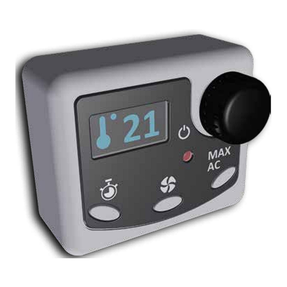
  • Page 56: Pannello Comandi

    IT EN FR DE ES PANNELLO COMANDI CONTROL PANEL PANNEAU DE COMMANDES SCHALTBRETT PANEL DE MANDOS 56/94...
  • Page 57: Pannello Comandi - Fissaggio

    IT EN FR DE ES PANNELLO COMANDI - FISSAGGIO CONTROL PANEL - FASTENING PANNEAU DE COMMANDES - FIXATION SCHALTBRETT - BEFESTIGUNG PANEL DE MANDOS - FIJACIÓN 1 = B 2 = N 3 = R 4 = L 57/94...
  • Page 58: Note E Avvertenze Generali

    IT EN FR DE ES Durante le fasi di montaggio, forando delle parti del veicolo, prestare ITALIANO attenzione a non danneggiare cablaggi o tubazioni di impianti già installati in precedenza. IMPORTANTE SIGILLARE ACCURATAMENTE CON PRODOTTO ADEGUATO OGNI FORO PRATICATO SULLE PARETI DEL VEICOLO. Prima di installare l'impianto verificare che: Il posizionamento dei tubi deve essere accurato, evitando curve strette, - sul veicolo sia presente l'impianto di aria condizionata di primo...
  • Page 59: Descrizione Generale / Caratteristiche Tecniche

    IT EN FR DE ES DESCRIZIONE GENERALE CARATTERISTICHE TECNICHE L’impianto fornito è un sistema di aria condizionata da stazionamento Potenza frigorifera 2800 W la cui caratteristica principale è la completa integrazione con l’impianto O.E. del veicolo; di conseguenza non viene pregiudicata l’estetica della cabina e non si perde l’utilizzo della botola.
  • Page 60: Componenti Forniti

    IT EN FR DE ES Descrizione Rif. Q.tà COMPONENTI FORNITI Pannello comandi Nastro biadesivo per fissaggio pannello comandi Centralina di controllo (ECU) Descrizione Rif. Q.tà Regolatore elettronico di velocità dell’elettroventola Gruppo compressore / separatore d’olio O.E. dell’evaporatore (versioni anno ˂ 2016) (fornito sciolto) Staffa di supporto gruppo compressore / separatore d’olio / condensatore...
  • Page 61: Installazione Condensatore E Gruppo Compressore

    Fissare il condensatore "C" alla staffa "E" (fig. 29 / 31). speciali e O.R. forniti "AK - AL - AQ - AR" (versioni con motore L6) (fig. 40 ÷ 46) / "AM - AN - AQ - AR" (versioni con motore V8 -520 cv-) (fig. 47, 48) / "AV - AW - AX - AQ - AR"...
  • Page 62: Dell'elettroventilatore O.e. Dell'evaporatore

    IT EN FR DE ES CARICA DI REFRIGERANTE Effettuare la carica di refrigerante a installazione completata dopo aver SCELTA DEL REGOLATORE ELETTRONICO DI VELOCITA' anche effettuato tutti i collegamenti elettrici. DELL'ELETTROVENTILATORE O.E. DELL'EVAPORATORE Vedi la sezione dedicata posta dopo le istruzioni per i collegamenti elettrici.
  • Page 63: Posizionamento Pannello Comandi

    IT EN FR DE ES Il passaggio dei cablaggi fra interno ed esterno può avvenire attraverso POSIZIONAMENTO PANNELLO COMANDI le aperture poste nella scatola elettrica (O.E.) (fig. 70 ÷ 72). Il collegamento all'alimentazione può essere effettuato sulla batteria Il pannello comandi "Y" (fig. 113) è l'interfaccia fra l'utente e l'impianto del veicolo.
  • Page 64: Carica Di Refrigerante

    IT EN FR DE ES CARICA DI REFRIGERANTE MANUTENZIONE E CONSIGLI PER L’USO Collegare la stazione di carica, effettuare il vuoto nel circuito ed eseguire La manutenzione dell'impianto fornito viaggia di pari passo a quella la precarica di refrigerante, quindi procedere con la ricerca di eventuali dell'impianto O.E.
  • Page 65: English

    IT EN FR DE ES During the assembly phases, when drilling into the vehicle parts, take ENGLISH care not to damage wiring or hoses of previously installed systems. CAREFULLY SEAL EVERY HOLE MADE IN THE VEHICLE WALLS USING A IMPORTANT SUITABLE PRODUCT.
  • Page 66: General Description / Technical Features

    IT EN FR DE ES GENERAL DESCRIPTION TECHNICAL FEATURES It's a parking cooler system and allows for full integration with the 1000 W (Std) vehicle's O.E. system; consequently, the interior aesthetics are not Cooling capacity compromised and the use of the hatch is not blocked. 2800 W (MAX AC) The airflow exploits the original vents of the vehicle, without using Fan speeds...
  • Page 67: Supplied Components

    IT EN FR DE ES Description Ref. Q.ty SUPPLIED COMPONENTS Control panel Double-sided adhesive tape for control panel fastening Electronic Control Unit (ECU) Description Ref. Q.ty Electronic speed regulator of the O.E. electric fan of the Compressor / oil separator group evaporator (versions year ˂...
  • Page 68: Installation Of Condenser And Compressor Group

    “Q” clamp and the corresponding screws (Figs. 36, 37). bracket “B”. All versions For "R"-"S" versions, mount bracket "D" as in fig. 23; for "G" versions, Bring the G8 “G” and G10 “H” hoses to the O.E. compressor “100”. mount bracket "D" as in fig. 24.
  • Page 69: Coolant Filling

    IT EN FR DE ES COOLANT FILLING Fill with coolant when the installation is complete, after all the electrical CHOOSING OF THE ELECTRONIC SPEED REGULATOR connections have been completed. OF O.E. EVAPORATOR ELECTRIC FAN See the dedicated section after the instructions for electrical connections.
  • Page 70: Control Panel Positioning

    IT EN FR DE ES The passage of the wiring between inside and outside can be made CONTROL PANEL POSITIONING through the openings in the O.E. electrical box (Figs. 70 ÷ 72). The connection to the power supply can be made on the vehicle’s control panel “Y”...
  • Page 71: Coolant Filling

    IT EN FR DE ES COOLANT FILLING MAINTENANCE AND RECOMMENDATIONS FOR USE Connect the "filling station", create a vacuum in the circuit and pre-fill The maintenance of the supplied system runs alongside that of the with coolant, then look for any leaks. O.E.
  • Page 72: Garantie

    à cent (par ex : 101). fluide réfrigérant car il est facilement inflammable - à l’état liquide le fluide réfrigérant s’évapore quand il entre au contact Les références alphabétiques accompagnées d’un point (par ex: A.1) de l’atmosphère et congèle tout ce avec quoi il entre en contact.
  • Page 73: Description Générale / Caractéristiques Techniques

    O.E. du véhicule; par conséquent, l’esthétique de la cabine 2800 W (MAX AC) n’est pas altérée et on peut continuer à utiliser la trappe. Nb de vitesses de ventilation Le flux d’air exploite les buses d’origine du véhicule, sans utiliser de conduits ou de canalisations qui modifieraient l’esthétique et les...
  • Page 74: Composants Fournis

    Ruban adhésif double face pour la fixation du panneau de commandes Description Réf. Q.té Centrale électronique de contrôle (ECU) Régulateur électronique de vitesse du ventilateur O.E. Groupe compresseur / séparateur d’huile de l’évaporateur (versions année ˂ 2016) (fourni en Étrier de support pour groupe compresseur / séparateur...
  • Page 75: Installation Du Condenseur Et Du Groupe Compresseur

    Le cheminement doit être le plus droit possible, en évitant les Vérifier, sur la plaquette d’identification, la quantité nominale, courbes étroites ou les siphons. le type de réfrigérant et le type d’huile présente dans le circuit O.E. du véhicule. Vérifier, sur la plaquette d’identification, la quantité nominale, le type de réfrigérant et le type d’huile présente dans le circuit O.E.
  • Page 76: Choix Du Régulateur Électronique De Vitesse De

    GN et A (32 schéma électrique). Le branchement sur le + clé (10 sur le schéma électrique) peut être réalisé sur la plaque des relais et des fusibles O.E. (situés au-dessus de la boîte à gants côté passager). Intercepter le câble vert (V) indiqué...
  • Page 77: Positionnement Du Panneau De Commandes

    Sonde de température air interne Le branchement sur le + clé (10 sur le schéma électrique) peut être réalisé dans la zone située à droite du tableau de bord, au-dessus de Raccordement + clé la plaque de relais et des fusibles O.E., devant les jambes du passager.
  • Page 78: Charge De Réfrigérant

    Le système fourni utilise le réfrigérant du circuit O.E. du véhicule. Débrancher la station de charge. Il est opportun de vérifier au début de chaque saison que le réfrigérant est présent en quantité suffisante. Une carence de réfrigérant comporte généralement une réduction des performances. La vérification peut être effectuée en raccordant une station de charge et en contrôlant les...
  • Page 79: Deutsch

    Sie mit der Installation beginnen. Befestigen Sie die elektrischen Kabel gut und achten Sie besonders Für die Installation ist es wichtig, sich sorgfältig an die Anweisungen auf deren Verlauf entlang der Metallwände, die elektrisch leitend sind; im vorliegenden Handbuch zu halten.
  • Page 80: Allgemeine Beschreibung / Technische Eigenschaften

    Fernsteuerung zur Betreibung der Anlage. Es ist ein Standklimasystem, dessen Verwendung bei ausgeschaltetem Fahrzeug vorgesehen ist; bei in Betrieb befindlichem Fahrzeug kann es nicht eingeschaltet werden. Für die Details zum Betrieb siehe die ebenfalls mit der Anlage mitgelieferte “Betriebsanleitung”. 80/94...
  • Page 81: Im Lieferumfang Enthaltene Bauteile

    (Versionen V8 -560 cv-) Leitung G10 Spezial Druckanschluss (Versionen V8 -580 cv und Isolierrohr für Leitung G10 höher-) Spiralschutz (für Leitung G8 von Ölabscheider zu 30 cm Spezial Sauganschluss (Versionen V8 -580 cv und Kondensator) höher-) 180°-Anschluss für Leitung G8 (OUT Ölabscheider) OR-Ring Ø10.8...
  • Page 82: Installation Kondensator Und Verdichterblock

    Schrauben im oberen Bereich des Elektroventilators des Kondensators "B" montieren. befestigen (Abb. 36, 37). Bei den Ausführungen "R"-"S" den Bügel "D" wie in Abb. 23, bei den Alle Versionen Ausführungen "G" den Bügel "D" wie in Abb. 24 montieren. Die Leitungen G8 "G" und G10 "H" zum O.E.-Kompressor "100" führen.
  • Page 83: Wahl Des Elektronische

    IT EN FR DE ES Für die Verbindung der Leitungen mit den Anschlüssen siehe die Maßnahmen, die im Abschnitt "VERKLAMMERUNG DER LEITUNGEN" WAHL DES ELEKTRONISCHE GESCHWINDIGKEITSREGLERS beschrieben sind. DES ORIGINAL-ELEKTROVENTILATORS DES VERDAMPFERS Versionen Baujahr ˂ 2016 KÜHLMITTELBEFÜLLUNG Den elektronischen Regler "AC" Code 606701022.5 (lose geliefert) Führen Sie den Einfüllvorgang des Kühlmittels nach Abschluss der...
  • Page 84: Positionierung Schaltbrett

    Befestigung gedacht, um eine Befestigung auch an andersartigen Flächen ermöglichen. Das Schaltbrett "Y" (8 Elektroplan) wie auf den Fotos gezeigt positionieren (Abb. 74 - 75). Für die weiteren Einzelheiten wird auf den Das mitgelieferte spezielle doppelseitige Klebeband ermöglicht eine nächsten Abschnitt verwiesen.
  • Page 85: Kühlmittelbefüllung

    Während der Reinigung der Anlage sind die elektrischen Bauteile schützen. Die Klimaanlage sollte nicht über längere Zeit unbenutzt sein, sondern einmal monatlich für eine halbe Stunde, auch während der Winterzeit, in Betrieb genommen werden, da durch den Betrieb die Schmierung einiger Bauteile gewährleistet ist, die ansonsten trocken würden.
  • Page 86 IT EN FR DE ES CERRAR CUIDADOSAMENTE CON UN PRODUCTO ADECUADO TODOS ESPAÑOL LOS ORIFICIOS REALIZADOS EN LAS PAREDES DEL VEHÍCULO. La colocación de los tubos debe ser cuidadosa, evitando curvas IMPORTANTE cerradas, esquinas vivas o chapas que puedan causar daños en los mismos.
  • Page 87: Descripción General

    IT EN FR DE ES DESCRIPCIÓN GENERAL CARACTERÍSTICAS TÉCNICAS El equipo suministrado es un sistema de aire acondicionado de Potencia enfriamiento 2800 W aparcamiento cuya principal característica es la integración completa con la instalación O.E. del vehículo; como consecuencia no se perjudica la estética de la cabina y no se pierde el uso de la trampilla.
  • Page 88: Componentes Suministrados

    IT EN FR DE ES Descripción Ref. C.dad COMPONENTES SUMINISTRADOS Panel de mandos Cinta adhesiva doble para fijación panel mandos Centralita de control (ECU) Descripción Ref. C.dad Regulador electrónico velocidad Grupo compresor / separador de aceite electroventilador O.E. del evaporador (modelos año < 2016) (suministrado por separado) Brida de soporte grupo compresor /separador de aceite / condensador...
  • Page 89 Volver a conectar los dos tubos O.E. al compresor, interponiendo los Posteriormente conectar el cableado en dotación mediante el cableado racores especiales y O.R. en dotación "AK - AL - AQ - AR" (modelos con de alargador "W". motor L6) (fig. 40 ÷ 46) / "AM - AN - AQ - AR" (modelos con motor V8 Seguidamente conectar eléctricamente al cableado en dotación.
  • Page 90 IT EN FR DE ES Para la conexión de los tubos a los racores seguir el procedimiento ilustrado en la sección “MODO DE ENGATILLADO TUBOS". ELECCIÓN DEL REGULADOR ELECTRÓNICO DE VELOCIDAD DEL ELECTROVENTILADOR O.E. DEL EVAPORADOR Modelos año < 2016 CARGA DE REFRIGERANTE Utilizar el regulador electrónico "AC"...
  • Page 91 IT EN FR DE ES El paso de los cables entre el interior y el exterior se puede realizar a COLOCACIÓN PANEL DE MANDOS través de las aperturas situadas en la caja eléctrica (O.E.) (fig. 70 ÷ 72). La conexión a la alimentación puede ser realizada a la batería del El panel de mandos “Y"...
  • Page 92: Carga De Refrigerante

    IT EN FR DE ES Al mismo tiempo es oportuno comprobar el funcionamiento de los CARGA DE REFRIGERANTE electroventiladores condensador. En el momento en el que se activa la función AC se ponen en marcha Conectar la estación de carga, efectuar el vacío en el circuito y llevar a los electroventiladores del condensador con una velocidad que varía en cabo la precarga de refrigerante, luego proceder con la búsqueda de función de la presión en el interior del circuito.
  • Page 93 IT EN FR DE ES 93/94...
  • Page 94 80821618.1AC - ...619.1AC - ...658.1AC - ...662.1AC 80817829.1 - Gennaio 2020 80821618.1IB - ...619.1IB - ...658.1IB - ...662.1IB...

Ce manuel est également adapté pour:

SG

Table des Matières