Publicité

Les langues disponibles
  • FR

Les langues disponibles

Liens rapides

1. Introduction
At the end of its life cycle, dispose of this product in accordance with local and national disposal
regulations. Read the manual thoroughly before bringing this device into service
Thank you for buying the DVM860BL! Use this device to measure and test: AC & DC voltage & current (also with
optional clamp AC97), resistance, temperature, batteries, diodes, continuity and transistors.
2. Safety
The DVM860BL is developed in accordance with IEC1010-1 concerning safety requirements for electrical measuring
instruments with an overvoltage category (CAT III) 600V and pollution 2. Respect these safety prescriptions:
• Protect yourself against electroshocks.
• Do not use this device for any other application than those described in this manual.
• Make sure the device was not damaged in transit.
• Make sure the insulation of the test leads is not damaged and/or the wire itself is not exposed.
• Full compliance with safety standards can only be guaranteed if the device is used with the supplied test leads. If
necessary, they should be replaced with identical leads or leads with identical electric ratings. All test leads should
be in good working order.
• Select the right input jack, function and range before use.
• Never exceed the specified limit values for the various measurement ranges.
• Do not touch unused terminals when the meter is connected to a circuit.
• Place the range selector in the highest position if the value to be measured is unknown beforehand.
• Do not measure voltages > 600V above earth ground.
• Exercise extreme caution when working with voltages in excess of 60Vdc or 30Vrms AC. Keep your fingers behind
the probe barriers while using the device.
• Do not connect the leads to a voltage source while the function switch is in one of the following modes: current,
resistance, temperature, battery, diode, transistor or continuity.
• Disconnect all test leads from the circuit to be tested prior to selecting a different function or range.
• Do not use the meter in dusty environments or in the presence of flammable gases and steam.
• Have the device checked by a qualified technician in case of malfunction.
• Never use the meter if the back panel is not in place and firmly fixed.
• Do not use or store the device in areas exposed to direct sunlight, high temperatures or high humidity.
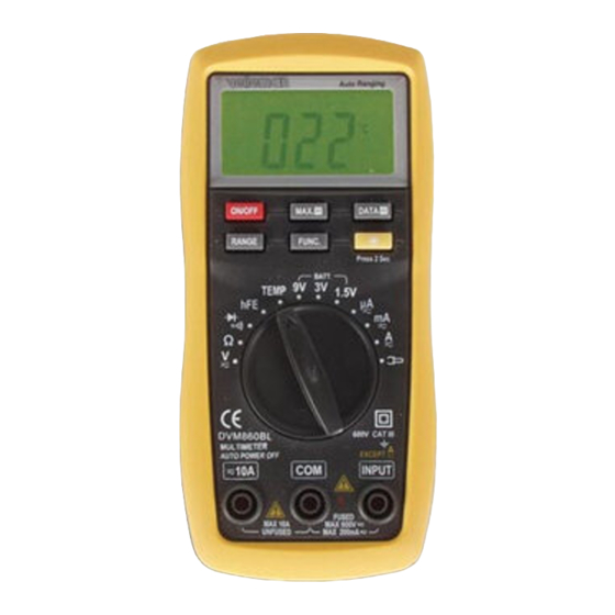
3. Device Description
a. Front Panel
1. LCD display
: allows readout of the measured values
2. ON/OFF button : used to activate / deactivate the device
3. RANGE button : used to select auto or manual range
4. FUNC. button : select AC or DC measurement, select °C or °F
5. Selector
: used to select the desired function and range
6. 10A jack
: input terminal for max. 10A current
7. INPUT jack
: input terminal (exception: 10A)
8. COM jack
9. Backlight button ( ) : to illuminates the LCD for a few seconds
10. DATA HOLD button
11. MAX HOLD button
DVM860BL
DVM860BL – DIGITAL MULTIMETER
: Displayed data are held
: Max. measured value is held
- 1 -
VELLEMAN

Publicité

Table des Matières
loading

Sommaire des Matières pour Velleman DVM860BL

  • Page 1 Read the manual thoroughly before bringing this device into service Thank you for buying the DVM860BL! Use this device to measure and test: AC & DC voltage & current (also with optional clamp AC97), resistance, temperature, batteries, diodes, continuity and transistors.
  • Page 2: General Specifications

    Automatic Power Off 15 minutes Power Supply 3 x 1.5V AAA-battery Operating Temperature 0°C to +40°C (+32 to +104°F) Storage Temperature -10°C to +50°C (+10 to +122°F) Dimensions 158 x 74 x 32mm Weight ±250g (batteries included) DVM860BL VELLEMAN - 2 -...
  • Page 3: Electrical Specifications

    : 200µ V, 20mA, 2A: 20mV, 2000µ A, 200mA, 10A-range: 200mV. 5.2.4. AC Current Range Resolution Accuracy 200µ A 0.1µ A ±1.5% of rdg + 5 digits 2000µ A 1µ A 20.00mA 0.01mA 200.00mA 0.1mA 2.000A 0.001A ±3.0% of rdg + 10 digits 10.00A 0.01A DVM860BL VELLEMAN - 3 -...
  • Page 4 50°F to 750°F ±1.0% of rdg ± 3 digits 400°C to 1000°C ±2.0% of rdg ± 3 digits 750°F to 1800°F ±2.0% of rdg ± 3 digits Overload Protection : 250V DC or AC rms DVM860BL VELLEMAN - 4 -...
  • Page 5: Battery Test

    6.2. Maximum Value Hold Button Press the MAX.H button during your measurements to display the highest value measured so far. Press the button again to remove the value from the display. DVM860BL VELLEMAN - 5 -...
  • Page 6: Range Selection

    3. Press the FUNC. button to select DC measurement. Select manual or auto range selection with the RANGE button. 4. Connect the test leads with the source or load under measurement. 5. Read the measured value from the LCD. The polarity of the red lead connection is also indicated. DVM860BL VELLEMAN - 6 -...
  • Page 7: Measuring Ac Voltage

    : the max. current for the INPUT jack is 200mA. The fuse will blow if the limit value is exceeded. The max. current for the 10A socket is 10A and this range is not fuse-protected. DVM860BL VELLEMAN - 7 -...
  • Page 8: Measuring Ac Current

    • Place the range selector in the highest position if the value to be measured is unknown beforehand. • Install the same range on the DVM860BL and the DC clamp. If the ranges do not match exactly, be careful not to exceed the limit values on the DVM860BL and the DC clamp of your choice: a.
  • Page 9: Measuring Resistance

    • Place the range selector in the highest position if the value to be measured is unknown beforehand. • Install the same range on the DVM860BL and the AC clamp. If the ranges do not match exactly, be careful not to exceed the limit values on the DVM860BL and the AC clamp of your choice: a.
  • Page 10: Diodetest

    2. Unscrew the cover of the battery compartment and remove it. 3. Remove the batteries and replace them. 4. Replace the cover and tighten the screws. Remark: Respect all applicable laws when disposing of your old batteries. DVM860BL VELLEMAN - 10 -...
  • Page 11: Accessories

    • thermocouple ("K"-type) • multifunction test socket The information in this manual is subject to change without prior notice. DVM860BL – DIGITALE MULTIMETER 1. Inleiding Ontdoe u, op het einde van zijn levensduur, van dit product volgens de plaatselijke en nationale regelgeving inzake verwijdering.
  • Page 12: Beschrijving Toestel

    Batterij / Batterij laag voldoet aan EU-richtlijnen Meting met (optionele) Buzzer voor continuïteit Diode stroomtang MAX.H DATA-H AUTO CATIII Maximumwaarde wordt Data op het scherm wordt Automatische selectie v/h Overspanningscategorie III, onthouden onthouden bereik vervuilingsgraad 2 (IEC1010-1) DVM860BL VELLEMAN - 12 -...
  • Page 13: Algemene Specificaties

    200V 0.1mV 600V Ingangsimpedantie : 10MΩ Bescherming tegen overbelasting : 250V DC of rms AC voor het 200mV-bereik, 600V DC of V rms AC voor de bereiken 2V tot 600V Max. ingangsspanning : 600V DC DVM860BL VELLEMAN - 13 -...
  • Page 14 Max. ingangsstroom : INPUT jack: 200mA, 10A jack: 10A. Spanningsval : 200µ V, 20mA, 2A: 20mV, 2000µ A, 200mA, 10A-bereik: 200mV. Frequentiebereik : 40 tot 400HZ Respons : gemiddeld, ijking in rms van een sinusgolf. DVM860BL VELLEMAN - 14 -...
  • Page 15 (±) Bescherming tegen overbelasting : F 200mA/250V zekering (quick-acting) voor de 1.5V & 3V bereiken, 250V DC of AC rms voor het 9V-bereik. Teststroom : ±50mA (1.5V bereik), ± 30mA (3V bereik), ±12mA (9V bereik) DVM860BL VELLEMAN - 15 -...
  • Page 16: Bedieningsinstructies

    RANGE knop om de manuele bereikinstelling te selecteren. Telkens u de knop indrukt, selecteert u één niveau hoger. Druk op de knop wanneer het hoogste bereik is ingesteld om het laagste bereik te selecteren. Houd de knop gedurende meer dan 2 seconden ingedrukt om terug te keren naar de automatische bereikinstelling. DVM860BL VELLEMAN - 16 -...
  • Page 17: Achtergrondverlichting

    • Bij het meten van lage spanningen kunt u op de LCD schommelende waarden uitlezen wanneer de meetsnoeren in de buurt komen van de schakeling in kwestie. U kunt deze waarden gewoon negeren: deze storing verdwijnt vanzelf zodra de meetsnoeren fysiek contact maken met de te testen schakeling. DVM860BL VELLEMAN - 17 -...
  • Page 18: Ac Stroom Meten

    3. Druk op de FUNC. knop om AC meting te selecteren. Selecteer manuele of automatische bereikinstelling met de RANGE knop. 4. Schakel de meetsnoeren in serie met de last die u wilt meten. 5. Lees de gemeten waarde af van de LCD. DVM860BL VELLEMAN - 18 -...
  • Page 19 • Plaats de bereikschakelaar in de hoogste stand indien u de waarde die u wilt meten niet op voorhand kent. • Stel hetzelfde bereik in op de DVM860BL en de DC stroomtang. Indien de bereiken elkaar slechts gedeeltelijk overlappen, dan moet u er extra over waken dat u de grenswaarden van geen van beide toestellen overschrijdt: a.
  • Page 20 3. Druk de FUNC. knop in om de functie "diodetest" te selecteren. 4. Verbind het rode meetsnoer met de anode en het zwarte meetsnoer met de kathode van de diode die u wilt testen. 5. Lees de waarde af van de LCD. DVM860BL VELLEMAN - 20 -...
  • Page 21: Continuïteit Testen

    1. De zekering moet slechts zelden worden vervangen en een gesprongen zekering is dikwijls het resultaat van een menselijke fout. 2. Schroef het batterijdeksel los, verwijder de oude zekering en breng een nieuwe in met identieke specificaties. 3. Breng het deksel weer aan. DVM860BL VELLEMAN - 21 -...
  • Page 22: Accessoires

    • thermokoppel ("K"-type) • multifunctionele adapterstekker De informatie in deze handleiding kan te allen tijde worden gewijzigd zonder voorafgaande kennisgeving. DVM860BL –MULTIMETRE NUMERIQUE 1. Introduction A la fin de sa durée de vie, débarrassez-vous de ce produit en respectant la législation d'élimination locale et nationale.
  • Page 23: Description De L'appareil

    • Enlevez les piles en cas d'une longue inactivité pour protéger l'appareil contre les fuites. 5. Spécifications L'appareil fonctionnera de façon optimale pendant les 12 mois après l'étalonnage. Les conditions d'utilisation idéales exigent une température de 18 à 28°C (64 à 82°F) et une humidité relative max. de 75%. DVM860BL VELLEMAN - 23 -...
  • Page 24: Spécifications Générales

    Protection contre les surcharges : 250V CC ou rms CAC pour la plage 200mV, 600V CC ou V rms CA pour les plages 2V à 600V Plage de fréquence : 40 à 400Hz Réponse : moyenne, réponse en rms d’une sinusoïde. Tension d'entrée max. : 600V rms CA DVM860BL VELLEMAN - 24 -...
  • Page 25 0 à 2000A 1A/1mV typique ±3.0% Protection contre les surcharges : 250V CC ou CA rms Tension d'entrée max. : 200mV Plage de fréquence : 40 à 400HZ Réponse : moyenne, réponse en rms d’une sinusoïde. DVM860BL VELLEMAN - 25 -...
  • Page 26: Test De Piles

    5.2.12. Transistor hFE Plage Fonction Lisez la valeur hFE (0-1000) du transistor testé (TOUS TYPES) sur l’afficheur Courant de base : ± 2µ A, Vce : ±1V Protection contre les surcharges : fusible F 200mA/250V (quick-acting) DVM860BL VELLEMAN - 26 -...
  • Page 27: Instructions D'opération

    3. Choisissez une fonction et une plage avec le sélecteur. Mettez le sélecteur dans la position max. si la plage n’est pas connue d’avance. 4. Connectez d’abord le cordon de mesure noir (masse) et puis le cordon de mesure rouge (+) pour éviter des électrochocs. DVM860BL VELLEMAN - 27 -...
  • Page 28: Mesurer Des Tensions Cc

    3. Sélectionnez des mesures CC avec le bouton FUNC. Instaurez la sélection de plage automatique ou manuelle avec le bouton RANGE. 4. Connectez les cordons de mesure en série avec la charge à mesurer. 5. La valeur mesurée et la polarité du cordon de mesure rouge sont affichées sur l’écran LCD. DVM860BL VELLEMAN - 28 -...
  • Page 29 • Placez le sélecteur de plage dans la position max. si la valeur à mesurer n’est pas connue d’avance. • Instaurez la même plage sur votre DVM860BL et le transducteur CC. Si les plages ne se recouvrent que partiellement, il faut faire très attention de ne pas dépasser les valeurs limites d'un des 2 appareils : a.
  • Page 30: Mesures De Résistances

    • Placez le sélecteur de plage dans la position max. si la valeur à mesurer n’est pas connue d’avance. • Instaurez la même plage sur votre DVM860BL et le transducteur CA. Si les plages ne se recouvrent que partiellement, il faut faire très attention de ne pas dépasser les valeurs limites d'un des 2 appareils : a.
  • Page 31: Test De Diodes

    être remplacée : 1. Déconnectez tous les cordons de mesure de sources sous tension, désactivez l’appareil et déconnectez les cordons de mesure des bornes d’entrée. 2. Dévissez et enlevez le couvercle du compartiment des piles. DVM860BL VELLEMAN - 31 -...
  • Page 32 CC y CA mediante la pinza aperimétrica opcional (p. ej. AC97 para corrientes CA). 2. Seguridad El DVM860BL cumple con la norma IEC-1010 de acuerdo con las disposiciones de seguridad para equipos de medición electrónicos con una categoría de sobrevoltaje (CAT II) y una clasificación de contaminación de grado 2.
  • Page 33: Descripción Del Panel Frontal

    • Contacte con un técnico cualificado en caso de un defecto. • Nunca use el multímetro, salvo que la cubierta posterior esté en su posición y firmemente cerrada. • No exponga el DVM860BL a la luz solar directa, temperaturas extremas o a la humedad. 3. Descripción del panel frontal a.
  • Page 34: Especificaciones Generales

    • Coloque el interruptor ON/OFF en la posición OFF si no usa el aparato. • Quite las baterías si no va a usar el DVM860BL durante un largo período de tiempo para evitar que las pilas tengan fugas. 5. Especificaciones Podría esperar una exactitud óptima durante 1 año después de la calibración.
  • Page 35 0.1mA 2.000A 0.001A ±3.0% lectura + 10 dígitos 10.00A 0.01A Protección de sobrecarga : fusible F 200mA/250V (quick-acting) para los rangos µ A y mA. Los rangos 2A y 10A no están protegidos por fusible. DVM860BL VELLEMAN - 35 -...
  • Page 36 ±1.0% lectura ± 3 dígitos 0.001k ±1.0% lectura ± 1 dígito 0.01k 200k 0.1k 0.001M 0.01M ±1.0% lectura ± 5 dígitos Tensión en circuito abierto : ±0.25V Protección de sobrecarga : 250V CC o CA rms DVM860BL VELLEMAN - 36 -...
  • Page 37 5.2.12. Transistor hFE Rango Función Lea el valor hFE (0-1000) del transistor probado (TODO LOS TIPOS) en la pantalla Corriente de base : ± 2µ A, Vce : ±1V Protección de sobrecarga : fusible F 200mA/250V (quick-acting) DVM860BL VELLEMAN - 37 -...
  • Page 38 3. Seleccione una función y un rango con el selector. Coloque el selector en la posición máx. si no conoce el rango de antemano. 4. Primero, conecte la punta de prueba negra (masa), luego, la punta de prueba roja (+) para evitar descargas eléctricas. DVM860BL VELLEMAN - 38 -...
  • Page 39 RANGE. 4. Conecte las puntas de prueba en serie con la carga que Ud. quiere probar. 5. El valor medido aparece en la pantalla. Se indica también la polaridad de la punta de prueba roja. DVM860BL VELLEMAN - 39 -...
  • Page 40 • Coloque el selector de rango en la posición máx. si no conoce el valor de antemano. • Seleccione el mismo rango en el DVM860BL y la pinza amperimétrica CC. Si los rangos no se igualan completamente, tenga mucho cuidado con no sobrepasar los valores límites de uno de los 2 aparatos : a.
  • Page 41 • Coloque el selector de rango en la posición máx. si no conoce el valor de antemano. • Seleccione el mismo rango para el DVM860BL y la pinza amperimétrica CC. Si los rangos no se igualan completamente, tenga mucho cuidado con no sobrepasar los valores límites de uno de los 2 aparatos : a.
  • Page 42: Prueba De Diodos

    4. El zumbador incorporado suena si hay continuidad. OBSERVACIONES • Se visualiza la indicación "OL" de sobrerango si la resistencia medida > 200Ω o si la entrada en cuestión no está conectada p.ej. en el caso de un circuito abierto. DVM860BL VELLEMAN - 42 -...
  • Page 43: Piezas De Recambio

    600V 10A. 8. Accesorios • puntas de prueba: máx. 600V / 10A • 3 x pila AAA de 1.5V • manual del usuario • funda de protección • sonda de tipo "K" • adaptador multifunción DVM860BL VELLEMAN - 43 -...
  • Page 44 Entsorgen Sie dieses Produkt gemäß der örtlichen und nationalen Gesetzgebung bezüglich Entsorgung. Lesen Sie diese Bedienungsanleitung vor Inbetriebnahme sorgfältig durch. Wir bedanken uns für den Kauf des DVM860BL! Sie können dieses Gerät zum Messen von Gleich- (DC) und Wechsel- spannung und –Strom (AC), Widerstand, Temperatur, Batterien, Dioden, Durchgang und Transistoren verwenden.
  • Page 45: Wartung Und Pflege

    "-" erscheint bei negativer Polarität Überlastungsanzeige "OL" Messeinheit Einheit von elektrischer Kapazität "Lo-Bat"-Anzeige " "-Symbol erscheint Max. Höhe 7000ft (2000m) Max. Spannung zwischen Eingangsbuchsen und Erdung 600V DC oder AC Sicherungsschutz F 200mA/250V (quick-acting) Automatische "Power Off"-Funktion 15 Minuten DVM860BL VELLEMAN - 45 -...
  • Page 46: Elektrische Spezifikationen

    Überlastungsschutz : F 200mA/250V Sicherung (quick-acting) für die µ A, mA Bereiche. Die 2A und 10A-Bereiche sind ohne Sicherung. Max. Eingangsstrom : Eingangsbuchse : 200mA, 10A Buchse : 10A. Spannungsabfall : 200µ V, 20mA, 2A : 20mV, 2000µ A, 200mA, 10A-Bereich : 200mV. DVM860BL VELLEMAN - 46 -...
  • Page 47 : durchschnittlich, Kalibrierung in rms der Sinuswelle 5.2.7. Widerstand Bereich Auflösung Genauigkeit ±1.0% ± 3 Digits 0.001k ±1.0% ± 1 Digit 0.01k 200k 0.1k 0.001M 0.01M ±1.0% ± 5 Digits Leerlaufspannung : ±0.25V Überlastungsschutz : 250V DC oder AC rms DVM860BL VELLEMAN - 47 -...
  • Page 48 : 250V DC oder AC rms 5.2.12. Transistor hFE Bereich Funktion der hFE-Wert (0-1000 des geprüften Transistors (ALLE TYPEN) erscheint im Display Basisstrom : ± 2µ A, Vce : ±1V Überlastungsschutz : F 200mA/250V Sicherung (quick-acting) DVM860BL VELLEMAN - 48 -...
  • Page 49 3. Selektieren Sie eine Funktion und einen Bereich mithilfe des Wahlschalters. Stellen Sie den Bereichsschalter in den höchsten Stand, wenn Sie die Belastungsintensität nicht im Voraus kennen. 4. Schließen Sie zuerst die schwarze Messleitung (mass) und zunächst die rote an um elektrische Schläge zu vermeiden. DVM860BL VELLEMAN - 49 -...
  • Page 50 3. Drücken Sie auf die FUNC-Taste um die Gleichstrom-Messungen zu selektieren. Wählen Sie die automatische oder manuelle Bereichswahl mit dem RANGE-Knopf. 4. Verbinden Sie die Messleitungen mit der zu prüfenden Quelle oder Last. 5. Lesen Sie den Messwert vom LCD-Display ab. Die Polarität der roten Messleitung wird auch angezeigt. DVM860BL VELLEMAN - 50 -...
  • Page 51: Wechselstrom Messen

    • Stellen Sie den Bereichsschalter in den höchsten Stand, wenn Sie die Belastungsintensität nicht im Voraus kennen. • Stellen Sie denselben Bereich für das DVM860BL und die DC-Stromzange ein. Wenn die Bereiche nicht genau übereinstimmen, achten Sie darauf, dass Sie die Grenzwerte des DVM860BL und der DC-Stromzange nicht überschreiten:...
  • Page 52 • Stellen Sie den Bereichsschalter in den höchsten Stand, wenn Sie die Belastungsintensität nicht im Voraus kennen. • Stellen Sie denselben Bereich für das DVM860BL als für die AC-Stromzange ein. Wenn die Bereiche nicht genau übereinstimmen, achten Sie darauf, dass Sie die Grenzwerte des DVM860BL und der AC-Stromzange nicht überschreiten:...
  • Page 53: Temperatur Messen

    5. Das eingebaute akustische Signal wird ertönen wenn es Durchgang gibt. ANMERKUNGEN • Die Überlastungsanzeige "OL" wird im Display erscheinen wenn der gemessene Widerstand > 200Ω ist oder wenn der Eingang nicht angeschlossen ist, z.B. im Falle eines offenen Kreislaufs. DVM860BL VELLEMAN - 53 -...
  • Page 54 Messgerät beiliegen. Wenn nötig, müssen Sie sie durch identische Messleitungen ersetzen. Elektrische Daten der Messleitungen: 600V 10A. 8. Zubehör • Messleitungen : max. 600V / 10A • 3 x 1.5V AAA (Mikro)-Batterie • Bedienungsanleitung • Holster • Thermoelement des K-Typs • multifunktionaler Adapter Alle Änderungen vorbehalten. DVM860BL VELLEMAN - 54 -...

Table des Matières