Table des Matières

Publicité

Les langues disponibles

Les langues disponibles

Liens rapides

Before returning this product call
1-800-4-D
INSTRUCTION MANUAL
GUIDE D'UTILISATION
MANUAL DE INSTRUCCIONES
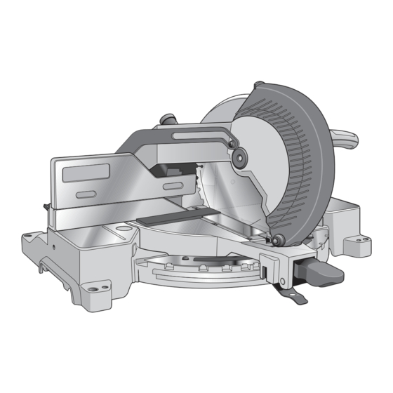
DW713
10" (254 mm) Compound Miter Saw
Scie à onglets mixtes de 254 mm (10 po)
Sierra ingletadora compuesta de 254 mm (10")
IF YOU SHOULD EXPERIENCE A PROBLEM WITH YOUR D
WALT
E
IF YOU HAVE A SUGGESTION OR COMMENT, GIVE US A CALL.
YOUR FEEDBACK IS VITAL TO THE SUCCESS OF D
Questions? Visit us at www.dewalt.com
CALL 1-800-4-D
IN MOST CASES, A D
WALT REPRESENTATIVE CAN RESOLVE
E
YOUR PROBLEM OVER THE PHONE.
IMPROVEMENT PROGRAM.
INSTRUCTIVO DE OPERACIÓN, CENTROS DE SERVICIO Y PÓLIZA DE
GARANTÍA. ADVERTENCIA: LÉASE ESTE INSTRUCTIVO ANTES DE
USAR EL PRODUCTO.
WALT PURCHASE,
E
WALT
E
WALT'S QUALITY
E

Publicité

Table des Matières
loading

Sommaire des Matières pour DeWalt DW713

  • Page 1 IF YOU HAVE A SUGGESTION OR COMMENT, GIVE US A CALL. YOUR FEEDBACK IS VITAL TO THE SUCCESS OF D WALT’S QUALITY IMPROVEMENT PROGRAM. Questions? Visit us at www.dewalt.com INSTRUCTION MANUAL INSTRUCTIVO DE OPERACIÓN, CENTROS DE SERVICIO Y PÓLIZA DE GUIDE D’UTILISATION GARANTÍA.
  • Page 2: Table Des Matières

    Table of Contents OPERATION .....……………………………………………………………………………8 DEFINITIONS: SAFETY GUIDELINES .................1 SWITCH ........................8 IMPORTANT SAFETY INSTRUCTIONS ................1 CUTTING WITH YOUR SAW ..................8 DOUBLE INSULATION/POLARIZED PLUG INSTRUCTIONS ..........1 CROSSCUTS .........................8 SAFETY INSTRUCTIONS FOR ALL TOOLS ....…………………………………………1 BEVEL CUTS .........................9 ADDITIONAL SAFETY RULES ..... ……………………………………………………….2 QUALITY OF CUT ......................9 ELECTRICAL CONNECTION .....…………………………………………………………3 BODY AND HAND POSITION ..................9...
  • Page 3: Definitions: Safety Guidelines

    • MAKE WORKSHOP CHILDPROOF with padlocks, master switches, or by removing Defi nitions: Safety Guidelines starter keys. The unauthorized start-up of a machine by a child or visitor may result in The definitions below describe the level of severity for each signal word. Please read the injury.
  • Page 4: Additional Safety Rules

    • CHECK for DAMAGED PARTS. Before further use of the tool, a guard or other part • NEVER CUT FERROUS METALS (Those with any iron or steel content) or masonry. that is damaged should be carefully checked to determine that it will operate properly and Either of these can cause the carbide tips to fly off the blade at high speeds causing perform its intended function—check for alignment of moving parts, binding of moving serious injury.
  • Page 5: Electrical Connection

    WALT Industrial Tool Co., 701 East Joppa Road, Baltimore, MD 21286, WHEN SERVICING, USE ONLY IDENTICAL RE PLACE MENT PARTS. call 1-800-4-D WALT (1-800-433-9258) or visit our website www.dewalt.com. ALWAYS WEAR EYE PROTECTION. DO NOT EXPOSE TO RAIN OR USE IN DAMP LOCATIONS.
  • Page 6: Specifications

    Check the contents of your miter saw carton to make sure that you have received all parts. In addition to this instruction manual, the carton should contain: END PLATE 1. One No. DW713 miter saw with blade. 2. One blade wrench in wrench pocket shown in Figure 2. 3. One No. DW7053 Dust Bag.
  • Page 7: Bench Mounting

    Bench Mounting IMPORTANT SAFETY INSTRUCTIONS Holes are provided in all four feet to facilitate bench mounting, as shown in Figure 2. (Two Changing or Installing a New Saw Blade (Fig. 3–5) different sized holes are provided to accommodate different sizes of screws. Use either hole, it WARNING: To reduce the risk of serious personal injury, turn off the tool and is not necessary to use both.) Always mount your saw firmly to prevent movement.
  • Page 8: Transporting The Saw

    5. Keeping the button depressed, use the other hand and the wrench provided to loosen FIG. 6 the blade screw. (Turn clockwise, left-hand threads.) 6. Remove the blade screw, outer blade clamp, and blade. The inner blade clamp may be left on the spindle.
  • Page 9: Bevel Stop

    Suggestion: For accuracy, set the top edge so that it aligns FIG. 10 FIG. 7 with zero. BEVEL STOP (FIG. 12, 13) To set the 45° bevel stop shown in Figure 12, first loosen the left side fence clamping knob and slide the left side fence as far as it will go to the left.
  • Page 10: Automatic Electric Brake

    FIG. 13 AUTOMATIC ELECTRIC BRAKE OPERATION LEFT SIDE LEFT SIDE Your saw is equipped with an automatic electric blade brake WARNING: To reduce the risk of serious personal BEVEL STOP FENCE which stops the saw blade within 5 seconds of trigger injury, turn off the tool and disconnect it from the SCREW CLAMPING...
  • Page 11: Bevel Cuts

    BEVEL CUTS (FIG. 12) FIG. 16A FIG. 16 A bevel cut is a crosscut made with the saw blade at a bevel to the wood. In order to set the bevel, loosen the bevel clamp knob and move the saw to the left as desired. (It is necessary to move the left side of the fence to allow clearance).
  • Page 12: To Install Clamp

    FIG. 17 For best results, use the DW7080 extension work support WARNING: A workpiece that is clamped, balanced and or the DWX723, DWX724 or DWX725B miter saw stand to secure before a cut may become unbalanced after a cut is extend the table width of your saw.
  • Page 13: Miter Scale

    WHEN MITERING TO THE LEFT The chart (Table 1) will assist you in selecting the proper FIG. 22 bevel and miter settings for common compound miter cuts. To increase the miter angle when mitering to the left, move To use the chart, select the desired angle “A” (Figure 19) of the arm to align the appropriate vernier mark with the closest your project and locate that angle on the appropriate arc in mark on the miter scale to the left.
  • Page 14: Cutting Crown Molding

    CUTTING 3.5" (88.9 mm)– 4.25" (107.95 mm) BASE MOLDING VERTICALLY INSIDE CORNER: OUTSIDE CORNER: AGAINST THE FENCE Left side Left side • Position molding as shown in Figure 21. 1. Position molding with top of molding 1. Position molding with bottom of the •...
  • Page 15: Special Cuts

    FIG. 27 FIG. 28 BEVEL SETTING TYPE OF CUT LEFT SIDE, INSIDE CORNER: 1. Top of molding against fence 33.85° 2. Miter table set right 31.62° 3. Save left end of cut RIGHT SIDE, INSIDE CORNER: 1. Bottom of molding against fence FENCE 33.85°...
  • Page 16: Maintenance

    For further detail of warranty DO NOT use lubricants or cleaners (particularly spray or coverage and warranty repair information, visit www.dewalt. aerosol) in the vicinity of the plastic guard. The polycarbonate com or call 1-800-4-D WALT (1-800-433-9258).
  • Page 17: Troubleshooting Guide

    Troubleshooting Guide BE SURE TO FOLLOW SAFETY RULES AND INSTRUCTIONS TROUBLE! WHAT’S WRONG? WHAT TO DO Saw will not start 1. Saw not plugged in 1. Plug in saw. 2. Fuse blown or circuit breaker tripped 2. Replace fuse or reset circuit breaker. 3.
  • Page 18 TABLE 1: COMPOUND MITER CUT (POSITION WOOD WITH BROAD FLAT SIDE ON THE TABLE AND THE NARROW EDGE AGAINST THE FENCE) SET THIS BEVEL ANGLE ON SAW...
  • Page 19 Table des matières DÉFINITIONS : LIGNES DIRECTRICES EN MATIÈRE DE SÉCURITÉ ......18 FONCTIONNEMENT ......................26 CONSIGNES DE SÉCURITÉ IMPORTANTES ..............18 DÉTENTE ........................26 INSTRUCTIONS RELATIVES À LA DOUBLE ISOLATION COUPE À L’AIDE DE VOTRE SCIE ................26 ET À LA FICHE POLARISÉE .....................18 COUPES TRANSVERSALES ..................
  • Page 20: Définitions : Lignes Directrices En Matière De Sécurité

    POUR TOUTE QUESTION OU TOUT COMMENTAIRE SUR CET OUTIL OU SUR pourrait se solder par des blessures corporelles. TOUT AUTRE OUTIL DeWALT, COMPOSER LE NUMÉRO SANS FRAIS SUIVANT : • PORTER LES VÊTEMENTS APPROPRIÉS. Ne pas porter ni vêtement ample, ni gant, 1-800-4-D WALT (1-800-433-9258).
  • Page 21: Règles De Sécurité Supplémentaires

    En cas de doute, utiliser le calibre supérieur suivant. Plus le numéro de calibre est petit, • SUIVRE TOUS LES CODES DE CÂBLAGE et les branchements électriques recommandés afin d’éviter les chocs électriques ou l’électrocution. Il faut protéger la ligne plus le cordon est de calibre élevé.
  • Page 22 • UTILISER UNIQUEMENT LES LAMES À TRONÇONNER recommandées pour AVERTISSEMENT : Toujours porter une protection auditive appropriée les scies à onglets. Pour des résultats optimums, ne pas utiliser de lames à pointes conformément à la norme ANSI S12.6 (S3.19) lors de l’utilisation du produit. Dans de carbure avec un angle d’attaque supérieur à...
  • Page 23: Connexion Électrique

    Road, Baltimore, MD 21286, États-Unis, composer le 1-800-4-D WALT (1-800-433-9258) ou DW7084 visiter notre site Web à www.dewalt.com. ACCESSOIRES FACULTATIFS (FIG. 1) LAMES DE SCIE : TOUJOURS UTILISER DES LAMES DE SCIE DE 254 mm (10 po) Les accessoires suivants, conçus pour votre scie, peuvent vous être utiles. Dans certains cas, COMPORTANT DES ALÉSAGES CENTRAUX DE 16 mm (5/8 po).
  • Page 24: Fiche Technique

    été livrées. En plus de ce mode d’emploi, le carton devrait contenir : Onglet à 50 °, à gauche ou à droite 1. Une scie à onglets no DW713 avec lame. Biseau de 48 ° à gauche; 3 ° à droite 2.
  • Page 25: Montage Sur Établi

    5. Maintenir le bouton enfoncé et utiliser l’autre main et la clé fournie pour desserrer la vis ATTENTION : Risque de pincement. Pour réduire le risque de blessures, garder le pouce de la lame. (Tourner dans le sens horaire, filets inversés.) sous la poignée lors de son abaissement.
  • Page 26: Réglages

    RÉGLAGE DU POINTEUR D’ONGLETS (FIG. 8, 9) FIG. 7 Afin de transporter aisément la scie à onglets d’un endroit Déverrouiller le levier de verrouillage d’onglet et presser à l’autre, l’outil est doté d’une poignée de transport sur la le loquet de l’onglet pour déplacer le bras d’onglet à la partie supérieure du bras de la scie, comme indiqué...
  • Page 27: Activation Et Visibilité Du Pare-Main

    Afin que la scie puisse biseauter JUSQU’À 48  ° vers la FIG. 13 FIG. 10 gauche, le côté gauche du guide peut être réglé afin de fournir VIS GAUCHE BOUTON DE le dégagement suffisant. Pour régler le guide, desserrer la DE BUTÉE DU BLOCAGE poignée, comme indiqué...
  • Page 28: Balais

    la ligne au crayon au bord coupé pour déterminer la direction RÉGLAGE DU DISPOSITIF DE VERROUILLAGE DE AVERTISSEMENT: Toujours porter une protection de réglage de l’angle d’onglet puis couper de nouveau. Il faut L’ONGLET (FIG. 15) oculaire. Tous les utilisateurs et spectateurs doivent porter un peu de pratique mais cette technique demeure toutefois La barre de verrouillage de l’onglet doit être réglée s’il est une protection oculaire conforme à...
  • Page 29: Fixation De La Pièce

    À BLANC (SANS ALIMENTATION) AVANT DE RÉALISER FIG. 16A FIG. 16 VOS COUPES AFIN DE VÉRIFIER LA TRAJECTOIRE DE LA LAME. NE PAS CROISER LES BRAS, COMME ILLUSTRÉ EN FIGURE 16A. Garder les pieds ancrés au sol afin de maintenir son équilibre.
  • Page 30: Soutien Des Pièces Longues

    La rainure logée dans la tige de la bride doit être bien FIG. 17 FIG. 18 DÉCOUPE DE MOULURES DE GARNISSAGE ET insérée dans la base. S’assurer que cette rainure est D’AUTRES CADRES bien insérée dans la base de la scie à onglets. Si la Le diagramme B de la figure 17 illustre un assemblage rainure est visible, cela signifie que la bride est mal fixée.
  • Page 31: Échelle À Onglets

    FIG. 22 DÉCOUPE DE MOULURES D’EMBASE Suivre la ligne horizontale intersectante jusqu’à l’un des deux axes pour obtenir le réglage de l’angle d’onglet pour votre TOUJOURS EFFECTUER UN ESSAI À BLANC SANS scie (42°). Suivre de même la ligne verticale intersectante ALIMENTATION AVANT D’ENTAMER TOUTE COUPE.
  • Page 32: Coupe De Moulures D'embase À Plat Avec La Fonctionnalité De Biseau

    • Toutes les coupes doivent être réalisées avec le dos de la moulure contre le guide COIN INTÉRIEUR : COIN EXTÉRIEUR : Côté gauche Côté gauche COIN INTÉRIEUR : COIN EXTÉRIEUR : 1. Positionner la partie supérieure de la 1. Positionner la face inférieure de la moulure Côté...
  • Page 33: Réglage Type De Coupe Du Biseau

    FIG. 27 FIG. 28 RÉGLAGE TYPE DE COUPE DU BISEAU CÔTÉ GAUCHE, COIN INTÉRIEUR: 1. Partie supérieure de la moulure contre le guide 33.85 ° 2. Table d’onglet définie à 31,62 ° 3. Conserver le côté gauche de la coupe GUIDE CÔTÉ DROIT, COIN INTÉRIEUR: TABLE 1.
  • Page 34: Coupes Spéciales

    31 et non comme le montre la le site www.dewalt.com ou composer le 1 800 433-9258 figure 32. Le fait de mal positionner le matériau entraînera le (1 800 4-D WALT).
  • Page 35: Guide De Dépannage

    AMÉRIQUE LATINE : cette garantie ne s’applique aux produits vendus en Amérique latine. Pour ceux-ci, veuillez consulter les informations relatives à la garantie spécifique présente dans l’emballage, appeler l’entreprise locale ou consulter le site Web pour les informations relatives à cette garantie.
  • Page 36: Réglez Cet Angle De Biseau Sur La Scie

    TABLEAU 1 COUPE À ONGLET MIXTE (POSITIONNEZ LE MORCEAU DE BOIS AVEC LE LARGE CÔTÉ PLAT CONTRE LA TABLE ET L’ARÊTE ÉTROITE CONTRE LE GUIDE.) RÉGLEZ CET ANGLE DE BISEAU SUR LA SCIE...
  • Page 37 Índice de temas DEFINICIONES: NORMAS DE SEGURIDAD ..............36 FUNCIONAMIENTO .. …………………………………………………………………………44 INSTRUCCIONES DE SEGURIDAD IMPORTANTES ............36 INTERRUPTOR......................44 INSTRUCCIONES SOBRE DOBLE AISLAMIENTO/ENCHUFE POLARIZADO ....36 CORTES CON LA SIERRA ..................44 INSTRUCCIONES DE SEGURIDAD PARA TODAS LAS HERRAMIENTAS .......36 CORTES TRANSVERSALES ..................44 REGLAS DE SEGURIDAD ADICIONALES .....…………………………………………37 CORTES BISELADOS ....................
  • Page 38: Definiciones: Normas De Seguridad

    • MANTENGA LIMPIA EL ÁREA DE TRABAJO. Los espacios y los bancos de trabajo Defi niciones: Normas de seguridad abarrotados propician accidentes. Las siguientes definiciones describen el nivel de gravedad de cada advertencia. Lea el manual • NO UTILICE LA MÁQUINA EN LUGARES PELIGROSOS. El uso de herramientas y preste atención a estos símbolos.
  • Page 39 La siguiente tabla muestra la medida correcta que debe utilizar según la longitud del cable • RESPETE TODOS LOS CÓDIGOS DE CABLEADO y las conexiones eléctricas y la capacidad nominal en amperios indicada en la placa. En caso de duda, utilice el recomendadas para prevenir los riesgos de descargas eléctricas o electrocución.
  • Page 40 • USE ÚNICAMENTE LAS HOJAS DEL TAMAÑO Y TIPO CORRECTOS especificados ADVERTENCIA: Algunas partículas de polvo generadas al lijar, serrar, esmerilar y para esta herramienta, a fin de prevenir daños a la máquina o lesiones graves. taladrar con herramientas eléctricas, así como al realizar otras actividades de construcción, •...
  • Page 41: Conexión Eléctrica

    WALT Industrial Tool Co., 701 East Joppa Road, Baltimore, MD 21286, llame al 1-800-4-D WALT (1-800-433-9258) o visite nuestro sitio web en www.dewalt.com. DW7084 ACCESORIOS OPCIONALES (FIG. 1) Los siguientes accesorios, diseñados para su sierra, pueden resultar útiles. En algunos casos, HOJAS DE SIERRA: SIEMPRE UTILICE HOJAS DE SIERRA DE 254 mm (10") CON...
  • Page 42: Especificaciones

    Además de este manual de instrucciones, la caja debe contener: Inglete a 50° a la izquierda y derecha 1. Una sierra ingletadora con hoja n. º DW713. Bisel a 48° a la izquierda: 3° a la derecha 2.
  • Page 43: Montaje En El Banco De Trabajo

    6. Retire el tornillo de la hoja , abrazadera externa de la hoja y la hoja. La abrazadera interna ATENCIÓN: Riesgo de pellizcos. Para reducir el riesgo de lesiones, mantenga el pulgar de la hoja pueden dejarse en el eje. debajo del mango cuando tire de éste hacia abajo.
  • Page 44: Ajustes

    Para transportar la sierra ingletadora fácilmente de un lugar REGULACIÓN DEL INDICADOR DE INGLETE FIG. 7 a otro, se ha incorporado un mango de transporte en la (FIG. 8, 9) parte superior del brazo de la sierra, como se muestra en Desbloquee la palanca de bloqueo de inglete y oprima la Figura 3.
  • Page 45: Regulación De La Guía

    REGULACIÓN DE LA GUÍA (FIG. 13) FIG. 13 FIG. 10 TORNILLO DE TOPE ADVERTENCIA: Para reducir el riesgo de lesiones, PERILLA DE DEL BISEL IZQUIERDO apague la herramienta y desconéctela de la fuente SUJECIÓN de alimentación antes de intentar moverla, cambiar DE LA GUÍA accesorios o hacer ajustes.
  • Page 46: Regulación Del Bloqueo De Inglete

    Asegúrese siempre de que la hoja se haya parado antes FUNCIONAMIENTO Para cortar siguiendo una línea marcada con lápiz sobre la pieza de madera, haga coincidir el ángulo de la forma de sacarla de la placa de corte. El freno no sustituye a los ADVERTENCIA: Para reducir el riesgo de lesiones, más precisa posible.
  • Page 47: Sujeción De La Pieza De Trabajo

    CORTES A FIN DE PODER CONTROLAR EL TRAYECTO FIG. 16A FIG. 16 DE LA HOJA. NO CRUCE LOS BRAZOS, COMO SE MUESTRA EN LA FIGURA16A. Mantenga ambos pies firmes sobre el piso y mantenga el equilibrio adecuado. Mientras usted mueve el brazo de inglete de izquierda a derecha, acompáñelo y párese al costado de la hoja de la sierra.
  • Page 48: Soporte De Piezas Largas

    Asegúrese de que esta ranura esté completamente FIG. 17 CORTE DE MOLDURAS DE TERMINACIÓN Y dentro de la base de la sierra ingletadora. OTROS MARCOS Si la ranura está visible, la abrazadera no estará segura. El esquema B de la Figura 17 muestra un empalme realizado con la regulación del brazo de inglete a 45°...
  • Page 49: Escala De Inglete

    INGLETE A LA IZQUIERDA EJEMPLO: Para hacer una caja de cuatro lados con FIG. 23 ángulos exteriores de 26° (Ángulo A, Figura 19), utilice el Para aumentar el ángulo de inglete al ingletar a la izquierda, arco derecho superior. Busque 26° en la escala del arco. mueva el brazo para alinear la marca de vernier adecuada con la marca más cercana en la escala de inglete a la Siga la línea de intersección horizontal hacia cualquiera de...
  • Page 50: Corte De Molduras De Corona

    CORTE DE 89 mm (3,5") A 108 mm (4,25") UNA MOLDURA DE BASE EN FORMA ESQUINA INTERIOR: ESQUINA EXTERNA: VERTICAL CONTRA LA GUÍA Lado izquierdo Lado izquierdo • Coloque la moldura como se muestra en la Figura 21. 1. Posición parte superior de la moldura 1.
  • Page 51 FIG. 27 FIG. 28 CONFIGURACIÓN TIPO DE CORTE DE BISEL LADO IZQUIERDO, ESQUINA INTERIOR: 1. Parte superior de la moldura contra el reborde 33,85° izquierda 2. Mesa de inglete a 31,62° a GUÍA la derecha 3. Conserve el extremo izquierdo MESA del corte MESA...
  • Page 52: Cortes Especiales

    MANTENIMIENTO Cortes especiales FIG. 31 GUÍA NO utilice lubricantes o limpiadores (especialmente NUNCA REALICE CORTES SIN QUE EL MATERIAL pulverizadores o aerosoles) cerca del protector de plástico. ESTÉ BIEN SUJETO A LA MESA Y CONTRA El policarbonato utilizado para el protector puede ser LA GUÍA.
  • Page 53: Garantía

    17 Norte #205 - Col. Centro (222) 246 3714 bajo garantía, visítenos en www.dewalt.com o dirígase al centro de servicio más cercano. Esta garantía no aplica a accesorios o a daños causados por reparaciones realizadas o QUERETARO, QRO intentadas por terceros.
  • Page 54: Guía Para Solucionar Problemas

    Guía para solucionar problemas ASEGÚRESE DE SEGUIR LAS REGLAS E INSTRUCCIONES DE SEGURIDAD PROBLEMA: ¿QUÉ SUCEDE? QUÉ HACER… La sierra no se enciende 1. La sierra no está enchufada 1. Enchufe la sierra. 2. Fusible quemado o interruptor automático activado 2.
  • Page 55: Fije Este Ángulo De Bisel En La Sierra

    TABLA 1: CORTE DE INGLETE COMPUESTO (UBIQUE LA MADERA CON EL LADO PLANO ANCHO SOBRE LA MESA Y EL BORDE ANGOSTO CONTRA EL REBORDE) FIJE ESTE ÁNGULO DE BISEL EN LA SIERRA...
  • Page 56 WALT Industrial Tool Co., 701 East Joppa Road, Baltimore, MD 21286 (AUG12) Part No. N126164 DW713 Copyright © 2007, 2009, 2012 D WALT The following are trademarks for one or more D WALT power tools: the yellow and black color scheme; the “D” shaped air intake grill; the array of pyramids on the handgrip; the kit box...

Ce manuel est également adapté pour:

N126164

Table des Matières