Table des Matières
Publicité
Les langues disponibles
Les langues disponibles
Liens rapides
Helios Ventilatoren
MONTAGE- UND BETRIEBSVORSCHRIFT
INSTALLATION AND OPERATING INSTRUCTIONS
NOTICE DE MONTAGE ET D'UTILISATION
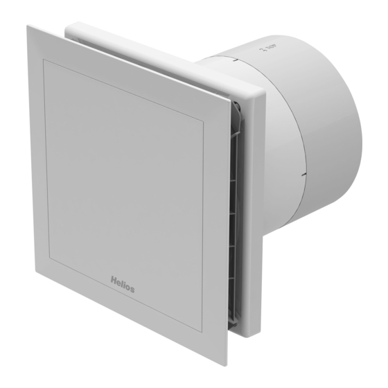
Kleinlüfter - Mini fan - Mini ventilateur
MiniVent M1/150 N / C
- mit zwei Leistungsstufen, codierbarem Nachlauf-/Intervallbetrieb
- equipped with two speeds, codable overrun timer/interval operation
- à 2 vitesses de fonctionnement, avec minuterie programmable
et temporisation
DE
EN
FR
Publicité
Chapitres
Table des Matières

Manuels Connexes pour Helios MiniVent M1 150 N C


Sommaire des Matières pour Helios MiniVent M1 150 N C
- Page 1 Helios Ventilatoren MONTAGE- UND BETRIEBSVORSCHRIFT INSTALLATION AND OPERATING INSTRUCTIONS NOTICE DE MONTAGE ET D‘UTILISATION Kleinlüfter - Mini fan - Mini ventilateur MiniVent M1/150 N / C - mit zwei Leistungsstufen, codierbarem Nachlauf-/Intervallbetrieb - equipped with two speeds, codable overrun timer/interval operation - à...
-
Page 2: Table Des Matières
DEUTSCH Inhaltsverzeichnis KAPITEL 1. SICHERHEIT ..............Seite 1 1.0 Wichtige Informationen . -
Page 3: Wichtige Informationen
Montage- und Betriebsvorschrift MiniVent M1/150 N / C Wichtige Informationen KAPITEL 1 Zur Sicherstellung einer einwandfreien Funktion und zur eigenen Sicherheit sind alle nachstehenden Vorschriften genau durchzulesen und zu beachten. SICHERHEIT Dieses Dokument ist Teil des Produktes und als solches zugänglich und dauerhaft aufzubewahren um einen sicheren Betrieb des Ventilators zu gewährleisten. -
Page 4: Einsatzbereich
Stillstandzeiten, starke Verschmutzung, übermäßige Beanspruchung durch klimatische, technische oder elekt- ronische Einflüsse geeignet. Gleiches gilt für die mobile Verwendung der Ventilatoren (Fahr-, Flugzeuge, Schiffe, usw.). Ein Einsatz unter diesen Bedingungen ist nur mit Einsatzfreigabe seitens Helios möglich, da die Serienausführung hier- für nicht geeignet ist. -
Page 5: Garantieansprüche - Haftungsausschluss
KAPITEL 2 Alle Ausführungen dieser Dokumentation müssen beachtet werden, sonst entfällt die Gewährleistung. Gleiches gilt für Haftungsansprüche an Helios. Der Gebrauch von Zubehörteilen, die nicht von Helios empfohlen oder angeboten ALLGEMEINE HINWEISE werden, ist nicht statthaft. Eventuell auftretende Schäden unterliegen nicht der Gewährleistung. Veränderungen und Umbauten am Gerät sind nicht zulässig und führen zum Verlust der Konformität, jegliche Gewährleistung und Haftung... -
Page 6: Berührungsschutz
Montage- und Betriebsvorschrift MiniVent M1/150 N / C Berührungsschutz - MiniVent M1/150 N / C Kleinventilatoren werden serienmäßig mit saugseitigem Schutzgitter geliefert. In Abhängigkeit der Einbauverhältnisse kann auch druckseitig ein Berührungsschutz erforderlich sein. Entsprechende Schutzgitter sind als Zu- behör lieferbar. - Ventilatoren, die durch ihre Einbauweise (z.B. -
Page 7: Funktionsbeschreibung M1/150 N / C
Montage- und Betriebsvorschrift MiniVent M1/150 N / C Funktionsbeschreibung M1/150 N / C KAPITEL 4 1. Einschaltverzögerung Der Ventilator schaltet sich erst nach der eingestellten Verzögerungszeit (0, 45, 90, 120 sec.) ein. So kann bei gemeins- FUNKTION amer Einschaltung mit dem Licht ein Raum kurzzeitig betreten werden, ohne dass der Ventilator in Betrieb geht. Die Einschaltverzögerung wird nur bei Stillstand des Ventilators durchgeführt. -
Page 8: Reinigung
Montage- und Betriebsvorschrift MiniVent M1/150 N / C Reinigung KAPITEL 5 GEFAHR! Durch einen Isolationsfehler können Sie einen elektrischen Schlag bekommen! REINIGUNG/ Vor Beginn der Reinigung Ventilator allpolig vom Netz trennen und gegen Wiedereinschalten sichern! DEMONTAGE – Fassade, Schutzgitter und sichtbare Gehäuseteile mit einem feuchten Tuch reinigen GEFAHR –... -
Page 9: Lieferumfang/Konstruktiver Aufbau
Montage- und Betriebsvorschrift MiniVent M1/150 N / C Alle nachfolgenden Informationen und Anweisungen sind nur für eine autorisierte Elektrofachkraft bestimmt! KAPITEL 6 Lieferumfang/Konstruktiver Aufbau Entnehmen Sie die M1-Liefereinheit erst unmittelbar vor dem Einbau aus dem Karton, um mögliche Beschädigungen INSTALLATION und Verschmutzungen beim Transport sowie auf der Baustelle zu vermeiden. - Page 10 Montage- und Betriebsvorschrift MiniVent M1/150 N / C Abb.5 Empfohlener Abb.6 Kabelaustritt Kabelführung unter dem Gehäuse. beliebig 0...-360 °, ideal jeweils 45° min. 130 mm Möglicher Bohrlöcher Kabelaustritt- bereich 2. Bohrlöcher Gehäuse ansetzen Löcher markieren und abbohren und mit mind. zwei Befestigungsschrauben und Dübeln montieren. 3.
-
Page 11: Elektrischer Anschluss / Inbetriebnahme
Montage- und Betriebsvorschrift MiniVent M1/150 N / C Elektrischer Anschluss / Inbetriebnahme WARNUNG! WARNUNG Das drehende Laufrad kann Ihre Finger quetschen. Vor dem Inbetriebnehmen Berührungsschutz sicherstellen! GEFAHR! GEFAHR - Der elektrische Anschluss, bzw. die Erstinbetriebnahme darf nur von einer autorisierten Elektrofachkraft ent- sprechend den Angaben in den beiliegenden Anschlussplänen ausgeführt werden. -
Page 12: Einbau
Montage- und Betriebsvorschrift MiniVent M1/150 N / C Abb.10 Abb.9 â 8 mm â ù ò 1. Anschlussraumabdeckung ù auf Kunststoffgehäuse - Länge Einzeladern 135 mm stecken und festschrauben (Pos â) - Abisolierlänge 8 mm 2. Anschl. Fassade â aufstecken und einschnappen - Mantelleitung bündig mit Kabelkanal abisolieren Einbau Abb.11... -
Page 13: Funktionsbeschreibung M1/150 N / C
Montage- und Betriebsvorschrift MiniVent M1/150 N / C Funktionsbeschreibung M1/150 N / C KAPITEL 7 1. Klemmenbelegung FUNKTION FÜR INSTALLATEUR – Klemme N/L An die Klemmen N und L wird dauerhaft eine Betriebsspannung von 230V angeschlossen. – Klemme 1 Die Klemme 1 aktiviert die kleine Stufe –... -
Page 14: Funktionstest - Testmodus
Montage- und Betriebsvorschrift MiniVent M1/150 N / C 6. Intervallbetrieb Der Ventilator kann in einstellbaren Zeitabständen automatisch in Betrieb gesetzt werden. Die Zeitabstände können über Dip-Schalter 5 und 6 eingestellt werden. Im Intervallbetrieb entspricht die eingestellte Nachlaufzeit der Einschalt- dauer. Der Intervallbetrieb beginnt nach dem letzten Ausschaltvorgang. Die Bedarfslüftung ist dem Intervallbetrieb übergeordnet. -
Page 15: Schaltplanübersicht Für M1/150 N / C
Montage- und Betriebsvorschrift MiniVent M1/150 N / C Schaltplanübersicht für M1/150 N / C Abb.13... -
Page 16: Instandhaltung Und Wartung
Montage- und Betriebsvorschrift MiniVent M1/150 N / C Instandhaltung und Wartung KAPITEL 8 GEFAHR! Bei der Demontage werden spannungsführende Teile freigelegt, die bei Berührung zu einem elektrischen INSTANDHALTUNG UND Schlag führen. WARTUNG Vor der Demontage Ventilator allpolig vom Netz trennen und gegen Wiedereinschalten sichern! GEFAHR –... -
Page 17: Störungsursachen
– keine Spannung Netzspannung prüfen Anschluss nach Schaltplan überprüfen – Laufrad blockiert Blockade lösen, reinigen, ggf. Laufrad ersetzen – Motor blockiert Helios Kundendienst kontaktieren – Motor gerade abgeschaltet Einschaltschutz (15 sec.) abwarten Sicherung löst aus – Windungsschluss im Motor Helios Kundendienst kontaktieren –... - Page 18 Montage- und Betriebsvorschrift MiniVent M1/150 N / C Notizen:...
- Page 19 Montage- und Betriebsvorschrift MiniVent M1/150 N / C Notizen:...
- Page 20 ENGLISH Table of contents CHAPTER 1. SAFETY ..............Page 1 1.0 Important information .
-
Page 21: Important Information
Installation and Operation Instructions MiniVent M1/150 N / C Important information CHAPTER 1 In order to ensure complete and effective operation and for your own safety, all of the following instructions should be read carefully and observed. SAFETY This document should be regarded as part of the product and as such should be kept accessible and durable to ensure the safe operation of the fan. -
Page 22: Application
The MiniVent M1/150 N / C mini fans are suitable for conveying normal or slightly dusty (particle size < 10 µm), less ag- gressive and humid air, in moderate climates and in the range of their performance curves, see Helios sales documents / internet. -
Page 23: Warranty Claims - Exclusion Of Liability
All versions of this documentation must be observed, otherwise the warranty shall cease to apply. The same applies to liability claims against Helios. The use of accessory parts, which are not recommended or offered by Helios, is not GENERAL OPERA- permitted. -
Page 24: Protection Against Contact
Installation and Operation Instructions MiniVent M1/150 N / C Protection against contact - MiniVent M1/150 N / C mini fans are delivered with an intake-side protection guard as standard. Depending on the moun- ting conditions, protection against contact may also be required on the discharge side. Corresponding protection guards are available as accessories. -
Page 25: Functional Description M1/150 N / C
Installation and Operation Instructions MiniVent M1/150 N / C Functional description M1/150 N / C CHAPTER 4 1. Activation delay The fan only activates after the set delay time (0, 45, 90, 120 sec.). Thus a room can be entered in case of activation FUNCTION together with the light, without the fan going into operation. -
Page 26: Cleaning
Installation and Operation Instructions MiniVent M1/150 N / C Cleaning CHAPTER 5 DANGER! An insulation fault may result in electric shock! CLEANING/ Before cleaning, isolate the fan from the mains power supply and secure against being switched on again! DISMANTLING –... -
Page 27: Scope Of Delivery/Design
Installation and Operation Instructions MiniVent M1/150 N / C All subsequent information and instructions are intended solely for authorised electricians! CHAPTER 6 Scope of delivery/Design Leave the M1 delivery unit in its box until installation. Check that the fan is in good condition and has not been dama- ged in transit. - Page 28 Installation and Operation Instructions MiniVent M1/150 N / C fig.6 fig.5 Recommen- Cable runs under the casing. cable exit optional 0...-360°, ideally in each case 45° min. 130 mm Possible ca- Drill holes ble exit area 2. Drill holes Set casing against the wall, mark the holes and drill. Fasten with at least 2 screws and plugs. 3.
-
Page 29: Electrical Connection / Start-Up
Installation and Operation Instructions MiniVent M1/150 N / C Electrical connection / Start-up WARNING! WARNING The rotating impeller can crush fingers. Ensure protection against contact before starting up! DANGER! DANGER - The electrical connection and initial start-up are to be carried out in accordance with the relevant wiring diagram and are only to be carried out by a certified electrician. -
Page 30: Mounting
Installation and Operation Instructions MiniVent M1/150 N / C fig.10 fig.9 â 8 mm â ù ò 1. Place and screw terminal compartment cover ù on - Length of single conductors 135 mm plastic casing (Pos â) - Stripping length 8 mm 2. -
Page 31: Functional Description M1/150 N / C
Installation and Operation Instructions MiniVent M1/150 N / C Functional description M1/150 N / C CHAPTER 7 1. Terminal allocation FUNCTION FOR INSTALLER – Terminal N/L An operating voltage of 230V is permanently connected to terminals N and L. – Terminal 1 Terminal 1 activates the lower stage –... -
Page 32: Functional Test - Test Mode
Installation and Operation Instructions MiniVent M1/150 N / C 6. Interval operation The fan can be automatically operated in adjustable intervals. The intervals can be adjusted via DIP-switches 5 and 6. In interval mode, the set overrun time corresponds to the running time. Interval operation starts after the last switch- off process. -
Page 33: Circuit Diagram Overview For M1/150 N / C
Installation and Operation Instructions MiniVent M1/150 N / C Circuit diagram overview for M1/150 N / C fig.13... -
Page 34: Servicing And Maintenance
Installation and Operation Instructions MiniVent M1/150 N / C Servicing and maintenance CHAPTER 8 DANGER! When dismantling, live parts which may result in electric shock upon contact may be exposed. SERVICING AND MAIN- Before dismantling, isolate the fan from the mains power supply and secure against being switched on again! TENANCE DANGER –... -
Page 35: Fault Causes
Check connection according to circuit diagram – Impeller blocked Clear blockade, clean, replace impeller if necessary – Motor blocked Contact Helios customer services – Motor just switched off Wait for activation protection (15 sec.) Fuse blows – Short-circuited coil in motor Contact Helios customer services –... - Page 36 Installation and Operation Instructions MiniVent M1/150 N / C Notes:...
- Page 37 Installation and Operation Instructions MiniVent M1/150 N / C Notes:...
- Page 38 FRANÇAIS Sommaire CHAPITRE 1. SÉCURITÉ ..............Page 1 1.0 Informations importantes.
-
Page 39: Chapitre 1. Sécurité
DANGER Des dispositions particulières sont applicables pour l’utilisation, le raccorde- ment et le fonctionnement ; contacter Helios en cas de doute. Veiller à bien respecter les normes nationales, règlements de sécurité et instructions. Lors de la manipulation du ventilateur, veiller à bien respecter les règles de sécurité... -
Page 40: Domaine D'utilisation
à des contraintes techniques et électroniques, une demande d’approbation est requise par Helios : les modèles de série n’étant pas prévus pour cet usage. Idem pour le déplacement des ventilateurs (voitures, avions, bateaux, etc.). -
Page 41: Demande De Garantie - Réserves Du Constructeur
Toute demande de remplacement ou de réparation à titre gratuit sera déclinée en cas de non-respect des indications REMARQUES contenues dans la notice. L’utilisation d’accessoires, non fournis, non conseillés ou non proposés par Helios, est GÉNÉRALES interdite. Si ces consignes ne sont pas respectées, la garantie s’annule. Idem pour les réserves constructeur. -
Page 42: Chapitre 3. Données Techniques
Notice de montage et d’utilisation MiniVent M1/150 N / C Protection des données - Les MiniVent M1/150 N/C sont livrés de série avec une grille de protection à l’aspiration. Selon le type d‘installation, une grille de protection au refoulement peut être nécessaire : cette grille est disponible en accessoire. - Les ventilateurs installés dans un système déjà... -
Page 43: Chapitre 4. Fonctionnalités
Notice de montage et d’utilisation MiniVent M1/150 N / C Description des fonctionnalités M1/150 N / C CHAPITRE 4 1. Démarrage différé Le ventilateur possède un démarrage différé programmable (0, 45, 90, 120 sec.). Cela permet lors d’un raccordement FONCTIONNALITÉS à... -
Page 44: Chapitre 5. Entretien/Démontage
Notice de montage et d’utilisation MiniVent M1/150 N / C Entretien CHAPITRE 5 DANGER ! Un défaut d’isolation peut entraîner un risque d’électrocution ! ENTRETIEN/ Avant tout entretien, le ventilateur doit être hors tension et être protégé contre tout redémarrage intempestif! DÉMONTAGE –... -
Page 45: Chapitre 6. Installation
Notice de montage et d’utilisation MiniVent M1/150 N / C Toutes les informations et consignes suivantes sont destinées à un électricien qualifié, certifié et autorisé ! CHAPITRE 6 Kit d’utilisation/Montage apparent Ne déballer qu’au moment de l’installation, afin d’éviter tous dommages et salissures lors du transport ou sur le INSTALLATION chantier. - Page 46 Notice de montage et d’utilisation MiniVent M1/150 N / C Fig. 5 Fig. 6 Sortie de Introduction des câbles sous le boîtier. câbles conseillée : 0-360 °, angle idéal : 45° min. 130 mm Sortie Percement possible de câbles 2. Percements Positionner la virole, marquer l’emplacement des fixations et percer.
-
Page 47: Raccordement / Mise En Service
Notice de montage et d’utilisation MiniVent M1/150 N / C Raccordement électrique / Mise en service m AVERTISSEMENT ! AVERTISSEMENT La turbine rotative peut pincer les doigts. Avant la mise en service, se protéger contre tout contact accidentel ! DANGER ! DANGER - Le raccordement électrique et la première mise en service ne peuvent être effectués que par un électricien agréé... -
Page 48: Montage
Notice de montage et d’utilisation MiniVent M1/150 N / C Fig. 9 Fig. 10 À 8 mm À ù ò 1. Emboîter et visser (Pos â) le couvercle du bornier - Longueurs de chaque fils : 135 mm. de raccordement ù. - Dénuder le fils sur 8 mm. -
Page 49: Chapitre 7. Fonctionnalité Pour L'installateur
Notice de montage et d’utilisation MiniVent M1/150 N / C Description de la fonctionnalité M1/150 N / C CHAPITRE 7 1. Raccordement des bornes FONCTIONNALITÉS POUR L’INSTALLATEUR – Borne N/L La tension d’alimentation 230 V est branchée en permanence sur les bornes N et L. –... -
Page 50: Essai De Fonctionnement - Mode Test
Notice de montage et d’utilisation MiniVent M1/150 N / C 6. Temporisation Le ventilateur peut s’activer à différents intervalles de temps. Les intervalles de temps peuvent s’activer via les interrup- teurs DIP 5 et 6. La temporisation comprend la durée définie de la temporisation du démarrage. La minuterie démarre après le dernier cycle de fontionnement. - Page 51 Notice de montage et d’utilisation MiniVent M1/150 N / C Vue d’ensemble pour le plan de accordement pour M1/150 N / C Fig.13 / fontionnement 1 vitesse / fontionnement 2 vitesses LED disponible en vente pour fonctionnement 1 vitesse - Aucun temps - Temps sur niveau 1 - Temps sur niveau 2 - Temps sur les deux...
-
Page 52: Chapitre 8. Entretien Et Maintenance
Notice de montage et d’utilisation MiniVent M1/150 N / C Entretien et maintenance CHAPITRE 8 DANGER ! Lors du démontage, le contact des parties sous tension peut entraîner des chocs électriques. ENTRETIEN ET Avant le démontage, le ventilateur doit impérativement être hors-tension et protéger contre tout redémarrage MAINTENANCE intempestif ! DANGER... -
Page 53: Dysfonctionnements
électrique. – Turbine bloquée. Débloquer, nettoyer, remonter le ventilateur. – Moteur bloqué. Contacter le SAV de Helios. – Le moteur se déconnecte. Attendre la protection à l’allumage (15 sec.). Le fusible se déclenche – Court-circuit dans le moteur Contacter le SAV de Helios. - Page 54 Notice de montage et d’utilisation MiniVent M1/150 N / C Notes :...
- Page 55 Notice de montage et d’utilisation Notice de montage et d’utilisation MiniVent M1/150 N / C MiniVent M1/150 N / C Notes :...
- Page 56 HELIOS Ventilatoren GmbH + Co KG · Lupfenstraße 8 · 78056 VS-Schwenningen HELIOS Ventilateurs · Le Carré des Aviateurs · 157 av. Charles Floquet · 93155 Le Blanc Mesnil Cedex CH HELIOS Ventilatoren AG · Tannstrasse 4 · 8112 Otelfingen GB HELIOS Ventilation Systems Ltd.