Publicité
Les langues disponibles
Les langues disponibles
Publicité
Table des Matières

Manuels Connexes pour Aim TTi EX2020R


Sommaire des Matières pour Aim TTi EX2020R
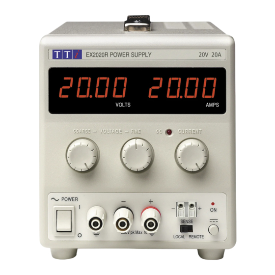
- Page 1 EX2020R Bench Power Supply INSTRUCTION MANUAL...
-
Page 2: Table Des Matières
Introduction The EX2020R is an exceptionally compact and lightweight single output laboratory dc power supply providing 0 to 20V at 0 to 20A. The EX2020R uses mixedmode regulation technology which combines switchmode preregulation with linear postregulation. Special techniques are used to maintain very high efficiency whilst achieving noise levels that are close to that of a pure linear regulator. -
Page 3: Specification
Specification OUTPUT Voltage Range: 0V to 20V minimum Current Range: 0A to 20A minimum Output Voltage Setting: By coarse and fine controls. Output Current Setting: By single logarithmic control. Operating Mode: Constant voltage or constant current with automatic cross-over. Output Switch: Electronic. -
Page 4: Safety
Safety This power supply is a Safety Class I instrument according to IEC classification and has been designed to meet the requirements of EN61010-1 (Safety Requirements for Electrical Equipment for Measurement, Control and Laboratory Use). It is an Installation Category II instrument intended for operation from a normal single phase supply. -
Page 5: Installation
Installation Mains Operating Voltage Check that the instrument operating voltage marked on the rear panel is suitable for the local supply. Mains Lead Connect the instrument to the AC supply using the mains lead provided. Should a mains plug be required for a different mains outlet socket, a suitably rated and approved mains lead set should be used which is fitted with the required wall plug and an IEC60320 C13 connector for the instrument end. -
Page 6: Operation
Operation Setting Up the Output With the POWER switch on ( ) and the output off the output voltage and current limit can be accurately preset using the VOLTAGE and CURRENT controls; the left-hand meter shows the set voltage and the right-hand meter shows the set maximum current. When the output switch is switched on, the ON lamp lights;... -
Page 7: Maintenance
Series or Parallel Connection with Other Outputs The outputs of the power supply are fully floating and may be used in series with other power supply units to generate high DC voltages up to 300V DC. The maximum permissible voltage between any terminal and earth ground ( ) is 300VDC. - Page 8 Sécurité Ce système alimentation est un instrument de classe de sécurité 1 conforme à la classification IEC et il a été conçu pour satisfaire aux exigences de la norme EN61010-1 (Exigences de sécurité pour les équipements électriques de mesure, de contrôle et d'utilisation en laboratoire). Il s'agit d'un instrument de Catégorie II d'installation devant être exploité...
- Page 9 Installation Tension d’utilisation secteur Vérifier que la tension opérationnelle de l'instrument indiquée sur le panneau arrière est appropriée pour l'alimentation locale. Câble secteur Branchez cet instrument sur l’alimentation secteur en utilisant le câble d’alimentation fourni. Si la prise murale requiert l’utilisation d’un câble d’alimentation différent, un câble approprié et approuvé, qui possède une fiche correspondante à...
- Page 10 Fonctionnement Réglage de la sortie L’interrupteur POWER (alimentation) sur ( ) et la sortie éteinte, il est possible de régler avec précision la limite de tension et de courant de sortie au moyen des commandes VOLTAGE (Tension) et CURRENT (Courant); l’appareil de mesure gauche indique la tension réglée et l’appareil droit le courant maximum réglé.
- Page 11 Connexion en série ou en parallèle avec d’autres sorties Les sorties de l’alimentation sont entièrement flottantes et elles peuvent être utilisées en série avec d’autres blocs d’alimentation, afin de produire des tensions c.c. jusqu’à 300 V c.c. La tension maximale admissible entre une borne et la terre ( ) est de 300 V c.c.
- Page 12 Sicherheit Diese Stromversorgung wurde nach der Sicherheitsklasse (Schutzart) I der IEC-Klassifikation und gemäß den europäischen Vorschriften EN61010-1 (Sicherheitsvorschriften für Elektrische Meß-, Steuer, Regel- und Laboranlagen) entwickelt. Es handelt sich um ein Gerät der Installationskategorie II, das für den Betrieb von einer normalen einphasigen Versorgung vorgesehen ist.
- Page 13 Installation Netzbetriebsspannung Sicherstellen, daß die auf der Geräterückwand angegebene Betriebsspannung mit der Versorgungsspannung am Ort übereinstimmt. Netzkabel Schließen Sie das Instrument unter Verwendung des mitgelieferten Netzkabels an die Wechselstromversorgung an. Falls ein Netzstecker für eine unterschiedliche Steckdose erforderlich ist, muss ein geeigneter zugelassener Netzkabelsatz verwendet werden, der mit der erforderlichen Steckdose und einem IEC60320 C13-Stecker für das Instrument versehen ist.
- Page 14 Betrieb Einstellung des Ausgangs Bei eingeschaltetem POWER-Schalter (Netz I) und ausgeschaltetem Ausgang läßt sich die Ausgangsspannung und Strombegrenzung mit Hilfe der Knöpfe VOLTAGE (Spannung) und CURRENT (Strom) genau voreinstellen. Die linke Anzeige zeigt die eingestellte Spannung und die rechte den eingestellten Maximalstrom an. Wenn der Ausgangsschalter eingeschaltet wird, leuchtet die ON (Ein)-Leuchte auf.
- Page 15 Abtastleitung gegeben ist. Dies lässt sich auf zweierlei Arten erreichen: entweder indem die Leitungen miteinander verdrillt werden oder indem ein koaxial geschirmtes Kabel (Abtastung über den Innerleiter) verwendet wird. Auch ein Elektrolytkondensator direkt am Lastanschlusspunkt kann hier von Nutzen sein. Der Spannungsabfall darf bei keiner Ausgangsleitung mehr als 0.5 Volt betragen.
- Page 16 Wartung Die Hersteller bzw. deren Vertretungen im Ausland bieten die Reparatur von Geräten an, bei denen eine Störung aufgetreten ist. Wenn der Eigentümer die Wartungsarbeiten selbst durchführen möchte, hat er dafür Sorge zu tragen, daß diese Arbeiten ausschließlich von entsprechend qualifiziertem Personal und gemäß Wartungshandbuch ausgeführt werden, das direkt von den Herstellern oder deren Vertretungen im Ausland bezogen werden kann.
- Page 17 Sicurezza Questo alimentatore appartiene alla Categoria di Sicurezza 1 secondo la classifica IEC ed è stato progettato in modo da soddisfare i criteri EN61010-1 (requisiti di Sicurezza per Apparecchiature di misura, controllo e per uso in laboratorio). È uno strumento di Categoria II di installazione e inteso per funzionamento con un’alimentazione normale monofase.
- Page 18 Installazione Tensione d’esercizio Controllare che la tensione d’esercizio dello strumento segnata sul pannello posteriore sia uguale a quella della rete elettrica locale. Cavo d’Alimentazione Collegare lo strumento all’alimentazione di rete in corrente alternata utilizzando il cavo fornito. Se dovesse essere necessaria una spina di alimentazione diversa, utilizzare un set completo della spina necessaria e di un connettore tipo IEC60320 C13 adeguatamente dimensionati e omologati.
- Page 19 Funzionamento Impostazione dell’uscita Con l’interruttore POWER (alimentazione) regolato su ( ) e l’uscita su off (spenta), la tensione di uscita ed il limite di corrente possono essere preimpostati accuratamente usando i comandi VOLTAGE (tensione) e CURRENT (corrente); il misuratore di sinistra mostra la tensione impostata mentre quello di destra indica la corrente massima impostata.
- Page 20 La caduta ohmica in ciascuno dei cavi di collegamento non deve superare 0,5V. Riportare l’interruttore LOCAL/REMOTE alla posizione LOCAL quando il rilevamento remoto non è usato. Collegamento in serie/parallelo con altre uscite Le uscite del dispositivo di alimentazione sono completamente flottanti e possono essere usate in serie con l’uscita di altri dispositivi si alimentazione per generare tensioni più...
- Page 21 Manutenzione I Produttori o i loro agenti all’estero faranno le riparazioni necessarie in caso di guasto. Qualora l’utente desiderasse eseguire il lavoro di manutenzione, tale lavoro deve essere fatto solo da personale qualificato e usando il manuale di servizio che può essere acquistato direttamente dai Produttori o dai loro agenti all’estero.
- Page 22 Seguridad Esta fuente de alimentación es un dispositivo de Clase de Seguridad I según la clasificación del IEC y ha sido diseñado para cumplir con los requisitos de la norma EN61010-1 (Requisitos de Seguridad para Equipos Eléctricos para la Medición, Control y Uso en Laboratorio). Es un instrumento de Categoría de Instalación II propuesto para ser usado con un suministro monofásico normal.
- Page 23 Instalación Tensión de la Red Eléctrica Verificar que la tensión de funcionamiento del instrumento que figura en el panel trasero concuerde con el suministro local. Cable de Red Conectar el instrumento al suministro de CA usando el cable de la red incluido. Si requiere un enchufe de la red para una toma de energía diferente, deberá...
- Page 24 Operación Ajuste de la Salida Con el interruptor POWER conectado ( ) y se pueden preajustar la salida de la tensión de salida y el límite de corriente con precisión usando los controles de VOLTAGE y CURRENT; el medidor a la izquierda indica la tensión ajustada y el medidor a la derecha indica la corriente máxima preajustada.
- Page 25 La caída de corriente en cada cable de salida no debe superar 0,5 V. Conmute el interruptor LOCAL/REMOTE de nuevo a LOCAL cuando no esté utilizando la detección remota. Conexión en Serie o en Paralelo a Otras Salidas Las salidas del suministro de fuerza son completamente flotantes y pueden emplearse en serie con otras unidades de suministro de fuerza para generar altos voltajes de CC de hasta 300V CC.
- Page 26 Mantenimiento Los fabricantes o sus agentes en el extranjero ofrecen un servicio de reparación para toda unidad que desarrolle un defecto. Si los propietarios desearan establecer su propio servicio, esto sólo debe realizarse por personas cualificadas en conjunto con el manual de servicio que puede adquirirse directamente del Fabricante o de sus agentes en el extranjero.
- Page 27 Thurlby Thandar Instruments Ltd. Glebe Road • Huntingdon • Cambridgeshire • PE29 7DR • England (United Kingdom) Telephone: +44 (0)1480 412451 • Fax: +44 (0)1480 450409 International web site: www.aimtti.com • UK web site: www.aimtti.co.uk Email: info@aimtti.com Aim Instruments and Thurlby Thandar Instruments...