Publicité

Les langues disponibles
  • FR

Les langues disponibles

Liens rapides

EX355R
Bench Power Supply
INSTRUCTION MANUAL

Publicité

Table des Matières
loading

Sommaire des Matières pour Aim TTi EX355R

  • Page 1 EX355R Bench Power Supply INSTRUCTION MANUAL...
  • Page 2: Table Des Matières

    Table of Contents Introduction Specification Safety Installation Connections Operation Maintenance Instructions en Francais Sécurité Installation Connexions Fonctionnement Maintenance Bedienungsanleitung auf Deutsch Sicherheit Installation Anschlüsse Betrieb Wartung Istruzioni in Italiano Sicurezza Installazione Collegamenti Funzionamento Manutenzione Instrucciones en Español Seguridad Instalación Conexiones Operación Mantenimiento...
  • Page 3: Introduction

    Introduction The EX355R is an exceptionally compact and lightweight single output laboratory dc power supply providing 0 to 35V at 0 to 5A. The EX355R uses mixed-mode regulation technology which combines switch-mode pre- regulation with linear post-regulation. Special techniques are used to maintain very high efficiency whilst achieving noise levels that are close to that of a pure linear regulator.
  • Page 4: Meter Specifications

    METER SPECIFICATIONS Meter Types: Dual 4 digit meters with 14mm (0.56") LEDs. Reading rate 4 Hz. Meter Resolutions: 10mV, 1mA Meter Accuracies: Voltage 0.3% of reading ± 3digits, Current 0.5% of reading ± 3digits GENERAL AC Input: 220V-240V AC ± 10%, 50/60Hz. 110V-240V AC ±...
  • Page 5: Ec Declaration Of Conformity

    Cambridgeshire PE29 7DR England declare that the EX355R Power Supply meets the intent of the EMC Directive 2004/108/EC and the Low Voltage Directive 2006/95/EC. Compliance was demonstrated by conformance to the following specifications which have been listed in the Official Journal of the European Communities.
  • Page 6: Emc

    This instrument has been designed to meet the requirements of the EMC Directive 2004/108/EC. Compliance was demonstrated by meeting the test limits of the following standards: Emissions EN61326-1 (2013) EMC product standard for Electrical Equipment for Measurement, Control and Laboratory Use. Test limits used were: Radiated: Class B Conducted: Class B...
  • Page 7: Safety

    Safety This power supply is a Safety Class I instrument according to IEC classification and has been designed to meet the requirements of EN61010-1 (Safety Requirements for Electrical Equipment for Measurement, Control and Laboratory Use). It is an Installation Category II instrument intended for operation from a normal single phase supply.
  • Page 8: Installation

    Installation Mains Operating Voltage Check that the instrument operating voltage marked on the rear panel is suitable for the local supply. Mains Lead When a three core mains lead with bare ends is provided this should be connected as follows: BROWN MAINS LIVE BLUE...
  • Page 9: Operation

    Operation Switching On The POWER switch is located at the bottom left of the front panel. When the POWER switch is turned on ( ) the right hand meter briefly indicates the firmware revision before the display shows Volts and Amps. Setting Up the Output With the POWER switch on ( ) and the...
  • Page 10: Maintenance

    Series or Parallel Connection with Other Outputs The outputs of the power supply are fully floating and may be used in series with other power supply units to generate high DC voltages up to 300V DC. The maximum permissible voltage between any terminal and earth ground ( ) is 300VDC.
  • Page 11: Sécurité

    Sécurité Cet instrument est de Classe de sécurité 1 suivant la classification IEC et il a été construit pour satisfaire aux impératifs EN61010-1 (impératifs de sécurité pour le matériel électrique en vue de mesure, commande et utilisation en laboratoire). Il s'agit d'un instrument d'installation Catégorie II devant être exploité...
  • Page 12: Installation

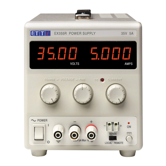
    Installation Tension d’utilisation secteur Vérifier que la tension opérationnelle de l'instrument indiquée sur le panneau arrière est appropriée pour l'alimentation locale. Câble secteur Relier de la manière suivante tout câble secteur à trois conducteurs à fils nus: MARRON SECTEUR SOUS TENSION BLEU SECTEUR NEUTRE VERT/JAUNE...
  • Page 13 Tension constante Les commandes VOLTAGE de réglage grossier et de précision permettent d’ajuster la tension de sortie; la commande CURRENT régle le courant maximum qui peut être fourni. Courant constant Si la résistance de charge est suffisamment basse qu’un courant supérieur au réglage de limite de courant puisse passer pour la tension de sortie réglée, l’alimentation passera automatiquement en mode de fonctionnement de courant constant.
  • Page 14: Maintenance

    Il faut noter que le bloc peut uniquement recevoir du courant, mais non le consommer, de sorte qu’il n’est pas possible de mettre en opposition de phase les blocs reliés en série. Il est possible de relier le bloc en parallèle avec d’autres, afin de produire des courants de haute intensité.
  • Page 15: Sicherheit

    Sicherheit Dieses Gerät wurde nach der Sicherheitsklasse (Schutzart) I der IEC-Klassifikation und gemäß den europäischen Vorschriften EN61010-1 (Sicherheitsvorschriften für elektrische Meß-, Steuer, Regel- und Laboranlagen) entwickelt. Es handelt sich um ein Gerät der Installationskategorie II, das für den Betrieb von einer normalen einphasigen Versorgung vorgesehen ist. Das Gerät wurde gemäß...
  • Page 16: Installation

    Installation Netzbetriebsspannung Sicherstellen, daß die auf der Geräterückwand angegebene Betriebsspannung mit der Versorgungsspannung am Ort übereinstimmt. Netzkabel Steht nur ein Netzkabel ohne Stecker zur Verfügung, so ist es wie folgt anzuschließen: BRAUN STROMFÜHRENDER LEITER BLAU NULLEITER GRÜN/GELB SCHUTZLEITER Schutzleitersymbol Bei Steckern mit eingebauten Sicherungen sollte eine 5 Ampere-Sicherung verwendet werden. Da die Farben der Netzkabeladern nicht unbedingt mit den Farbmarkierungen der Klemmen Ihres Steckers übereinstimmen, ist wie folgt vorzugehen: Die grün/gelbfarbene Ader ist an die mit E oder mit dem oben abgebildeten Schutzleitersymbol...
  • Page 17: Betrieb

    Betrieb Einschalten Der Netzschalter befindet sich unten links auf der Gerätevorderseite. Nach dem Betätigen des Netzschalters ( ) wird auf der rechten Anzeige kurz die Firmware-Version angezeigt, gefolgt von der Spannungs- und Stromanzeige. Einstellung des Ausgangs Bei eingeschaltetem POWER-Schalter (Netz I) und ausgeschaltetem Ausgang läßt sich die Ausgangsspannung und Strombegrenzung mit Hilfe der Knöpfe VOLTAGE (Spannung) und CURRENT (Strom) genau voreinstellen.
  • Page 18 Zu diesem Zweck müssen die SENSE-Klemmen mit dem Ausgang des Verbrauchers statt mit dem Ausgang der Quelle verbunden werden. Die Leitungen werden in die federbelasteten SENSE-Klemmen eingeführt und direkt an den Verbraucher angeschlossen. Der Fernbedienungsschalter (LOCAL/REMOTE) wird auf Fernbedienung (REMOTE) gestellt. Um Probleme bezüglich der Stabilität und des Einschwingverhaltens zu vermeiden, ist sorgfältig darauf zu achten, dass eine gute Kopplung zwischen dem jeweiligen Ausgang und der Abtastleitung gegeben ist.
  • Page 19: Wartung

    Wartung Die Hersteller bzw. deren Vertretungen im Ausland bieten die Reparatur von Geräten an, bei denen eine Störung aufgetreten ist. Wenn der Eigentümer die Wartungsarbeiten selbst durchführen möchte, hat er dafür Sorge zu tragen, daß diese Arbeiten ausschließlich von entsprechend qualifiziertem Personal und gemäß Wartungshandbuch ausgeführt werden, das direkt von den Herstellern oder deren Vertretungen im Ausland bezogen werden kann.
  • Page 20: Sicurezza

    Sicurezza Questo strumento appartiene alla Categoria di Sicurezza 1, secondo la classifica IEC, ed è stato progettato in modo da soddisfare i criteri EN61010-1 (requisiti di Sicurezza per Apparecchiature di misura, controllo e per uso in laboratorio). È uno strumento di Categoria d’installazione II ed è inteso per il funzionamento con un’alimentazione normale monofase.
  • Page 21: Installazione

    Installazione Tensione d’esercizio Controllare che la tensione d’esercizio dello strumento segnata sul pannello posteriore sia uguale a quella della rete elettrica locale. Cavo d’alimentazione Quando viene fornito un cavo a tre fili con le estremità nude, collegare come segue: MARRONE LINEA NEUTRO VERDE/GIALLO...
  • Page 22: Funzionamento

    Funzionamento Accensione L'interruttore di accensione (POWER) si trova in basso a sinistra sul pannello frontale. Quando è collocato su ( ) il manometro a destra indica brevemente la revisione del firmware prima che il display visualizzi i Volt e le Ampere di uscita. Impostazione dell’uscita Con l’interruttore POWER (alimentazione) regolato su ( ) e l’uscita...
  • Page 23 In questo caso i cavi di rilevamento devono essere collegati al carico e non alla sorgente: inserire i fili nei terminali SENSE caricati a molla e collegare direttamente al carico. Spostare l’interruttore LOCAL/REMOTE alla posizione REMOTE. Per evitare instabilità e problemi di risposta transitoria, si deve avere cura di ottenere un buon accoppiamento fra i morsetti d’uscita e i cavi di rilevamento o attorcigliando i cavi assieme o usando un cavo coassiale schermato (il filo di rilevamento dovrebbe essere quello interno).
  • Page 24: Manutenzione

    Manutenzione I Produttori o i loro agenti all’estero faranno le riparazioni necessarie in caso di guasto. Qualora l’utente desiderasse eseguire il lavoro di manutenzione, tale lavoro deve essere fatto solo da personale qualificato e usando il manuale di servizio che può essere acquistato direttamente dai Produttori o dai loro agenti all’estero.
  • Page 25: Seguridad

    Seguridad Este es un instrumento de Clase de Seguridad I según la clasificación del IEC y ha sido diseñado para cumplir con los requisitos del EN61010-1 (Requisitos de Seguridad para Equipos Eléctricos para la Medición, Control y Uso en Laboratorio). Es un instrumento de Categoría de Instalación II propuesto para ser usado con un suministro monofásico normal.
  • Page 26: Instalación

    Instalación Tensión de la Red Eléctrica Verificar que la tensión de funcionamiento del instrumento que figura en el panel trasero concuerde con el suministro local. Cable de Red Cuando se suministra un cable de tres conductores con puntas peladas, se deberá conectar como sigue: MARRON CORRIENTE DE RED...
  • Page 27: Operación

    Operación Puesta en marcha El interruptor de POWER (energía) está situado en la parte inferior izquierda del panel frontal. Al situar el interruptor POWER (energía) en ( ), el medidor derecho indica brevemente la revisión del soporte lógico antes de que el visualizador muestre los voltios y amperios. Ajuste de la Salida Con el interruptor POWER conectado ( ) y se pueden preajustar la salida...
  • Page 28 inestabilidad y problemas en la respuesta transitoria, se debe tener cuidado de asegurar un buen acoplamiento entre cada salida y cable del detector. Esto se puede lograr ya sea enroscando los cables juntos o usando un cable coaxial blindado (detector por el centro). Un condensador electrolítico directamente a través del punto de conexión de la carga también puede resultar beneficioso.
  • Page 29: Mantenimiento

    Mantenimiento Los fabricantes o sus agentes en el extranjero ofrecen un servicio de reparación para toda unidad que desarrolle un defecto. Si los propietarios desearan establecer su propio servicio, esto sólo debe realizarse por personas cualificadas en conjunto con el manual de servicio que puede adquirirse directamente del Fabricante o de sus agentes en el extranjero.
  • Page 30 Thurlby Thandar Instruments Ltd. Glebe Road • Huntingdon • Cambridgeshire • PE29 7DR • England (United Kingdom) Telephone: +44 (0)1480 412451 • Fax: +44 (0)1480 450409 International web site: www.aimtti.com • UK web site: www.aimtti.co.uk Email: info@aimtti.com Aim Instruments and Thurlby Thandar Instruments Book Part No.

Table des Matières