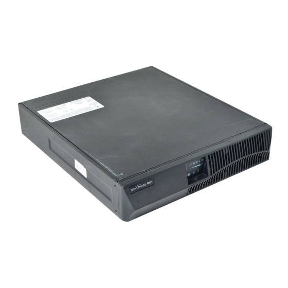
Eaton Powerware 9125 Guide D'installation
Pour applications ibm
Masquer les pouces
Voir aussi pour Powerware 9125:
- Guide d'installation (276 pages) ,
- Guide d'installation (270 pages)
Table des Matières
Publicité
Les langues disponibles
Les langues disponibles
Liens rapides
Publicité
Table des Matières

Manuels Connexes pour Eaton Powerware 9125


Sommaire des Matières pour Eaton Powerware 9125
- Page 2 Powerware y X-Slot son marcas comerical registradas de Eaton Electrical Inc. ECopyright 2006 Eaton Corporation, Raleigh, NC, USA. All rights reserved. No part of this document may be reproduced in any way without the express written approval of Eaton Corporation.
- Page 4 Symboles Spéciaux Voici des exemples de symboles utilisés sur l’onduleur ou ses accessoires pour vous alerter concernant des informations importantes : RISQUE DE CHOC ELECTRIQUE - Indique la présence d’un risque de choc électrique et l’avertissement associé devant être observé. ATTENTION : SE REPORTER AU MANUEL DE L’OPERATEUR - Reportez-vous à...
-
Page 9: Table Des Matières
..........® ® EATON Powerware 9125 (9910-P10, P11, P15, P16) UPS Installation Guide for IBM Applications... -
Page 25: Installation
164201633 Guide d’Installation Powerware 9125 (9910-P10, P11, P15, P16) Onduleur pour Applications IBM 164201514 Guide de l’Utilisateur de l’Onduleur Powerware 9125 Deux en Un (700–2000 VA) ® ® EATON Guide d’Installation Powerware 9125 (9910-P10, P11, P15, P16) Onduleur pour Applications IBM... -
Page 26: Connexion À La Batterie Interne De L'onduleur
Figure 2. Connexion du Connecteur de Batterie Interne Réinstallez le panneau avant de l’onduleur (voir Figure 3). Figure 3. Réinstallation du Panneau Avant ® ® EATON Guide d’Installation Powerware 9125 (9910-P10, P11, P15, P16) Onduleur pour Applications IBM 164201633 Rev A... -
Page 27: Configuration Et Installation
INSTALLATION Configuration et Installation L’onduleur Powerware 9125 s’adapte à diverses configurations et peut être installé en baie ou en tant qu’unité autonome. Si vous installez l’onduleur dans une baie, poursuivez avec la rubrique ci-dessous « Configuration en baie; » sinon, passez à la rubrique «... - Page 28 Passez à la rubrique « Installation de l’onduleur » à la page 20 pour terminer l’installation. Onduleur Modules optionnels Figure 5. L’Onduleur et modules EBM montés en baie ® ® EATON Guide d’Installation Powerware 9125 (9910-P10, P11, P15, P16) Onduleur pour Applications IBM 164201633 Rev A...
-
Page 29: Configuration En Tour
Figure 6. Fixez les supports à l’aide des vis fournies. Figure 6. Installation des supports de l’onduleur ® ® EATON Guide d’Installation Powerware 9125 (9910-P10, P11, P15, P16) Onduleur pour Applications IBM 164201633 Rev A... - Page 30 Redressez prudemment l’unité (voir Figure 8). Les grilles d’aération doivent être placées vers le haut. Grilles d’aération Figure 8. Configuration de type « tour » de l’onduleur et modules EBM ® ® EATON Guide d’Installation Powerware 9125 (9910-P10, P11, P15, P16) Onduleur pour Applications IBM 164201633 Rev A...
- Page 31 10. Passez à la rubrique « Installation de l’onduleur » pour terminer l’installation. Support de Liaison Onduleur Support de Liaison Figure 9. Installation des supports de liaison ® ® EATON Guide d’Installation Powerware 9125 (9910-P10, P11, P15, P16) Onduleur pour Applications IBM 164201633 Rev A...
-
Page 32: Installation De L'onduleur
Connecteur de Batterie de l’Onduleur Câble du EBM Connecteurs de Batterie de l’EBM Figure 10. Installation type de l’onduleur (modèle illustré : 120V) ® ® EATON Guide d’Installation Powerware 9125 (9910-P10, P11, P15, P16) Onduleur pour Applications IBM 164201633 Rev A... - Page 33 REMARQUE Si vous utilisez les segments de chargement, veuillez vous référer au Guide de l’Utilisateur de l’Onduleur Powerware 9125 Deux en Un (700–2000 VA) pour plus d’informations sur le contrôle et l’attribution des segments de chargement. REMARQUE NE PAS protéger les imprimantes laser avec l’onduleur, car les besoins en énergie des éléments chauffants sont exceptionnellement élevés.
-
Page 34: Surveillance De L'onduleur
électrique est défaillante. Avant de donner à QUPSDLYTIM la valeur « *NOMAX », assurez-vous de bien comprendre les implications de la fonction « *NOMAX » décrites sur le site Internet AS/400 Information Center. ® ® EATON Guide d’Installation Powerware 9125 (9910-P10, P11, P15, P16) Onduleur pour Applications IBM 164201633 Rev A... -
Page 35: Panneaux Arrières De L'onduleur
INSTALLATION Panneaux arrières de l’onduleur Les panneaux arrières des modèles de Powerware 9125 sont illustrés ci-dessous. Carte d’Interface Relais X-Slot Prises 5-15 Protecteur de transitoires pour réseau Connecteur de batterie Cordon d’alimentation Port REPO avec 5-15P Figure 11. Panneau arrière du modèle 1000–1500 VA, 120V Carte d’Interface Relais... -
Page 36: Service Après-Vente Et Assistance Technique
Figure 13. Exemple d’etiquettes de numéros de série IBM Commentaires Nous serons heureux de recevoir vos commentaires sur ce manuel. Veuillez envoyer vos questions ou suggestions d’améliorations à l’adresse ibm.ups@powerware.com. ® ® EATON Guide d’Installation Powerware 9125 (9910-P10, P11, P15, P16) Onduleur pour Applications IBM 164201633 Rev A... - Page 74 *164201633A* 164201633 A...