Table des Matières
Publicité
Les langues disponibles
Les langues disponibles
Liens rapides
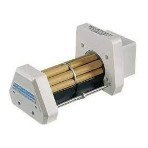
07519-15 Pump Head with 07519-75 Large Cartridge
Tête de pompe 07519-15 à cartouche épaisse 07519-75
Pumpenkopf 07519-15 mit großer Schlauchkassette 07519-75
Cabeza de bomba 07519-15 con cartucho grande 07519-75
Testa pompante 07519-15 con cartuccia grande 07519-75
Model Nos.
Modèles n°
Modellnummern
Números de modelo
Modelli n°
07519-10
07519-15
07519-20
07519-25
NOTE: This manual supersedes manual A-1299-0455,
which pertains to Cartridges 07519-55, -65.
®
Cole-Parmer Instrument Co.
11 (847) 549-7600 (Outside U.S.) (847) 549-7600 (Local) www.masterflex.com
1-800-MASTERFLEX (627-8373) (U.S. and Canada only)
Barnant Company
11 (847) 381-7050 (Outside U.S.) (847) 381-7050 (Local) www.barnant.com
OPERATING MANUAL
CARTRIDGE PUMP HEAD
SYSTEM
NOTICE D'UTILISATION
SYSTÈME DE TÊTE DE
POMPE À CARTOUCHES
BEDIENUNGSANLEITUNG
PUMPENKOPFSYSTEM
MIT SCHLAUCHKASSETTEN
MANUAL DE OPERACIÓN
SISTEMA DE CABEZA DE
BOMBAS DE CARTUCHOS
MANUALE DI ISTRUZIONI
SISTEMI CON TESTA
POMPANTE A CARTUCCE
Cartridge Small
Cartouche mince
Kleine Schlauchkassette
Cartucho pequeños
Cartucce piccole
07519-85
Cartridge Large
Cartouche épaisses
Grobe Schlauchkassette
Cartucho grandes
Cartucce grandi
07519-75
1-800-637-3739 (U.S. and Canada only)
A-1299-0905
Edition 02
Publicité
Chapitres
Table des Matières

Manuels Connexes pour Masterflex L/S 07519-10


Sommaire des Matières pour Masterflex L/S 07519-10
- Page 1 Cartridges 07519-55, -65. ® Cole-Parmer Instrument Co. 1-800-MASTERFLEX (627-8373) (U.S. and Canada only) 11 (847) 549-7600 (Outside U.S.) (847) 549-7600 (Local) www.masterflex.com Barnant Company 1-800-637-3739 (U.S. and Canada only) 11 (847) 381-7050 (Outside U.S.) (847) 381-7050 (Local) www.barnant.com...
-
Page 3: Table Des Matières
® Cole-Parmer Instrument Company 625 East Bunker Court Vernon Hills, Illinois U.S.A. 60061-1844 1-800-MASTERFLEX (627-8373) (U.S. and Canada only) 11 (847) 549-7600 (outside U.S.) (847) 549-7600 (Local) FAX (847) 247-2929 (U.S. and Canada only) 11 (847) 549-1700 (Fax outside U.S.) www.masterflex.com... -
Page 4: Safety Precautions
SAFETY PRECAUTIONS WARNINGS: Tubing breakage may result in fluid being sprayed from pump. Use appropriate measures to pro- tect operator and equipment. Turn off drive before removing or installing Cartridges. Safety guards are provided to minimize risk of fingers getting caught between the roller mechanism and the base of the module. However, be safe—Keep your fingers away from these areas. -
Page 5: Introduction
The instructions in this manual are task-oriented for easy reference. You can go directly to a particular section and ® ® quickly find the answers. Appendix A and B list MASTERFLEX pump drive types which can be used with this sys- tem. -
Page 6: Installation
Tool Required: Long hex key (provided). ® ® Mount the Pump Head to a MASTERFLEX Pump Drive as follows: 1. Connect the Pump to Drive by aligning the tang on Pump Head (see Figure 2) with the slot in the motor Drive shaft. -
Page 7: Setup
14, L/S 16, L/S 25 and L/S 17 in either six-roller pump head. Use only MASTERFLEX Precision Tubing and Microbore Tubing Sets with MASTERFLEX pumps to ensure optimum performance. Use of other tubing may void applicable warranties. (2) Load Cartridges The Cartridges’... - Page 8 FIGURE 4 REDUCED PULSATION CONNECTION WARNINGS: Tubing breakage may result in fluid being sprayed from pump. Use appropriate measures to pro- tect operator and equipment. Turn off drive before removing or installing Cartridges. Safety guards are provided to minimize risk of fingers getting caught between the roller mechanism and the base of the module.
-
Page 9: Cartridge Removal
Microbore Tubing Set. 7. Adjust the occlusion setting (see OPERATION section). For a nominal setting with MASTERFLEX tubing, turn ad- justment screw until inside edge of the wedge is aligned midway between #3 and #4 on the label. -
Page 10: Partial Bank Pumping
Using the range of oscillation observed in a ball type flowmeter as a measure, approximate relative pulsation values for any given tubing size and flow rate are shown in the following chart. The chart is based on using a three-roller ® ® MASTERFLEX pump as the benchmark with an arbitrary value of 10. ® ®... -
Page 11: Select Tubing And Pump Heads
Operating the pumps at speeds in excess of 250 rpm may result in premature wear of the pump rollers and tubing. TABLE 1 SMALL CARTRIDGE FLOW RATES—07519-85 ® ® MICROBORE TUBING SET (mm ID) MASTERFLEX TUBING Pump Drive Pump Head Units ®... -
Page 12: Select Pump Speed
Table 4. ® NOTE: With large and small cartridges, the scale identified as “Mflex” provides nominal occlusion for MASTERFLEX ® precision tubing at the #3 – #4 setting. With small cartridges only, the scale identified as “Micro” provides nominal oc- clusion for .9 mm (0.035 in) wall Microbore Tubing Sets at the #3 –... -
Page 13: Pump Overloading
(b) Occlusion Setting Procedure: 1. Select the recommended occlusion value from the table. 2. Turn the Occlusion Adjustment Knob to align the inside edge of the white Wedge with the scale number. (Clockwise rotation increases the occlusion.) (c) Optimized Occlusion Settings Some applications require additional fine-tuning of the occlusion setting to vary the flow rate for a particular tubing to re- duce flow variations caused by changes in system pressure, or to increase tubing life. -
Page 14: Specifications
(102 mm x 127 mm x 9.1 mm) WARRANTY Use only MASTERFLEX Precision Tubing and Microbore Tubing Sets with MASTERFLEX Pumps to ensure opti- mum performance. Use of other tubing may void applicable warranties. The Manufacturer warrants this product to be free from significant deviations from published specifications. If repair or adjustment is necessary within the warranty period, the problem will be corrected at no charge if it is not due to misuse or abuse on your part as determined by the Manufacturer. -
Page 15: L/S ® Pump Drive Types
APPENDIX A MASTERFLEX ® ® PUMP DRIVE TYPES FOR USE WITH CARTRIDGE PUMP SYSTEMS Power Torque Drive (hp) oz-in Type 1/10 1/20 1/20 1/10 NOTE: Check Max rpm and Power of the Drive or use the Torque rating to determine the Drive Type. - Page 16 ® ANNEXE A : Types d’entraînements de pompes MASTERFLEX ........26 ANNEXE B : Capacité...
-
Page 17: Mesures De Sécurité
MESURES DE SÉCURITÉ AVERTISSEMENTS : La rupture d’un tube peut entraîner une pulvérisation de liquide refoulé par la pompe. Prendre des mesures appropriées pour protéger l’opérateur et les appareils. Mettre l’entraînement hors tension avant de retirer ou de mettre en place des cartouches. Des disposi- tifs de protection sont prévus pour minimiser les risques de pincement des doigts entre le mécanisme à... -
Page 18: Introduction
Lorsqu’une telle surcharge se produit, l’embrayage émet un cliquetis audible pour indiquer que le rotor de la pompe ne tourne pas. ® ® La tête de pompe s’accouple rapidement à la plupart des types existants d’entraînements de pompes MASTERFLEX (voir les Annexes A et B). -
Page 19: Installation
® ® Accoupler la tête de pompe à un entraînement de pompe MASTERFLEX en procédant comme suit : 1. Accoupler la pompe à l’entraînement en alignant la queue de la tête de pompe (voir Figure 2) et la fente de l’arbre moteur. -
Page 20: Préparation
® ® ® La cartouche mince est conçue pour fonctionner avec les tubes de précision MASTERFLEX des calibres L/S 13 et L/S 14 dans l’une ou l’autre des têtes de pompes à six rouleaux et est également compatible avec des kits de tubes Microbore spécialement conçus (à... - Page 21 FIGURE 4 RACCORDEMENT À RÉDUCTION DE PULSATION AVERTISSEMENT : La rupture de tubulure risque d’entraîner la pulvérisation de liquide par la pompe. Prendre des mesures appropriées pour protéger l’opérateur et le matériel. Mettre l’entraînement hors tension avant de retirer ou de mettre en place des cartouches. Des disposi- tifs de protection sont prévus pour minimiser les risques de pincement des doigts entre le mécanisme à...
-
Page 22: Retrait D'une Cartouche
7. Ajuster le réglage d’occlusion (voir la section FONCTIONNEMENT). Pour obtenir le débit nominal en cas d’utilisation de tube MASTERFLEX, tourner la vis de réglage jusqu’à ce que le bord intérieur du coin soit aligné à mi-distance entre les chiffres 3 et 4 de la graduation. -
Page 23: Pompage Avec Bloc Partiel De Cartouches
à bille sont indiquées sur le tableau ci-dessous. Celui-ci est basé sur l’utilisation comme ® ® référence d’une pompe MASTERFLEX à trois rouleaux à laquelle est affectée arbitrairement une valeur de 10. Type de pompe... -
Page 24: Sélection Des Tubes Et Des Têtes De Pompes
07519-20 Non compatible 8 rouleaux ml/min 0,70 ml/min 07519-10 Non compatible 6 rouleaux ml/min TABLEAU 2 DÉBIT DES CARTOUCHES ÉPAISSES—07519-75 ® ® TUBES MASTERFLEX Vitesse Tête de Pompe d’entraînement ® ® ® ® pompe tr/mn Unités tr/mn DÉBITS ml/min... -
Page 25: Sélection De La Vitesse De Pompe
® ® l’occlusion nominale pour les tubes de précision MASTERFLEX entre les positions 3 et 4. Dans le cas des cartouches minces uniquement, la graduation identifiée par l’indication « Micro » permet d’obtenir l’occlusion nominale pour les kits de tubes Microbore à... -
Page 26: Surcharge De La Pompe
(b) Réglage de l’occlusion 1. Sélectionner la valeur d’occlusion recommandée en se reportant au tableau. 2. Tourner le bouton de réglage d’occlusion pour aligner le bord intérieur du coin blanc et le chiffre correct de la graduation. (Sa rota- tion dans le sens horaire augmente l’occlusion.) (c) Réglage de l’occlusion optimisée Certaines applications exigent un réglage supplémentaire de précision de l’occlusion afin de faire varier le débit pour un tube particu- lier, de réduire les variations de débit dues à... -
Page 27: Caractéristiques Techniques
9,1 mm GARANTIE N’utiliser que des tubes de précision MASTERFLEX et des kits de tubes Microbore avec les pompes MASTERFLEX pour garantir des performances optimales. L’utilisation de tout autre tube peut annuler les garanties applicables. Nous garantissons que ce produit est conforme aux descriptifs. Si une réparation ou un réglage s’avère nécessaire durant la période de garantie, le problème sera corrigé... -
Page 28: Annexe Atypes D'entraînements De Pompes Masterflex
ANNEXE A ® ® TYPES D’ENTRAÎNEMENTS DE POMPES MASTERFLEX COMPATIBLES AVEC LES SYSTÈMES DE POMPES À CARTOUCHES Vit. Max. Puissance Couple Type (tr/mn) kg•cm d’entraînement 74,6 1,27 37,3 1,27 37,3 0,635 74,6 2,54 REMARQUE : se référer à la vitesse max. et à la puissance de l’entraînement ou utiliser le couple nominal pour déterminer le type d’entraînement. - Page 29 ® Cole-Parmer Instrument Company 625 East Bunker Court Vernon Hills, Illinois U.S.A. 60061-1844 1-800-MASTERFLEX (627-8373) (U.S. and Canada only) 11 (847) 549-7600 (outside U.S.) (847) 549-7600 (Local) FAX (847) 247-2929 (U.S. and Canada only) 11 (847) 549-1700 (Fax outside U.S.) www.masterflex.com...
-
Page 30: Sicherheitsmassnahmen
SICHERHEITSMASSNAHMEN VORSICHT: Bei Schlauchbruch wird u. U. Flüssigkeit von der Pumpe verspritzt. Geeignete Maßnahmen zum Schutz von Bediener und Geräten ergreifen. Vor Herausnehmen oder Einsetzen von Schlauchkassetten den Antrieb ausschalten. Die vorhandenen Schutzvorrichtungen sollen nach Möglichkeit vermeiden, dass Finger zwischen die Rollenmechanismen und die Basis des Moduls geraten. -
Page 31: Einführung
Die Pumpenköpfe enthalten entweder sechs oder acht Rollen. Alle Modelle können mit verschiedenen Schläuchen verwendet ® ® werden. Die Modelle mit sechs Rollen sind mit der großen Kassette und dünnwandigem MASTERFLEX Schlauch, die Modelle mit acht Rollen mit der kleinen Schlauchkassette und Microbore-Schlauchsätzen mit einer 0,9 mm Wand kompatibel (siehe Tabellen 1, 2 und 3). -
Page 32: Installation
INSTALLATION Erforderliches Werkzeug: Langer Sechskantstiftschlüssel (im Lieferumfang enthalten) ® ® Der Pumpenkopf wird wie folgt am MASTERFLEX Pumpenantrieb montiert: 1. Zur Montage der Pumpe am Antrieb den Zapfen am Pumpenkopf (siehe Abbildung 2) an der Nut in der Pumpenantriebswelle ausrichten. -
Page 33: Vorbereitung
25 und L/S 17 in beiden Pumpenköpfen mit sechs Rollen. Um optimale Anwendungsergebnisse zu gewährleisten, sind für MASTERFLEX-PUMPEN ausschließlich MASTERFLEX-Präzisionsschläuche und Microbore-Schlauchsätze zu verwenden. Der Einsatz anderer Schläuche kann eine Verweigerung der Garantieleistung nach sich ziehen. (2) Einsetzen der Schlauchkassetten Die Anpressdruckoberflächen der Schlauchkassetten sind asymmetrisch um die Pumpenrolleneinheit positioniert (siehe... - Page 34 ABBILDUNG 4 SCHLAUCHANSCHLÜSSE ZUR PULSATIONSREDUZIERUNG VORSICHT: Bei Schlauchbruch wird u. U. Flüssigkeit von der Pumpe verspritzt. Geeignete Maßnahmen zum Schutz von Bediener und Geräten ergreifen. Vor Herausnehmen oder Einsetzen von Schlauchkassetten den Antrieb ausschalten. Die vorhandenen Schutzvorrichtungen sollen nach Möglichkeit vermeiden, dass Finger zwischen die Rollenmechanismen und die Basis des Moduls geraten.
-
Page 35: Herausnehmen Der Schlauchkassetten
Bei Verwendung eines Microbore-Schlauchsatzes gibt es keinen Durchhang. 7. Den Schlauchanpressdruck einstellen (siehe Abschnitt BETRIEB). Zur Einstellung auf den Nennwert bei Verwendung von MASTERFLEX-Schläuchen die Regulierschraube so drehen, dass die Innenkante des Keils mittig zwischen den Nummern 3 und 4 auf der Anzeige liegt. -
Page 36: Pumpenbetrieb Bei Teilweiser Belegung Der Schlauchkassettenaufnahme
Pulsationswerte für beliebige Schlauchgrößen und Fördermengen sind in der folgenden Tabelle enthalten. Zur Ermittlung ® ® der Werte in der Tabelle wurde eine MASTERFLEX Pumpe mit drei Rollen als Bezugsmaß und ein willkürlich gewählter Wert von 10 verwendet. Pumpentyp Kleine Große... -
Page 37: Wahl Der Schläuche Und Pumpenköpfe
Verwendung anderer Kombinationen kann es zu fehlerhaftem Betrieb oder Pumpenversagen kommen. Betreiben der Pumpen mit Drehzahlen von mehr als 250 U/min kann zu vorzeitigem Verschleiß der Pumpenrollen und des Schlauchs führen. TABELLE 1 FÖRDERMENGEN KLEINE SCHLAUCHKASSETTE – 07519-85 ® ® MICROBORE-SCHLAUCH (mm Innendurchmesser) MASTERFLEX SCHLAUCH Antrieb Pumpe Pumpenkopf U/min U/min Einheiten ®... -
Page 38: Wahl Der Pumpendrehzahl
Schlauch und Rollen führen. Den Schlauchanpressdruck nicht höher einstellen als in Tabelle 4 angegeben. ® ® HINWEIS: Der Nennwert für den Schlauchanpressdruck bei MASTERFLEX Präzisionsschläuchen liegt sowohl bei großen als auch bei kleinen Kassetten bei Einstellung 3 – 4 der mit „Mflex“ gekennzeichneten Skala. Der Nennwert für den Schlauchanpressdruck bei Microbore-Schlauchsätzen (Wandstärke 0,9 mm) liegt nur bei kleinen Kassetten bei Einstellung 3 –... -
Page 39: Überlastung Der Pumpe
(b) Schritte zur Einstellung des Schlauchanpressdrucks 1. Den empfohlenen Anpressdruckwert aus der Tabelle wählen. 2. Den Regulierknopf für den Schlauchanpressdruck so drehen, dass die Innenkante des weißen Keils auf gleicher Höhe mit der Skalennummer liegt. (Drehen im Uhrzeigersinn erhöht den Anpressdruck.) (c) Optimierte Anpressdruckeinstellungen Bei einigen Anwendungen muss die Annpressdruckeinstellung nachgestellt werden, um die Fördermenge für einen bestimmten Schlauch zu variieren oder die durch Änderungen im Systemdruck verursachten Fördermengenschwankungen zu reduzieren oder... -
Page 40: Technische Daten
GARANTIE Um optimale Anwendungsergebnisse zu gewährleisten, sind für MASTERFLEX-Pumpen ausschließlich MASTERFLEX-Präzisionsschläuche und Microbore-Schlauchsätze zu verwenden. Der Einsatz anderer Schläuche kann eine Verweigerung der Garantieleistung nach sich ziehen. Der Hersteller garantiert, dass dieses Produkt keine nennenswerten Abweichungen von den veröffentlichten Spezifikationen aufweist. -
Page 41: Anhang Bzulässige Anzahl Schlauchkassetten
ANHANG A ® ® MASTERFLEX PUMPENANTRIEBSTYPEN FÜR DEN EINSATZ MIT KASSETTENPUMPSYSTEMEN Max. Leistung Drehmoment Antriebstyp U/min kg•cm 74,6 1,27 37,3 1,27 37,3 0,635 74,6 2,54 HINWEIS: Den Antriebstyp anhand der max. U/min und Leistung oder des Nenndrehmoments des Antriebs bestimmen. - Page 42 ® APÉNDICE A TIPOS DE MANDOS DE BOMBA MASTERFLEX ........52 APÉNDICE B CAPACIDAD DE CARGA DE LOS CARTUCHOS.
-
Page 43: Precauciones De Seguridad
PRECAUCIONES DE SEGURIDAD ADVERTENCIAS: La rotura del tubo puede rociar fluido procedente de la bomba. Tome las medidas apropiadas para proteger al operador y los equipos. Apague el mando antes de quitar o instalar cartuchos. Se incluyen protectores de seguridad para reducir al mínimo el riesgo de que los dedos queden atrapados entre el mecanismo de los rodillos y la base del módulo. -
Page 44: Introducción
Cuando se produce una sobrecarga, el embrague produce un ruido audible indicando que el rotor de la bomba no está girando. ® ® La cabeza de la bomba se monta rápidamente en la mayoría de los tipos de mandos de bomba existentes MASTERFLEX (vea los Apéndices A y B). -
Page 45: Instalación
® ® Monte la cabeza de la bomba en un mando de bomba MASTERFLEX de la forma siguiente: 1. Conecte la bomba al mando alineando la lengüeta de la cabeza de la bomba (vea la Figura 2) con la ranura del eje del mando del motor. -
Page 46: Configuración
® ® ® El cartucho pequeño está diseñado para operar con tubos de precisión MASTERFLEX de tamaños L/S 13 y L/S 14 en la cabeza de bomba de seis rodillos y también permitirá... - Page 47 FIGURA 4 CONEXIÓN DE PULSACIONES REDUCIDAS ADVERTENCIAS: La rotura del tubo puede rociar fluido procedente de la bomba. Tome las medidas apropiadas para proteger al operador y los equipos. Apague el mando antes de quitar o instalar cartuchos. Se incluyen protectores de seguridad para reducir al mínimo el riesgo de que los dedos queden atrapados entre el mecanismo de los rodillos y la base del módulo.
-
Page 48: Desmontaje Del Cartucho
Microbore. 7. Fije el ajuste de oclusión (vea la sección de OPERACIÓN). Para un ajuste nominal con tubos MASTERFLEX, gire el tornillo de ajuste hasta que el borde interior de la cuña quede alineado a mitad de camino entre los números 3 y 4 de la etiqueta. -
Page 49: Bombeo Con Parte Del Grupo De Cartuchos
La tabla está basada en el uso de una bomba ® ® MASTERFLEX de tres rodillos como marca de referencia con un valor arbitrario de 10. Tipo de bomba... -
Page 50: Seleccione Los Tubos Y Cabezas De Bomba
No es compatible 8 rodillos ml/min 0,70 ml/min 07519-10 No es compatible 6 rodillos ml/min TABLA 2 CAUDALES DE CARTUCHOS GRANDES—07519-75 ® ® TUBOS MASTERFLEX Cabeza del rpm de rpm de ® ® ® ® mando impulsión la bomba Unidades CAUDALES... -
Page 51: Seleccione La Velocidad De La Bomba
2 Oclusión baja FIGURA 9A INDICACIONES DE OCLUSIÓN FIGURA 9B INDICACIONES DE OCLUSIÓN PARA LOS TUBOS MASTERFLEX PARA LOS JUEGOS DE TUBOS MICROBORE (a) Ajustes de oclusión normales La tabla siguiente muestra los ajustes de oclusión apropiados para proporcionar un rendimiento satisfactorio para diversos tamaños de tubos. -
Page 52: Sobrecarga De La Bomba
(b) Procedimiento de ajuste de oclusión 1. Seleccione el valor de oclusión recomendado de la tabla. 2. Gire la perilla de ajuste de oclusión para alinear el borde interior de la cuña blanca con el número de la escala. (El giro a la derecha aumenta la oclusión). -
Page 53: Especificaciones
9,1 mm de espesor GARANTÍA Use sólo tubos de precisión MASTERFLEX y conjuntos de tubo Microbore con bombas MASTERFLEX para asegurar un rendimiento óptimo. El uso de otros tubos puede anular las garantías correspondientes. El fabricante garantiza que este producto no se desvía significativamente con respecto a la especificaciones publicadas. Si es necesario efectuar reparaciones o ajustes en el período de garantía, el problema será... -
Page 54: L/S
APÉNDICE A ® ® TIPOS DE MANDOS DE BOMBA MASTERFLEX PARA USAR CON SISTEMAS DE BOMBAS DE CARTUCHOS Potencia Tipo de Máximas kg•cm mando 74,6 1,27 37,3 1,27 37,3 0,635 74,6 2,54 NOTA: Compruebe las rpm máximas y la potencia del mando o use el par nominal para determinar el tipo de mando. - Page 55 ® APPENDICE A — TIPI DI AZIONAMENTO DELLE POMPE MASTERFLEX ......65 APPENDICE B —...
-
Page 56: Misure Di Sicurezza
MISURE DI SICUREZZA ATTENZIONE: la rottura dei tubi può causare lo spruzzo del fluido dalla pompa; prendere le dovute precauzioni per proteggere l’operatore e l’attrezzatura. prima di montare o rimuovere le cartucce, spegnere l’azionamento; i dispositivi di sicurezza forniti riducono al minimo il rischio di avere le dita prese tra il meccanismo dei rulli e il basamento del modulo; tuttavia, per sicurezza, mantenere le dita a distanza. -
Page 57: Introduzione
Le istruzioni fornite in questo manuale si riferiscono a determinate funzioni e possono essere facilmente consultate direttamente nei ® ® relativi capitoli. Le appendici A e B elencano i tipi di azionamenti della pompa MASTERFLEX che possono essere usati con questo sistema. -
Page 58: Montaggio
Utensili necessari: una chiave esagonale lunga (in dotazione) ® ® Montare la testa pompante in un azionamento MASTERFLEX nel modo sottodescritto. 1. Collegare la pompa all’azionamento allineando il codolo nella testa pompante con la fessura nell’albero motore ( vedi Figura 2). -
Page 59: Messa A Punto
® ® ® La cartuccia piccola è stata progettata per l’uso con i tubi di precisione MASTERFLEX di dimensione L/S 13 e L/S 14 in una o l’altra testa pompante a sei rulli e può accettare anche i tubi Microbore progettati specificamente (parete di 0,9 mm) se si utilizza in una delle teste pompanti a otto rulli. - Page 60 FIGURA 4 COLLEGAMENTO CON PULSAZIONE RIDOTTA ATTENZIONE: la rottura dei tubi può causare lo spruzzo del fluido dalla pompa; prendere le dovute precauzioni per proteggere l’operatore e l’attrezzatura; prima di montare o rimuovere le cartucce, spegnere l’azionamento; i dispositivi di sicurezza forniti riducono al minimo il rischio di avere le dita prese tra il meccanismo dei rulli e il basamento del modulo;...
-
Page 61: Rimozione Della Cartuccia
è necessaria. 7. Regolare l’impostazione dell’occlusione ( vedi il capitolo sul FUNZIONAMENTO). Per regolare i tubi MASTERFLEX secondo il valore nominale, girare la vite regolatrice fino a quando il bordo interno del cuneo non sia allineato in un punto intermedio tra i valori n°... -
Page 62: Pompaggio Con Batteria Di Cartucce Parziale
La tabella si basa sull’uso di una pompa ® ® MASTERFLEX a tre rulli, come punto di riferimento con un valore arbitrario di 10. Tipo di pompa... -
Page 63: Selezione Di Tubi E Teste Pompanti
07519-20 Incompatibile a 8 rulli mL/min 0,70 mL/min 07519-10 Incompatibile a 6 rulli mL/min TAVOLA 2 PORTATA DI CARTUCCE GRANDI—07519-75 ® ® Giri/ TUBI MASTERFLEX Testa Giri/minuto minuto ® ® ® ® pompante dell’azionamento della Unità pompa PORTATE mL/min... -
Page 64: Selezione Della Velocità Della Pompa
® ® nominale dei tubi di precisione MASTERFLEX può essere impostata ai valori n°3 – n°4; per le cartucce piccole solamente, nella graduatoria denominata “Micro”, la regolazione dell’occlusione nominale dei tubi Microbore da 0,9 mm può essere impostata ai valori n°3 –... -
Page 65: Sovraccarico Della Pompa
(b) Istruzioni per l’impostazione dei valori dell’occlusione 1. Dalla tavola, selezionare il valore consigliato per regolare l’occlusione. 2. Girare la manopola regolatrice dell’occlusione per allineare il bordo interno del cuneo bianco con il valore nella graduatoria (la ro- tazione in senso orario aumenta l’occlusione). (c) Messa a punto di precisione dell’impostazione dei valori dell’occlusione Per alcuni impieghi occorre mettere a punto con precisione la regolazione dell’occlusione per variare la portata di un particolare tubo, ridurre le variazioni di flusso dovute alla variazione della pressione di sistema oppure per aumentare la durata dei tubi. -
Page 66: Specifiche Tecniche
9,1 mm GARANZIA Per le migliori prestazioni delle pompe MASTERFLEX, usare solo tubi di precisione MASTERFLEX e insieme di tubi Microbore. Usando altri tubi si rischia di invalidare le eventuali garanzie. Il produttore garantisce che questo prodotto non differisce in maniera significativa dalle specifiche tecniche pubblicate. In caso siano necessarie riparazioni o regolazioni entro il periodo di tempo in cui la garanzia è... -
Page 67: L/S
APPENDICE A ® ® TIPI DI AZIONAMENTO DELLE POMPE MASTERFLEX PER USO CON I SISTEMI DI POMPA A CARTUCCIA Potenza Coppia Tipppo di giri/min. kg•cm azionamento 74,6 1,27 37,3 1,27 37,3 0,635 74,6 2,54 NOTA: per determinare il tipo di azionamento, verificare i max giri/min e la potenza dell’azionamento oppure usare la coppia nominale.