Table des Matières

Publicité

Les langues disponibles
  • FR

Les langues disponibles

  • FRANÇAIS, page 138

Liens rapides

ULISSE RADICAL THERMAL
EN
English - Instructions manual
Italiano - Manuale di istruzioni
IT
Français - Manuel d'instructions
FR
Deutsch - Bedienungslanleitung
DE
Русский - Руководство по эксплуатации
RU
Thermal PTZ camera with up to 24x continuous zoom

Publicité

Table des Matières
loading

Sommaire des Matières pour Videotec ULISSE RADICAL THERMAL

  • Page 1 ULISSE RADICAL THERMAL Thermal PTZ camera with up to 24x continuous zoom English - Instructions manual Italiano - Manuale di istruzioni Français - Manuel d’instructions Deutsch - Bedienungslanleitung Русский - Руководство по эксплуатации...
  • Page 3 ENGLISH ULISSE RADICAL THERMAL Thermal PTZ camera with up to 24x continuous zoom English - Instruction manual...
  • Page 5: Table Des Matières

    Contents E N G L I S H 1 About this manual ........................6 1.1 Typographical conventions ..............................6 2 Notes on copyright and information on trademarks ............. 6 3 Safety rules..........................6 4 Identification ..........................9 4.1 Product description and type designation ........................9 4.2 Product marking ..................................
  • Page 6 8.1.1.3 How to modify the parameters ....................................22 8.1.1.4 How to change the numeric fields ..................................23 8.1.1.5 How to change text ........................................23 8.1.2 Configuration via OSM ..................................25 8.1.3 Main Menu .......................................25 8.1.4 Language Selection Menu..................................25 8.1.5 ZFI Parameter Menu .....................................25 8.1.5.1 Zone Titling Menu ........................................
  • Page 7 8.2.8 Preset Parameters page ..................................48 8.2.9 Preset Parameters page (Advanced) ...............................48 8.2.10 Digital I/O Page ....................................49 8.2.11 Camera Settings page ..................................50 8.2.12 Tools Page ......................................50 8.2.13 Thermal Camera menu ..................................50 8.2.14 Factory Default .....................................51 9 Accessories ..........................51 9.1 Wall mount bracket ................................51 9.2 Parapet bracket ..................................51 10 Instructions for normal operation ..................52 10.1 Visualizing the state of the pan &...
  • Page 8: About This Manual

    1 About this manual 3 Safety rules Read all the documentation supplied carefully before CAUTION! The electrical system to which installing and using this unit. Keep the manual in a the unit is connected must be equipped convenient place for future reference. with a 20A max automatic bipolar circuit breaker.
  • Page 9 • Before starting any operation, make sure the • This device was designed to be permanently power supply is disconnected. secured and connected on a building or on a suitable structure. The device must be permanently • Be careful not to use cables that seem worn or old. secured and connected before any operation.
  • Page 10 • Do not allow children or unauthorised people to • Take all necessary precautions to prevent the use the appliance. apparatus from being damaged by electrostatic discharge. • Only skilled personnel should carry out maintenance on the device. When carrying out •...
  • Page 11: Identification

    4.1 Product description and type Pan & tilt devices have a label complying with CE markings. designation ULISSE RADICAL THERMAL is the first Videotec ready- to-use thermal PTZ camera system that integrates exceptional factory-assembled combinations of lens and thermal camera for unsurpassed intrusion detection and visual awareness in total darkness or extreme environmental conditions.
  • Page 12: Preparing The Product For Use

    5 Preparing the product for 5.3 Contents Check the contents to make sure they correspond with the list of materials as below: Any change that is not expressly approved • Positioning unit by the manufacturer will invalidate the • Power supply base guarantee.
  • Page 13: Preparatory Work Before Installation

    5.5 Preparatory work before 5.5.2 Cables management installation The connection cables should not be accessible from the outside. It is necessary 5.5.1 Mounting the bracket to fasten the cables securely to the support in order to prevent excessive weight pulling Different types of supports are available (9 them out accidentaly.
  • Page 14: Connection Of The Cables To The Base

    6 Installation 6.1 Connection of the cables to the base Never, under any circumstances, make any changes or connections that are not Insert the cables into the cable glands holding the shown in this handbook. Failure to follow base at about 20cm from the support. Tighten the the connection instructions that are given cable glands.
  • Page 15: Fixing The Base To The Support

    6.2 Fixing the base to the support 6.3 Connector board description CONNECTOR BOARD DESCRIPTION Use the screws and the washers supplied with the base. Connector/ Function Component Once you have positioned the gasket (01), fix the Power supply for the board base (02) onto the bracket (03) with screws (04), Signal cables serrated washers (05) and screw rings (06).
  • Page 16: Connection Of The Power Supply Line

    6.4 Connection of the power Earth cable should be about 10mm longer supply line than the other two, so that it will not be disconnected accidentally if pulled. Depending on the version, the device can be provided with different power supply voltages. The The power supply cable must be covered power supply voltage is indicated on the product by the silicone sheath (01) supplied.
  • Page 17: 24Vac Power Line Connection

    6.4.1 24Vac power line connection 6.4.2 120Vac and 230Vac power line connection Use a Class 2 listed UL tranformer, Cut the cables to the correct length and make the compliant with the Standards in force, only connections. Connect the power supply to the for products marked UL, powered at 24Vac.
  • Page 18: Connection Of The Alarm Inputs And Relays

    6.4.3 Connection of the alarm inputs Version with LED illuminators and relays CONNECTION OF THE ALARM INPUTS, OF THE TWILIGHT SWITCH AND OF THE RELAYS CAUTION! TNV-1 installation type. The AL1, AL2, AL3, Self-powered alarm inputs referring to the installation is type TNV-1, do not connect it AL4 e ALARMS ALARMS common terminal to SELV circuits.
  • Page 19: Connecting The Telemetry Line

    6.7 Connecting the telemetry line 6.8 Fixing the upper body Fix the upper body (01) to the base (02) using the This chapter applies to analog models of fixing screws (03) equipped with gaskets (04). Make the product. sure the base seal is present and in good condition (05).
  • Page 20: Hardware Configuration

    OFF OFF OFF OFF ON DYNAMICS VISTA OFF OFF OFF ON OFF OFF ON Tab. 7 Configuration line RS232: MACRO (VIDEOTEC), 115200 baud, Address 1. This option does not require the Fig. 24 setting of the DIP-switch (DIP1, DIP3). MNVCUPKT_1838_EN...
  • Page 21: Dip3 Configuration

    6.9.4 DIP3 configuration 6.9.5 DIP4 configuration When the switch rocker is up it represents This DIP is set following the inverse the value 1 (ON). When the dip-switch procedure compared to those previously rocker is down it represents the value 0 performed.
  • Page 22: Switching On

    7 Switching on Make sure that all parts are fastened down firmly and safely. Make sure that the unit and other components of the installation are closed The automatic pre-heating (De-Ice) process so that it is impossible to come into contact could be started whenever the device is with live parts.
  • Page 23: Configuration

    8 Configuration 8.1.1.1 How to use the joystick All operations in the menus are carried out using the The videocamera on analog models of the joystick. product is configured via the OSM (8.1 OSM interface (On Screen Menu), page 21). The videocamera on IP models of the product is configured via the web page (8.2 Web interface, page 44).
  • Page 24: How To Move Around The Menus

    8.1.1.2 How to move around the menus 8.1.1.3 How to modify the parameters Each page of the OSM shows a list of parameters Move the cursor to the parameter to be changed and or sub-menus that can be selected by the operator. confirm.
  • Page 25: How To Change The Numeric Fields

    8.1.1.4 How to change the numeric fields 8.1.1.5 How to change text Move the cursor to the parameter to be changed and Move the cursor to the parameter to be changed and confirm. confirm. EDIT PRESET EDIT ZONE ------------------------ ------------------------ 1 NR.
  • Page 26 You can move inside the menu using the joystick. Use: • ERASE: Delete the whole text string. EDIT TEXT: AREA • SAVE: Save the new text before exiting the menu. ------------------------ • EXIT: Exit the menu. Text: TEXT AREA1 ↑ •...
  • Page 27: Configuration Via Osm

    8.1.2 Configuration via OSM 8.1.5 ZFI Parameter Menu The screens for the product setup are illustrated Zoom: This sets the maximum zoom level that below. the motorised lens can achieve. Common Wire: If enabled, it manages the 8.1.3 Main Menu motorised common wire lenses;...
  • Page 28: Zone Titling Menu

    8.1.5.1 Zone Titling Menu Example: To enable titling of zone 1 when the device is between +15° and +45°, it is necessary to: This function allows setting up to eight (variable • Enable area titling by setting Y as the value of dimension) areas with titling option.
  • Page 29: Zone Masking Menu

    8.1.5.2 Zone Masking Menu Example: To enable masking of zone 1 when the device is in the +15° and +45° position, proceed as This function allows setting up to eight masks follows: (variable dimension) with titling option. • Select 1 as value of parameter No. Number: Selects the area to be edited.
  • Page 30: Housing Serial Port Menu

    8.1.6 Housing Serial Port Menu 8.1.7 Polarity Menu It allows you to configure the following parameters: Once you have exited from the camera Zoom: It allows you to choose the motor OSM, press the Iris Close key to return to rotation polarity of the lens Zoom.
  • Page 31: Movement Menu

    8.1.8 Movement Menu 8.1.8.1 Manual Control Menu Maximum Speed: Select the maximum manual Offset Pan: The pan & tilt has a mechanically speed. defined 0° position. The Offset Pan function allows the definition of a different 0° position Speed With Zoom: When enabled, this using software.
  • Page 32: Manual Control Menu (Limits)

    8.1.8.2 Manual Control Menu (Limits) 8.1.8.4 Preset Menu (Edit Preset) It allows you to configure the following parameters: It allows you to configure the following parameters: Pan Limits: Enables the limits of Pan. Number: The Preset number to be edited. Pan Start: Sets the start limit of Pan.
  • Page 33: Preset Menu (Utilities Preset)

    8.1.8.5 Preset Menu (Utilities Preset) 8.1.8.6 Patrol Menu It allows you to configure the following parameters: First Preset: First preset of the Patrol sequence. Scan Speed: Speed used to reach the Preset Last Preset: Last preset of the Patrol sequence. position after reception of a Scan control.
  • Page 34: Motion Recall Menu

    8.1.8.8 Motion Recall Menu Received Commands: If enabled, it shows the received serial commands. The unit can be configured so that, after a period of Horizontal Delta: Horizontal displacement of non-use, it carries out a movement function selected the menu texts to improve centring. by the operator.
  • Page 35: Alarms Menu

    8.1.10.1 Alarms Menu This is a dynamic self-configuration menu based on the choice made and shows the parameters on which 01-04. Alarms 1-4: Access the menus, which it is possible to operate. allow you to modify the Alarm parameters from The Alarm Status menu shows the input status of the 1 to 4.
  • Page 36: Default Menu

    8.1.11 Default Menu 8.1.12 Info Menu Delete Setup?: Resets all the parameters except The menu is used to check the configuration of the the Presets. device and the installed firmware version. Delete Preset?: Deletes all previously stored presets. INFO ------------------------ Device ID: 00001 DEFAULT Type...
  • Page 37: Thermal Camera Menu

    8.1.13 Thermal Camera menu To enable advanced settings select menu Language: The menu allows you to select the item Custom. language. Flat Field Correction: Provides access to the State: Provides access to the sub-menu that Flat Field Correction (FFC) and Gain Mode shows the technical information of the thermal configuration submenu.
  • Page 38: Status Menu

    8.1.13.1 Status Menu 8.1.13.3 Video Setup Menu Provides information about the installed thermal For IP products, do not change the camera. Displays the internal camera temperature. video format setting from NTSC to PAL. The first 4 values are expressed in hexadecimal Modification to this setting will block video format.
  • Page 39: Flat Field Correction Menu

    8.1.13.4 Flat Field Correction Menu Gain Mode: Allows the setting of dynamic gain range type: The thermal camera is fitted with an internal • High: This setting aims to maximize the mechanism which periodically improves the quality contrast and is especially suitable for of the images: the Flat Field correction (FFC).
  • Page 40: Gain Switch Values

    8.1.13.5 Gain Switch Values 8.1.13.6 Digital Data Enhancement menu It allows you to configure the following parameters: This menu allows configuration of the Digital Data Enhancement (DDE) algorithm. High-Low threshold: Sets the temperature threshold used by the High-Low Percentage DDE Mode: The DDE algorithm can be used to parameter to force the switching in Low Gain improve the details of the image and/or remove mode.
  • Page 41: Automatic Gain Correction (Agc) Menu

    8.1.13.7 Automatic Gain Correction (AGC) Manual: The DDE algorithm is manually configured by 3 parameters. menu DDE Gain: It represents the high-frequency It allows you to configure the following parameters: gain. When a 0 value is set, the DDE is disabled. AGC type: You can set from the menu the kind DDE Threshold: Represents the maximum size of automatic control (AGC Type) for image...
  • Page 42: Roi Setup Menu

    8.1.13.8 ROI Setup Menu ROI Setup: Region Of Interest (ROI) for AGC algorithm. Once inside the ROI Configuration Menu it is Plateau parameters: Provides access to the list possible to change the region of interest (ROI) used of parameters configurable for Plateau mode. by the AGC algorithm to calculate the contrast and brightness levels of the image.
  • Page 43: Plateau Agc Parameters Menu

    8.1.13.9 Plateau AGC parameters menu 8.1.13.10 Linear AGC parameters menu AGC mode settings: Equalization plateau. AGC mode settings: Linear. It allows you to configure the following parameters: It allows you to configure the following parameters: Plateau Value: Sets the maximum number of ITT Midpoint: Sets the mean point on a grey pixels that can be contained in a shade of grey.
  • Page 44: Manual Agc Parameters Menu

    8.1.13.11 Manual AGC parameters menu 8.1.13.12 Auto Bright AGC parameters menu AGC mode settings: Manual. AGC mode settings: Auto Bright. It allows you to configure the following parameters: It allows you to configure the following parameters: Brightness: Sets the mean point on a grey scale. Contrast: Sets the image contrast level.
  • Page 45: Once Bright Agc Parameters Menu

    8.1.13.13 Once Bright AGC parameters menu 8.1.13.15 Isotherm menu AGC mode settings: Once Bright. Using the Isotherm menu it is possible to enable a special colour for objects included within the set It allows you to configure the following parameters: temperature range.
  • Page 46: Web Interface

    8.2 Web interface 8.2.1 Home Page The product control interface is displayed if login is The unit is configured to obtain an IP successful. address from a DHCP server. Browsers supported: Microsoft Internet Explorer, Google Chrome, Mozilla Firefox. The MAC Address is contained on the label that is on the CPU board.
  • Page 47: User Controls Page

    8.2.2 User Controls page • Iris close/Iris open/Auto iris To control the device through the browser, select the User Control entry. A new window will open with a virtual keyboard to enter commands. Fig. 88 • OSM ON: Enables the On Screen Menu (OSM) used to configure the thermal videocamera.
  • Page 48: Device Parameters Page

    8.2.3 Device Parameters Page 8.2.5 Network Configuration page From menu entry Device Parameters it is possible to From menu entry Network it is possible to change set the name of the device and view other additional the setting of the Pan & Tilt network. It is possible information.
  • Page 49: User Configuration Page

    8.2.7 Movement Parameters page NTP Server: It is also possible to specify if the device needs to be synchronised with an external NTP From menu entry Movement Parameters it is possible (Network Time Protocol) server. to control, via web, all Pan & Tilt parameters. •...
  • Page 50: Autopan Page

    8.2.7.1 Autopan Page 8.2.8 Preset Parameters page From menu entry Autopan it is possible to specify the From menu entry Preset Parameters a number of preset autopan start and end. parameters relative to the presets can be configured: • Scan Speed: The speed, measured in degrees to the second, at which a preset is reached by explicit operator request.
  • Page 51: Digital I/O Page

    8.2.10 Digital I/O Page • WIPER: Activate the Wiper. • WASHER: Activate the glass cleaning sequence. From menu entry Digital I/O it is possible to configure the digital channels available in the device. What • RELAY 1: Activate Relay 1. follows is a brief description of the configurable •...
  • Page 52: Camera Settings Page

    8.2.11 Camera Settings page 8.2.12 Tools Page The parameters of the IP camera that were set at From menu entry Tools it is possible to re-set the first start up can be edited in the Camera Parameters predefined values for the entire configuration of section.
  • Page 53: Factory Default

    9 Accessories 8.2.14 Factory Default If the password is no longer available, you For further details on configuration and can also restore the factory settings by use, refer to the relative manual. pressing a Reset button situated inside the base. 9.1 Wall mount bracket To restore the factory settings relative to the network, Wall bracket with internal cable channel.
  • Page 54: Instructions For Normal Operation

    10 Instructions for normal 10.2 Saving a Preset operation The current position can be saved using the control device being used (for additional information refer to 10.1 Visualizing the state of the the manual of the device being used). 10.3 Restore a Preset position pan &...
  • Page 55: Autopan Enabling

    10.6 Autopan enabling 10.7 Unit Reboot The Autopan function loads the 2 saved Presets in a Using the control device it is possible to reboot the continuous manner. unit (for further information refer to the manual of the control device in use). To activate/deactivate this function, refer to the manual of the control device used or to the relative For further information refer to the relative chapter (...
  • Page 56: Special Controls

    10.8 Special controls SPECIAL CONTROLS Action Command Protocol AMERICAN ERNITEC PANASONIC PELCO D VIDEOTEC VISTA DYNAMICS MACRO Carry out a Save Preset 74 Save Preset 74 Save Preset 74 Save Preset 74 Save Preset 74 Save Preset 43 Autofocus Save Preset 83...
  • Page 57: Special Configurations

    10.9 Special configurations SPECIAL CONFIGURATIONS Configuration Protocol AMERICAN DYNA- PANASONIC PELCO D VIDEOTEC MACRO VISTA MICS Washer Configura- Save Preset 72 Save Preset 72 Save Preset 72 Save Preset 72 Save Preset 72 tion 1 (short wash) Washer Configura- Save Preset 73...
  • Page 58: Maintenance

    11 Maintenance 12 Cleaning 12.1 Window and plastic cover Maintenance must be carried out by personnel trained to operate on electrical cleaning circuits. Avoid ethyl alcohol, solvents, hydrogenated 11.1 Fuses replacement hydrocarbide, strong acid and alkali. Such products may irreparably damage the Maintenance must be performed with the surface.
  • Page 59: Troubleshooting

    14 Troubleshooting PROBLEM During start-up the pan & tilt is disabled. CAUSE Ambient temperature is very Contact an authorized support centre if the low. problems listed below persist or you have any other issues that are not described SOLUTION Wait until the end of the pre- here.
  • Page 60: Technical Data

    15 Technical data 15.4 Lenses 3x optical zoom, 35-105mm, F1.6 15.1 General Minimum focusing distance: 7m (23ft) Constructed from aluminium and tecnopolymer Field of view (640x512 pixel): Epoxypolyester powder painting, RAL9002 colour • Wide: 17.97°H, 14.33°V Top mount (OTT) • Zoom tele: 5.93°H, 4.75°V Transmission through toothed belt Field of view (336x256 pixel): Slip-ring...
  • Page 61: Network

    15.7 Network 15.10 Certifications Connector: RJ45, 10BASE-T/100BASE-T Electrical safety (CE): EN60950-1, IEC60950-1 Electromagnetic compatibility (CE): EN50130-4, 15.8 Network protocols EN610000-6-4, EN55022 (Class A), FCC Part 15 (Class Protocol: ONVIF, Profile S Outdoor installation (CE): EN60950-22, IEC60950-22 Device configuration: TCP/IPv4, UDP/IPv4, HTTP, NTP, DHCP, WS-DISCOVERY, QoS IP protection degree: EN60529, IP66 Streaming: RTSP, RTCP, RTP...
  • Page 62: Technical Drawings

    16 Technical drawings The dimensions of the drawings are in millimetres. Ø 66 Fig. 109 ULISSE RADICAL THERMAL MNVCUPKT_1838_EN...
  • Page 63: A Appendix - Address Table

    A Appendix - Address table When the switch rocker is up it represents the value 1 (ON). When the dip-switch rocker is down it represents the value 0 (OFF). All possible combinations are shown below. ADDRESS CONFIGURATION (DIP 3) SW 8 SW 7 SW 6 SW 5...
  • Page 64 ADDRESS CONFIGURATION (DIP 3) SW 8 SW 7 SW 6 SW 5 SW 4 SW 3 SW 2 SW 1 Address Address 39 Address 40 Address 41 Address 42 Address 43 Address 44 Address 45 Address 46 Address 47 Address 48 Address 49 Address 50 Address 51...
  • Page 65 ADDRESS CONFIGURATION (DIP 3) SW 8 SW 7 SW 6 SW 5 SW 4 SW 3 SW 2 SW 1 Address Address 83 Address 84 Address 85 Address 86 Address 87 Address 88 Address 89 Address 90 Address 91 Address 92 Address 93 Address 94 Address 95...
  • Page 66 ADDRESS CONFIGURATION (DIP 3) SW 8 SW 7 SW 6 SW 5 SW 4 SW 3 SW 2 SW 1 Address Address 127 Address 128 Address 129 Address 130 Address 131 Address 132 Address 133 Address 134 Address 135 Address 136 Address 137 Address 138 Address 139...
  • Page 67 ADDRESS CONFIGURATION (DIP 3) SW 8 SW 7 SW 6 SW 5 SW 4 SW 3 SW 2 SW 1 Address Address 171 Address 172 Address 173 Address 174 Address 175 Address 176 Address 177 Address 178 Address 179 Address 180 Address 181 Address 182 Address 183...
  • Page 68 ADDRESS CONFIGURATION (DIP 3) SW 8 SW 7 SW 6 SW 5 SW 4 SW 3 SW 2 SW 1 Address Address 215 Address 216 Address 217 Address 218 Address 219 Address 220 Address 221 Address 222 Address 223 Address 224 Address 225 Address 226 Address 227...
  • Page 69 MNVCUPKT_1838_EN...
  • Page 70 Email: info@videotec.com Tel. +33 1 60491816 - Fax +33 1 69284736 Email: info.fr@videotec.com Asia Pacific Videotec (HK) Ltd Americas Videotec Security, Inc. Flat 8, 19/F. On Dak Industrial Building, No. 2-6 Wah Sing Street Gateway Industrial Park, 35 Gateway Drive, Suite 100 Kwai Chung, New Territories - Hong Kong Plattsburgh, NY 12901 - U.S.A.
  • Page 71 ITALIANO ULISSE RADICAL THERMAL Telecamera termica PTZ con zoom continuo fino a 24x Italiano - Manuale di istruzioni...
  • Page 73 Sommario I T A L I A N O 1 Informazioni sul presente manuale ..................6 1.1 Convenzioni tipografiche ..............................6 2 Note sul copyright e informazioni sui marchi commerciali ........... 6 3 Norme di sicurezza ........................6 4 Identificazione .......................... 9 4.1 Descrizione e designazione del prodotto ........................
  • Page 74 8.1.1.3 Come modificare i parametri ....................................22 8.1.1.4 Come modificare i campi numerici ..................................23 8.1.1.5 Come modificare i testi....................................... 23 8.1.2 Configurazione tramite OSM ................................25 8.1.3 Menù Principale......................................25 8.1.4 Menù Scelta Lingua....................................25 8.1.5 Menù Parametri ZFI ....................................25 8.1.5.1 Menù Titolazione Aree ........................................ 26 8.1.5.2 Menù...
  • Page 75 8.2.8 Pagina Parametri Preset ..................................48 8.2.9 Pagina Parametri Preset (Avanzato) ..............................48 8.2.10 Pagina I/O Digitali ....................................49 8.2.11 Pagina Parametri Telecamera ................................50 8.2.12 Pagina Strumenti ....................................50 8.2.13 Menù Telecamera Termica ................................50 8.2.14 Factory Default .....................................51 9 Accessori ..........................51 9.1 Supporto da parete ................................51 9.2 Supporto da parapetto...............................51 10 Istruzioni di funzionamento ordinario ................52 10.1 Visualizzazione dello stato del brandeggio ......................52...
  • Page 76: Informazioni Sul Presente Manuale

    1 Informazioni sul presente 3 Norme di sicurezza manuale ATTENZIONE! L’impianto elettrico al quale è collegata l’unità deve essere dotato di Prima di installare e utilizzare questa unità, leggere un interruttore di protezione bipolare attentamente tutta la documentazione fornita. Tenere automatico da 20A max.
  • Page 77 • Prima di eseguire qualsiasi operazione assicurarsi • Questo dispositivo è stato progettato per essere di togliere tensione al prodotto. fissato e collegato in maniera permanente su un edificio o su una struttura adeguata. Il • Non utilizzare cavi con segni di usura o dispositivo deve essere fissato e collegato in invecchiamento.
  • Page 78 • Non permettere l’uso dell’apparecchio a bambini o • Adottare le dovute precauzioni per evitare di personale non autorizzato. danneggiare l’apparecchiatura con scariche elettrostatiche. • La manutenzione del dispositivo deve essere eseguita solo da personale qualificato. Durante le • L’unità è stata realizzata per essere collegata operazioni di manutenzione l'operatore è...
  • Page 79: Identificazione

    4.1 Descrizione e designazione Sui brandeggi è applicata una etichetta conforme alla marcatura CE. del prodotto ULISSE RADICAL THERMAL è il primo sistema PTZ termico Videotec pronto all'uso che integra un'eccezionale combinazione ottica-telecamera termica preconfigurate consentendo un efficace rilevamento delle intrusioni e la consapevolezza visiva anche nella totale oscurità...
  • Page 80: Preparazione Del Prodotto Per L'utilizzo

    5 Preparazione del prodotto 5.3 Contenuto per l'utilizzo Controllare che il contenuto sia corrispondente alla lista del materiale sotto elencata: Qualsiasi intervento non espressamente • Unità di posizionamento approvato dal costruttore fa decadere la • Base di alimentazione garanzia. • Imballo degli accessori: •...
  • Page 81: Lavoro Preparatorio Prima Dell'installazione

    5.5 Lavoro preparatorio prima 5.5.2 Passaggio cavi dell’installazione I cavi di collegamento non devono essere accessibili dall'esterno. I cavi devono essere 5.5.1 Fissaggio del supporto opportunamente fissati al sostegno per evitare che l'eccessivo peso ne comporti lo Sono disponibili diversi tipi di supporto (9 Accessori, sfilamento accidentale.
  • Page 82: Installazione

    6 Installazione 6.1 Collegamento dei cavi alla base Non effettuare per nessun motivo alterazioni o collegamenti non previsti Introdurre i cavi all’interno dei pressacavi tenendo la in questo manuale. Il mancato rispetto base a circa 20cm dal supporto. Serrare i pressacavi. delle indicazioni fornite nel manuale in I pressacavi sono adatti per cavi con diametro merito ai collegamenti può...
  • Page 83: Fissaggio Della Base Al Supporto

    6.2 Fissaggio della base al 6.3 Descrizione della scheda supporto connettori DESCRIZIONE DELLA SCHEDA CONNETTORI Utilizzare le viti e le rondelle fornite con la base. Connettore/ Funzione Componente Dopo aver posizionato la guarnizione (01), fissare la Alimentazione della scheda base (02) sul supporto (03) utilizzando le viti (04), le Cavi di segnale rondelle dentellate (05) e gli anelli per vite (06).
  • Page 84: Collegamento Della Linea Di Alimentazione

    6.4 Collegamento della linea di Il cavo di terra deve essere più lungo degli alimentazione altri due di circa 10mm per prevenirne il distacco accidentale a causa dello A seconda della versione, al dispositivo possono stiramento. essere fornite diverse tensioni di alimentazione. Il valore di tensione di alimentazione è...
  • Page 85: Collegamento Della Linea Di Alimentazione In 24Vac

    6.4.1 Collegamento della linea di 6.4.2 Collegamento della linea di alimentazione in 24Vac alimentazione in 120Vac e 230Vac Tagliare a misura i cavi e realizzare i collegamenti. Per i prodotti marcati UL alimentati a 24Vac, Collegare la linea di alimentazione al seguente utilizzare un trasformatore UL listed Classe morsetto: CN1.
  • Page 86: Collegamento Degli Ingressi Di Allarme E Dei Relè

    6.4.3 Collegamento degli ingressi di Versione con illuminatori a LED allarme e dei relè COLLEGAMENTO DEGLI INGRESSI DI ALLARME, DELL'INTERRUTTORE CREPUSCOLARE E DEI RELÈ ATTENZIONE! L'installazione è di tipo TNV-1. AL1, AL2, AL3, Ingressi di allarme auto-alimentati riferiti al Non collegare a circuiti SELV. AL4 e ALARMS morsetto comune ALARMS O1-C1 e O2-C2 Contatti puliti di uscita attivabili da allarme o da...
  • Page 87: Collegamento Della Linea Di Telemetria

    6.7 Collegamento della linea di 6.8 Fissaggio del corpo superiore telemetria Fissare il corpo superiore (01) alla base (02) tramite le viti di fissaggio (03) dotate di guarnizioni (04). Questo capitolo si applica ai modelli Controllare che sia presente e in buono stato la analogici del prodotto.
  • Page 88: Configurazione Hardware

    OFF OFF ON AMERICAN OFF OFF OFF OFF ON DYNAMICS VISTA OFF OFF OFF ON OFF OFF ON Tab. 7 Configurazione linea RS232: MACRO (VIDEOTEC), 115200 baud, Indirizzo 1. Questa opzione non richiede il settaggio dei DIP-switch (DIP1, DIP3). Fig. 24 MNVCUPKT_1838_IT...
  • Page 89: Configurazione Del Dip3

    6.9.4 Configurazione del DIP3 6.9.5 Configurazione del DIP4 La levetta dello switch verso l'alto Il settaggio di questo DIP avviene in rappresenta il valore 1 (ON). La levetta maniera inversa dai precedenti. La levetta verso il basso rappresenta il valore 0 (OFF). dello switch verso l'alto rappresenta il valore 0 (OFF).
  • Page 90: Accensione

    7 Accensione Accertarsi che tutte le parti siano fissate in maniera solida ed affidabile. Assicurarsi che l'unità e gli altri componenti dell’impianto siano chiusi in modo idoneo a La procedura di preriscaldamento impedire il contatto con componenti sotto automatico (De-Ice) si potrebbe attivare tensione.
  • Page 91: Configurazione

    8 Configurazione 8.1.1.1 Come usare il joystick Tutte le operazioni nei menù sono eseguite Nei modelli analogici del prodotto la utilizzando il joystick. configurazione della telecamera avviene Alto mediante OSM (8.1 Interfaccia OSM (On Screen Menu), pagina 21). Nei modelli IP del prodotto la configurazione della telecamera avviene mediante pagina web ( 8.2 Interfaccia web, pagina 44).
  • Page 92: Come Muoversi Nei Menù

    8.1.1.2 Come muoversi nei menù 8.1.1.3 Come modificare i parametri Ogni videata dell’OSM presenta una lista di parametri Spostarsi con il cursore in corrispondenza del o di sottomenù che possono essere selezionati parametro che si intende modificare e confermare. dall’operatore. Per scorrere i vari parametri muovere il Il campo comincerà...
  • Page 93: Come Modificare I Campi Numerici

    8.1.1.4 Come modificare i campi numerici 8.1.1.5 Come modificare i testi Spostarsi con il cursore in corrispondenza del Spostarsi con il cursore in corrispondenza del parametro che si intende modificare e confermare. parametro che si intende modificare e confermare. MODIFICA PRESET MODIFICA AREA ------------------------ ------------------------...
  • Page 94 È possibile navigare all’interno del menù usando il Usare: joystick. • CANCELLA: Cancella l’intera stringa di testo. • SALVA: Salva il nuovo testo prima di uscire dal EDIT TEXT: AREA menù. ------------------------ • ESCI: Esce dal menù. Text: TEXT AREA1 ↑...
  • Page 95: Configurazione Tramite Osm

    8.1.2 Configurazione tramite OSM 8.1.5 Menù Parametri ZFI Di seguito verranno illustrate le schermate che Zoom: Imposta il numero massimo di servono a configurare il prodotto. ingrandimenti che può effettuare l'ottica motorizzata. 8.1.3 Menù Principale Filo Comune: Se abilitato, gestisce le ottiche Dal menù...
  • Page 96: Menù Titolazione Aree

    8.1.5.1 Menù Titolazione Aree Esempio: Per attivare la titolazione dell’area 1 quando il dispositivo si trova tra +15° e +45° è Questa funzione consente di impostare fino a otto necessario: zone (di dimensioni variabili) con possibilità di • Abilitare la titolazione delle aree, impostando S titolazione.
  • Page 97: Menù Mascheratura Aree

    8.1.5.2 Menù Mascheratura Aree Esempio: Per attivare la mascheratura dell’area 1 quando il dispositivo si trova tra +15° e +45° è Questa funzione consente di impostare fino a otto necessario: maschere (di dimensioni variabili) con possibilità di • Selezionare 1 come valore del parametro Nr. titolazione.
  • Page 98: Menù Seriale Custodia

    8.1.6 Menù Seriale Custodia 8.1.7 Menù Polarità Permette di configurare i seguenti parametri: Una volta usciti dall’OSM della telecamera, Zoom: Permette di scegliere la polarità di premere il tasto Iris Close per tornare rotazione del motore dello Zoom dell'ottica. all’OSM del brandeggio. Focus: Permette di selezionare la polarità...
  • Page 99: Menù Movimento

    8.1.8 Menù Movimento 8.1.8.1 Menù Controllo Manuale Velocità Massima: Selezione della massima Offset Pan: Il brandeggio ha una posizione velocità manuale. di 0° definita meccanicamente. La funzione Offset Pan permette di definire via software una Velocità Con Zoom: Tale parametro, se abilitato, diversa posizione di 0°.
  • Page 100: Menù Controllo Manuale (Limiti)

    8.1.8.2 Menù Controllo Manuale (Limiti) 8.1.8.4 Menù Preset (Modifica Preset) Permette di configurare i seguenti parametri: Permette di configurare i seguenti parametri: Limiti Pan: Abilita i limiti del Pan. Numero: Il numero del Preset che si desidera modificare. Pan Inizio: Imposta il limite iniziale del Pan. Abilitazione: L’abilitazione del preset.
  • Page 101: Menù Preset (Utilità Preset)

    8.1.8.5 Menù Preset (Utilità Preset) 8.1.8.6 Menù Patrol Permette di configurare i seguenti parametri: Primo Preset: Primo preset della sequenza di Patrol. Velocità Scan: Velocità usata per raggiungere la posizione di Preset dopo la ricezione di un Ultimo Preset: L’ultimo preset della sequenza di comando di Scan.
  • Page 102: Menù Richiamo Movimenti

    8.1.8.8 Menù Richiamo Movimenti Comandi Ricevuti: Permette di abilitare la visualizzazione dei comandi seriali ricevuti. È possibile configurare l'unità in modo che, dopo un Delta Orizzontale: Spostamento orizzontale certo periodo di inattività, esegua automaticamente dei testi dei menù per consentire una migliore una funzione di movimento scelta dall’operatore.
  • Page 103: Menù Allarmi

    8.1.10.1 Menù Allarmi Il menù si autoconfigura dinamicamente in funzione della scelta effettuata mostrando i parametri sui quali 01-04. Allarmi 1-4: Accesso ai menù in cui è si può agire. possibile modificare i parametri degli Allarmi da Nel menù Stato Allarmi è visualizzato lo stato 1 a 4.
  • Page 104: Menù Default

    8.1.11 Menù Default 8.1.12 Menù Info Cancella Setup?: Ripristina tutti i parametri Il menù consente di verificare la configurazione del eccetto i preset. dispositivo e la versione di firmware installata. Cancella Preset?: Elimina tutti i preset precedentemente memorizzati. INFO ------------------------ Device ID: 00001 DEFAULT Type...
  • Page 105: Menù Telecamera Termica

    8.1.13 Menù Telecamera Termica Per abilitare le configurazioni avanzate Lingua: Il menù permette di selezionare la selezionare la voce Custom. lingua desiderata. Flat Field Correction: Permette di accedere al Stato: Permette di accedere al sottomenù in cui sottomenù per la configurazione della Flat Field sono riportate le informazioni tecniche della Correction (FFC) e del Gain Mode.
  • Page 106: Menù Stato

    8.1.13.1 Menù Stato 8.1.13.3 Menù Configurazione Video Fornisce informazioni sulla telecamera termica Per i prodotti IP, non modificare il formato installata. Visualizza la temperatura interna della video da NTSC a PAL. La modifica di questa telecamera. I primi 4 valori sono espressi in formato impostazione bloccherà...
  • Page 107: Menù Correzione Flat Field

    8.1.13.4 Menù Correzione Flat Field Modo Guadagno: Permette di selezionare il tipo di range dinamico di guadagno: La camera termica ha un meccanismo interno per • High: Questa impostazione è pensata migliorare periodicamente la qualità delle immagini: per massimizzare il contrasto ed è la correzione Flat Field (FFC).
  • Page 108: Valori Cambio Guadagno

    8.1.13.5 Valori Cambio Guadagno 8.1.13.6 Menù Digital Data Enhancement Permette di configurare i seguenti parametri: Questo menù permette di configurare l'algoritmo Digital Data Enhancement (DDE). Soglia High-Low: Imposta la soglia di temperatura usata dal parametro Percentuale Modalità DDE: L'algoritmo DDE può High-Low per forzare la commutazione in essere impiegato per migliorare i dettagli modalità...
  • Page 109: Menù Automatic Gain Correction (Agc)

    8.1.13.7 Menù Automatic Gain Correction Manual: L'algoritmo DDE è configurato manualmente tramite 3 parametri. (AGC) DDE Gain: Rappresenta il guadagno ad alta Permette di configurare i seguenti parametri: frequenza. Con il valore a 0 il DDE è disabilitato. Tipo AGC: Dal menu è possibile impostare il DDE Threshold: Rappresenta la grandezza tipo di controllo automatico (AGC Type) per massima del dettaglio che viene ingrandito.
  • Page 110: Menù Configurazione Roi

    8.1.13.8 Menù Configurazione ROI Configurazione ROI: Region Of Interest (ROI) per l'algoritmo AGC. Una volta entrati nel menù Configurazione ROI è Parametri Plateau: Permette di accedere possibile modificare la regione di interesse (ROI) usata all'elenco dei parametri configurabili per la dall’algoritmo AGC per calcolare i livelli di contrasto e modalità...
  • Page 111: Menù Parametri Agc Plateau

    8.1.13.9 Menù Parametri AGC Plateau 8.1.13.10 Menù Parametri AGC Linear Parametri relativi alla modalità AGC: Plateau Parametri relativi alla modalità AGC: Linear. equalization. Permette di configurare i seguenti parametri: Permette di configurare i seguenti parametri: ITT Midpoint: Imposta il punto medio della Plateau Value: Imposta il valore massimo di scala di grigi.
  • Page 112: Menù Parametri Agc Manual

    8.1.13.11 Menù Parametri AGC Manual 8.1.13.12 Menù Parametri AGC Auto Bright Parametri relativi alla modalità AGC: Manual. Parametri relativi alla modalità AGC: Auto Bright. Permette di configurare i seguenti parametri: Permette di configurare i seguenti parametri: Luminosità: Imposta il punto medio della scala Contrasto: Imposta il livello di contrasto di grigi.
  • Page 113: Menù Parametri Agc Once Bright

    8.1.13.13 Menù Parametri AGC Once Bright 8.1.13.15 Menù Isotherm Parametri relativi alla modalità AGC: Once Bright. Nel menù Isotherm è possibile attivare una speciale colorazione per oggetti compresi nell’intervallo di Permette di configurare i seguenti parametri: temperatura impostato. Brightness Bias: Imposta la compensazione Permette di configurare i seguenti parametri: della luminosità.
  • Page 114: Interfaccia Web

    8.2 Interfaccia web 8.2.1 Pagina Home Se il login viene effettuato con successo, verrà L'unità è configurata per ottenere l'indirizzo mostrata l'interfaccia di gestione del prodotto. IP da un server DHCP. Browser supportati: Microsoft Internet Explorer, Google Chrome, Mozilla Firefox. Il MAC Address è...
  • Page 115: Pagina Controlli Utente

    8.2.2 Pagina Controlli Utente • Iris close/Iris open/Auto iris Per controllare il dispositivo via browser, selezionare la voce Controlli Utente. Si aprirà una nuova finestra con una tastiera virtuale per inviare i comandi. Fig. 88 • OSM ON: Attiva l'On Screen Menu (OSM) che permette la configurazione della telecamera termica.
  • Page 116: Pagina Parametri Dispositivo

    8.2.3 Pagina Parametri Dispositivo 8.2.5 Pagina Configurazione Rete Alla voce del menu Parametri Dispositivo è possibile Alla voce del menu Rete è possibile cambiare impostare il nome del dispositivo e visualizzare altre l'impostazione di rete del brandeggio. È possibile informazioni aggiuntive. decidere se il dispositivo debba avere un indirizzo assegnato staticamente, dinamicamente con DHCP o autogenerato.
  • Page 117: Pagina Configurazione Utenti

    8.2.7 Pagina Parametri Movimento Server NTP: È possibile inoltre specificare se il dispositivo debba sincronizzarsi con un server NTP Alla voce del menu Parametri Movimento è possibile (Network Time Protocol) esterno. controllare via web tutti i parametri del brandeggio. • DISABILITATO: Selezionare questa opzione se non •...
  • Page 118: Pagina Autopan

    8.2.7.1 Pagina Autopan 8.2.8 Pagina Parametri Preset Alla voce del menu Autopan e possibile specificare il Alla voce del menu Parametri Preset sono preset di inizio e di fine dell'autopan. configurabili alcuni parametri relativi ai preset: • Velocità Scan: La velocità in gradi al secondo con cui viene raggiunto un preset su richiesta esplicita dell'operatore.
  • Page 119: Pagina I/O Digitali

    8.2.10 Pagina I/O Digitali • WIPER: Attiva il Wiper. • WASHER: Attiva la sequenza di lavaggio del Alla voce del menu I/O Digitali è possibile configurare vetro. i canali digitali presenti nel dispositivo. Segue una breve descrizione dei parametri configurabili per •...
  • Page 120: Pagina Parametri Telecamera

    8.2.11 Pagina Parametri Telecamera 8.2.12 Pagina Strumenti I parametri della camera IP che sono stato impostati Alla voce del menu Strumenti è possibile reimpostare al primo avvio sono modificabili alla voce del menu i valori predefiniti per tutta la configurazione del Parametri Camera.
  • Page 121: Factory Default

    9 Accessori 8.2.14 Factory Default Se la password di accesso non è più Per ulteriori dettagli sulla configurazione disponibile, è possibile ripristinare le e l’utilizzo fare riferimento al manuale del impostazioni di fabbrica tramite un tasto di relativo accessorio. Reset, situato all’interno del prodotto. 9.1 Supporto da parete Per ripristinare le impostazioni di fabbrica relative alla rete, all'accesso utenti e alla configurazione della...
  • Page 122: Istruzioni Di Funzionamento Ordinario

    10 Istruzioni di 10.2 Salvataggio di un Preset funzionamento ordinario Tramite il dispositivo di controllo utilizzato è possibile salvare la posizione attuale (per ulteriori informazioni 10.1 Visualizzazione dello stato fare riferimento al manuale del dispositivo utilizzato). 10.3 Richiamo di una posizione di del brandeggio Preset (Scan) Durante il normale funzionamento, a scelta...
  • Page 123: Attivazione Dell'autopan

    10.6 Attivazione dell'Autopan 10.7 Reboot dell'unità La funzione Autopan richiama in modo continuo i 2 Tramite il dispositivo di controllo è possibile preset memorizzati. inviare il comando di riavvio dell'unità (per ulteriori informazioni fare riferimento al manuale del Per attivare/disattivare la funzione fare riferimento dispositivo di controllo utilizzato).
  • Page 124: Comandi Speciali

    10.8 Comandi speciali COMANDI SPECIALI Azione Comando Protocollo AMERICAN ERNITEC PANASONIC PELCO D VIDEOTEC VISTA DYNAMICS MACRO Esegui FFC Salvare Preset 74 Salvare Preset 74 Salvare Preset 74 Salvare Preset 74 Salvare Preset 74 Salvare Preset 43 Autofocus Salvare Preset 83...
  • Page 125: Configurazioni Speciali

    10.9 Configurazioni speciali CONFIGURAZIONI SPECIALI Configurazione Protocollo AMERICAN DYNA- PANASONIC PELCO D VIDEOTEC MACRO VISTA MICS Washer Configurazio- Salvare Preset 72 Salvare Preset 72 Salvare Preset 72 Salvare Preset 72 Salvare Preset 72 ne 1 (lavaggio corto) Washer Configura- Salvare Preset 73...
  • Page 126: Manutenzione

    11 Manutenzione 12 Pulizia 12.1 Pulizia del vetro e delle parti La manutenzione deve essere eseguita solo da personale qualificato ad intervenire su in plastica circuiti elettrici. Evitare alcool etilico, solventi, idrocarburi 11.1 Sostituzione dei fusibili idrogenati, acidi forti e alcali. L’utilizzo di detti prodotti danneggia in modo Eseguire la manutenzione in assenza irreparabile la superficie trattata.
  • Page 127: Risoluzione Dei Problemi

    14 Risoluzione dei problemi PROBLEMA Durante l’accensione il brandeggio rimane bloccato. CAUSA La temperatura ambiente è Per qualunque problematica non descritta molto bassa. o se i problemi elencati in seguito dovessero persistere, contattare il centro di SOLUZIONE Attendere il termine della assistenza autorizzato.
  • Page 128: Dati Tecnici

    15 Dati tecnici 15.4 Ottiche Zoom ottico 3x, 35-105mm, F1.6 15.1 Generale Minima distanza di messa a fuoco: 7m Costruzione in pressofusione di alluminio e Campo visivo (640x512 pixel): tecnopolimero • Wide: 17.97°H, 14.33°V Verniciatura a polveri di epossipoliestere, colore •...
  • Page 129: Rete

    15.7 Rete 15.10 Certificazioni Connettore: RJ45, 10BASE-T/100BASE-T Sicurezza elettrica (CE): EN60950-1, IEC60950-1 Compatibilità elettromagnetica (CE): EN50130-4, 15.8 Protocolli di rete EN610000-6-4, EN55022 (Classe A), FCC Part 15 (Classe A) Protocollo: ONVIF, Profilo S Installazione all'esterno (CE): EN60950-22, IEC60950- Configurazione del dispositivo: TCP/IPv4, UDP/IPv4, HTTP, NTP, DHCP, WS-DISCOVERY, QoS Grado di protezione IP: EN60529, IP66 Streaming: RTSP, RTCP, RTP...
  • Page 130: Disegni Tecnici

    16 Disegni tecnici Le dimensioni dei disegni sono espresse in millimetri. Ø 66 Fig. 109 ULISSE RADICAL THERMAL MNVCUPKT_1838_IT...
  • Page 131: A Appendice - Tabella Degli Indirizzi

    A Appendice - Tabella degli indirizzi La levetta dello switch verso l'alto rappresenta il valore 1 (ON). La levetta verso il basso rappresenta il valore 0 (OFF). Di seguito sono riportate tutte le combinazioni possibili. CONFIGURAZIONE DELL'INDIRIZZO (DIP 3) SW 8 SW 7 SW 6 SW 5...
  • Page 132 CONFIGURAZIONE DELL'INDIRIZZO (DIP 3) SW 8 SW 7 SW 6 SW 5 SW 4 SW 3 SW 2 SW 1 Indirizzo Indirizzo 39 Indirizzo 40 Indirizzo 41 Indirizzo 42 Indirizzo 43 Indirizzo 44 Indirizzo 45 Indirizzo 46 Indirizzo 47 Indirizzo 48 Indirizzo 49 Indirizzo 50 Indirizzo 51...
  • Page 133 CONFIGURAZIONE DELL'INDIRIZZO (DIP 3) SW 8 SW 7 SW 6 SW 5 SW 4 SW 3 SW 2 SW 1 Indirizzo Indirizzo 83 Indirizzo 84 Indirizzo 85 Indirizzo 86 Indirizzo 87 Indirizzo 88 Indirizzo 89 Indirizzo 90 Indirizzo 91 Indirizzo 92 Indirizzo 93 Indirizzo 94 Indirizzo 95...
  • Page 134 CONFIGURAZIONE DELL'INDIRIZZO (DIP 3) SW 8 SW 7 SW 6 SW 5 SW 4 SW 3 SW 2 SW 1 Indirizzo Indirizzo 127 Indirizzo 128 Indirizzo 129 Indirizzo 130 Indirizzo 131 Indirizzo 132 Indirizzo 133 Indirizzo 134 Indirizzo 135 Indirizzo 136 Indirizzo 137 Indirizzo 138 Indirizzo 139...
  • Page 135 CONFIGURAZIONE DELL'INDIRIZZO (DIP 3) SW 8 SW 7 SW 6 SW 5 SW 4 SW 3 SW 2 SW 1 Indirizzo Indirizzo 171 Indirizzo 172 Indirizzo 173 Indirizzo 174 Indirizzo 175 Indirizzo 176 Indirizzo 177 Indirizzo 178 Indirizzo 179 Indirizzo 180 Indirizzo 181 Indirizzo 182 Indirizzo 183...
  • Page 136 CONFIGURAZIONE DELL'INDIRIZZO (DIP 3) SW 8 SW 7 SW 6 SW 5 SW 4 SW 3 SW 2 SW 1 Indirizzo Indirizzo 215 Indirizzo 216 Indirizzo 217 Indirizzo 218 Indirizzo 219 Indirizzo 220 Indirizzo 221 Indirizzo 222 Indirizzo 223 Indirizzo 224 Indirizzo 225 Indirizzo 226 Indirizzo 227...
  • Page 137 MNVCUPKT_1838_IT...
  • Page 138 Email: info@videotec.com Tel. +33 1 60491816 - Fax +33 1 69284736 Email: info.fr@videotec.com Asia Pacific Videotec (HK) Ltd Americas Videotec Security, Inc. Flat 8, 19/F. On Dak Industrial Building, No. 2-6 Wah Sing Street Gateway Industrial Park, 35 Gateway Drive, Suite 100 Kwai Chung, New Territories - Hong Kong Plattsburgh, NY 12901 - U.S.A.
  • Page 139: Caméra Thermique Ptz Avec Zoom Continu Jusqu'à 24X

    FRANÇAIS ULISSE RADICAL THERMAL Caméra thermique PTZ avec zoom continu jusqu'à 24x Français - Manuel d’instructions...
  • Page 141 Sommaire F R A N Ç A I S 1 À propos de ce mode d’emploi ....................6 1.1 Conventions typographiques ............................6 2 Notes sur le copyright et informations sur les marques de commerce ........ 6 3 Normes de securité ........................6 4 Identification ..........................
  • Page 142 8.1.1.3 Comment modifier les paramètres ..................................22 8.1.1.4 Comment modifier les champs numériques ..............................23 8.1.1.5 Comment modifier les textes ....................................23 8.1.2 Configuration par OSM ..................................25 8.1.3 Menu Principal ......................................25 8.1.4 Menu Choix Langue ....................................25 8.1.5 Menu Paramètres ZFI ....................................25 8.1.5.1 Menu Titrage Des Zones ......................................
  • Page 143 8.2.8 Page Paramètres Preset ..................................48 8.2.9 Page Paramètres Preset (Avancé) ..............................48 8.2.10 Page I/O Digitaux....................................49 8.2.11 Page Paramètres Caméra ..................................50 8.2.12 Page Instruments ....................................50 8.2.13 Menu Caméra Thermique .................................50 8.2.14 Factory Default .....................................51 9 Accessoires ..........................51 9.1 Support fixation murale ..............................51 9.2 Support fixation sol ................................51 10 Instructions de fonctionnement courant ................52 10.1 Affichage de l’état de la tourelle ...........................52...
  • Page 144: Propos De Ce Mode D'emploi

    1 À propos de ce mode 3 Normes de securité d’emploi ATTENTION! Le circuit électrique auquel l'unité est reliée doit être équipé d'un Avant d'installer et d'utiliser cette unité, lire interrupteur de protection bipolaire attentivement toute la documentation fournie. automatique de 20A max. Cet interrupteur Garder le manuel à...
  • Page 145 • Sectionner l'alimentation avant de procéder à • Cet appareil est conçu pour être fixé et relié de toute opération. manière permanente sur un bâtiment ou une structure adéquate. L'appareil doit être fixé et relié • Ne pas utiliser de câbles usés ou endommagés. de manière permanente avant d'effectuer toute •...
  • Page 146 • Ne pas laisser l'appareil à portée des enfants ou de • Adopter les précautions utiles pour éviter personnes non autorisées. d'endommager l'appareil à la suite de décharges électrostatiques. • L'entretien du dispositif doit uniquement être effectué par un personnel qualifié. Durant les •...
  • Page 147: Identification

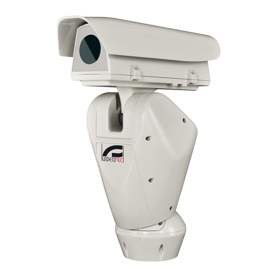
    4.1 Description et désignation du Les tourelles portent un étiquette conforme au marquage CE. produit ULISSE RADICAL THERMAL est le premier système PTZ thermique Videotec prêt à l'emploi qui intègre une combinaison exceptionnelle optique-caméra thermique ce qui permet une détection efficace des intrusions et la connaissance visuelle même...
  • Page 148: Préparation Du Produit En Vue De L'utilisation

    5 Préparation du produit en 5.3 Contenu vue de l’utilisation Contrôler que le contenu correspond à la liste matériel indiquée ci-dessous: Toute modification non approuvée • Unité de positionnement expressément par le fabricant entraînera • Base d'alimentation l’annulation de la garantie. •...
  • Page 149: Opérations À Effectuer Avant L'installation

    5.5 Opérations à effectuer avant 5.5.2 Passage des câbles l’installation Les câbles de connexion ne doivent pas être accessibles de l'extérieur. Les câbles 5.5.1 Fixation du support doivent être fixés au support pour éviter que le poids excessif n'entraîne leur sortie Plusieurs types de supports sont disponibles (9 accidentelle.
  • Page 150: Installation

    6 Installation 6.1 Connexion des câbles à la base Ne procéder sous aucun prétexte à des modifications ou des connexions non Passer les câbles dans les presse-câbles en prévues dans ce manuel. L’utilisation maintenant la base à environ 20cm du support. Serrer d’appareils inadéquats peut comporter les presse-étoupes.
  • Page 151: Fixage De La Base Au Support

    6.2 Fixage de la base au support 6.3 Description de la carte de connexion Utiliser les vis et les rondelles fournies avec la base. DESCRIPTION DE LA CARTE DE CONNEXION Connecteur/ Fonction Après avoir positionné le joint (01), fixer la base (02) Composant au support (03) en utilisant les vis (04), les rondelles à...
  • Page 152: Connexion De La Ligne D'alimentation

    6.4 Connexion de la ligne Le câble de terre doit être plus long des d'alimentation deux autres d'environ 10mm pour éviter tout détachement accidentel. Selon la version, différentes tensions d'alimentation peuvent être fournies au dispositif. La valeur de Le câble d'alimentation doit en outre être tension d'alimentation est reportée sur l'étiquette couvert de la gaine en silicone (01) fournie.
  • Page 153: Connexion De La Ligne D'alimentation En 24Vac

    6.4.1 Connexion de la ligne 6.4.2 Raccordement de la ligne d'alimentation en 24Vac d'alimentation en 120Vac et 230Vac Couper les câbles à la longueur nécessaire et Il faut, uniquement pour les produits procéder aux connexions. Connecter la ligne marqués UL alimentés à 24Vac, utiliser un d'alimentation avec la borne: CN1.
  • Page 154: Connexion Des Entrées D'alarme Et Des Relais

    6.4.3 Connexion des entrées d'alarme et Version avec projecteurs à LED des relais BRANCHEMENT DES ENTRÉES D'ALARME, DE L'INTERRUPTEUR CRÉPUSCULAIRE ET DES RELAIS ATTENTION! L'installation est du type TNV- AL1, AL2, AL3, Entrées d'alarme à alimentation automatique se 1. Ne pas la connecter à des circuits SELV. AL4 e ALARMS rapportant à...
  • Page 155: Branchement De La Ligne De Télémétrie

    6.7 Branchement de la ligne de 6.8 Fixation du corps supérieur télémétrie Fixer le corps supérieur (01) à la base (02) au moyen des vis de fixation (03) pourvues de joints (04). Ce chapitre s'applique aux modèles Contrôler que le joint de la base est en place et en analogiques du produit.
  • Page 156: Configuration Du Matériel

    OFF OFF OFF OFF ON DYNAMICS VISTA OFF OFF OFF ON OFF OFF ON Tab. 7 Configuration en ligne RS232: MACRO (VIDEOTEC), 115200 baud, Adresse 1. Cette option ne nécessite pas le réglage du DIP-switch (DIP1, DIP3). Fig. 24 MNVCUPKT_1838_FR...
  • Page 157: Configuration Du Dip3

    6.9.4 Configuration du DIP3 6.9.5 Configuration du DIP4 Le levier du switch vers le haut représente La configuration de ce DIP s'effectue à la valeur 1 (ON). Le levier du dip-switch vers l'inverse des DIP précédents. Le levier du le bas représente la valeur 0 (OFF). switch vers le haut représente la valeur 0 (OFF).
  • Page 158: Allumage

    7 Allumage Ne pas stationner à proximité du dispositif sous tension. N'intervenir sur le dispositif S'assurer que l'unité et les autres qu'avec l'alimentation coupée. composants de l'installation soient fermés de façon à empêcher le contact avec les La procédure de préchauffage automatique composants sous tension.
  • Page 159: Configuration

    8 Configuration 8.1.1.1 Utilisation du joystick Toutes les opérations des menus s'effectuent au Sur les modèles analogiques du produit, la moyen du manche à balai. configuration de la caméra advient à travers Haut OSM (8.1 Interface OSM (On Screen Menu), page 21).
  • Page 160: Comment Se Déplacer Dans Le Menu

    8.1.1.2 Comment se déplacer dans le menu 8.1.1.3 Comment modifier les paramètres Chaque page-écran du OSM présente une liste Se déplacer au moyen du curseur sur le paramètre de paramètres ou de sous-menus pouvant être à modifier et confirmer. Le champ commence à sélectionnés par l'opérateur.
  • Page 161: Comment Modifier Les Champs Numériques

    8.1.1.4 Comment modifier les champs 8.1.1.5 Comment modifier les textes numériques Se déplacer au moyen du curseur sur le paramètre à modifier et confirmer. Se déplacer au moyen du curseur sur le paramètre à modifier et confirmer. MODIFICATION ZONE ------------------------ MODIFIER PRESET 1 NR ------------------------...
  • Page 162 Il est possible d’utiliser le joystick pour naviguer à Utiliser: l’intérieur du menu. • EFFACE: Supprimer toute la chaîne de texte. • SAUVE: Sauvegarder le nouveau texte avant de EDIT TEXT: AREA quitter le menu. ------------------------ • SORTIE: Quitter le menu. Text: TEXT AREA1 ↑...
  • Page 163: Configuration Par Osm

    8.1.2 Configuration par OSM 8.1.5 Menu Paramètres ZFI Les pages-écrans qui servent à configurer le produit Zoom: Programme le nombre maximum sont illustrées ci-après. d'agrandissements que peut effectuer l'optique motorisée. 8.1.3 Menu Principal Fil Commun: Si validé, il gère les optiques Le menu principal permet d'accéder à...
  • Page 164: Menu Titrage Des Zones

    8.1.5.1 Menu Titrage Des Zones Exemple: Pour activer le titrage de la zone 1 quand le dispositif se trouve entre +15° et +45°, procéder Cette fonction permet de configurer un maximum comme suit: de huit zones (de dimensions variables) et •...
  • Page 165: Menu Masquage Des Zones

    8.1.5.2 Menu Masquage des Zones Exemple: Pour activer le masquage de la zone 1 quand le dispositif se trouve entre +15° et +45° il faut: Cette fonction permet de configurer un maximum • Sélectionner 1 comme valeur du paramètre N° de huit masques (de dimensions variables) et éventuellement de les titrer.
  • Page 166: Menu Communication Sérielle Caisson

    8.1.6 Menu Communication Sérielle 8.1.7 Menu Polarité Caisson Il permet de configurer les paramètres suivants : Zoom: Il permet de choisir la polarité de rotation Après être sorti du OSM de la caméra, du moteur du Zoom de l'optique. appuyer sur la touche Iris Close pour retourner au menu OSM de la tourelle.
  • Page 167: Menu Mouvement

    8.1.8 Menu Mouvement 8.1.8.1 Menu Contrôle Manuel Vitesse Maximale: Configuration de la vitesse Offset Pan: La tourelle a une position de 0° manuelle maximale. définie mécaniquement. La fonction Offset Pan permet de définir une position différente de 0° à Vitesse avec Zoom: L’activation de ce l’aide du logiciel.
  • Page 168: Menu Contrôle Manuel (Limites)

    8.1.8.2 Menu Contrôle Manuel (Limites) 8.1.8.4 Menu Preset (Modifier Preset) Il permet de configurer les paramètres suivants : Il permet de configurer les paramètres suivants : Limites Pan: Valide les limites de Pan. Numéro: Numéro du Preset devant être modifié. Pan Début: Configure la limite initiale de Pan.
  • Page 169: Menu Preset (Utilités Preset)

    8.1.8.5 Menu Preset (Utilités Preset) 8.1.8.6 Menu Patrol Il permet de configurer les paramètres suivants : Premier Preset: Premier preset de la séquence de Patrol. Vitesse Scan: Vitesse utilisée pour atteindre la position de Preset en cas de rappel avec la Dernier Preset: Le dernier Preset de la séquence commande Scan.
  • Page 170: Menu Rappel Mouvements

    8.1.8.8 Menu Rappel Mouvements Commandes Reçues: Permet de valider l'affichage des commandes sérielles reçues. Il est possible de configurer le dispositif de façon Delta Horizontal: Déplacement horizontal des à ce que, après une certaine période d'inactivité, textes des menus afin de permettre un meilleur il effectue automatiquement une fonction de centrage.
  • Page 171: Menu Alarmes

    8.1.10.1 Menu Alarmes Le menu se configure automatiquement de façon dynamique en fonction de la sélection effectuée en 01-04. Alarmes 1-4: Accès aux menus dans affichant les paramètres pouvant être modifiés. lesquels il est possible de modifier les Le menu État des Alarmes affiche l'état des entrées paramètres des Alarmes de 1 à...
  • Page 172: Menu Par Défaut

    8.1.11 Menu Par Défaut 8.1.12 Menu Infos Effacer Setup?: Rétablissement de tous les Permet de vérifier la configuration du dispositif et la paramètres à l’exception des preset. version de micrologiciel installée. Effacer Preset?: Élimine tous les preset mémorisés précédemment. REMARQUE ------------------------ Device ID: 00001 DEFAULT...
  • Page 173: Menu Caméra Thermique

    8.1.13 Menu Caméra Thermique Pour activer les configurations avancées, Langue: Le menu permet de choisir la langue sélectionner le poste Custom. désirée. Flat Field Correction: Permet d'accéder au État: Permet d'accéder au sous-menu où sont sous-menu pour la configuration de la Flat Field reportées les informations techniques de la Correction (FFC) et du Gain Mode.
  • Page 174: Menu Status

    8.1.13.1 Menu Status 8.1.13.3 Menu Configuration vidéo Fournit les informations sur la caméra thermique Pour les produits IP, ne pas modifier installée. Affiche la température interne de la caméra. le format vidéo de NTSC à PAL. La Les 4 premières valeurs sont exprimées en format modification de cette programmation hexadécimal.
  • Page 175: Menu Correction Flat Field

    8.1.13.4 Menu Correction Flat Field Mode Gain: Permet de sélectionner le type de plage dynamique de gain: La caméra thermique possède un mécanisme • High: Cette configuration est prévue pour interne permettant d’améliorer périodiquement la optimiser le contraste et particulièrement qualité...
  • Page 176: Valeurs Modification Gain

    8.1.13.5 Valeurs Modification Gain 8.1.13.6 Menu Digital Data Enhancement Il permet de configurer les paramètres suivants : Ce menu permet de configurer l'algorithme Digital Data Enhancement (DDE). Seuil High-Low: Configure le seuil de température utilisé par le paramètre Mode DDE: L'algorithme DDE peut être utilisé Pourcentage High-Low pour forcer la pour améliorer les détails de l'image et/ou commutation en mode Low Gain.
  • Page 177: Menu Automatic Gain Correction (Agc)

    8.1.13.7 Menu Automatic Gain Correction Manual: L'algorithme DDE est configuré manuellement au moyen de 3 paramètres. (AGC) DDE Gain: Représente le gain à haute Il permet de configurer les paramètres suivants : fréquence. Avec la valeur à 0, la DDE est exclue. Type AGC: À...
  • Page 178: Menu Configuration Roi

    8.1.13.8 Menu Configuration ROI Configuration ROI: Region Of Interest (ROI) pour l’algorithme AGC. Une fois entré dans le menu Configuration ROI, il est Paramètres Plateau: Permet d'accéder à la liste possible de modifier la région intéressée (ROI) utilisée des paramètres pouvant être configurés pour la par l’algorithme AGC pour calculer les niveaux de modalité...
  • Page 179: Menu Paramètres Agc Plateau

    8.1.13.9 Menu Paramètres AGC Plateau 8.1.13.10 Menu Paramètres AGC Linear Paramètres relatifs à la modalité AGC : Plateau Paramètres relatifs à la modalité AGC : Linear. equalization. Il permet de configurer les paramètres suivants : Il permet de configurer les paramètres suivants : ITT Midpoint: Configure le point moyen de Plateau Value: Programme la valeur maximale l’échelle de gris.
  • Page 180: Menu Paramètres Agc Manual

    8.1.13.11 Menu Paramètres AGC Manual 8.1.13.12 Menu Paramètres AGC Auto Bright Paramètres relatifs à la modalité AGC : Manual. Paramètres relatifs à la modalité AGC : Auto Bright. Il permet de configurer les paramètres suivants : Il permet de configurer les paramètres suivants : Luminosité: Configure le point moyen de Contraste: Programme le niveau de contraste l’échelle de gris.
  • Page 181: Menu Paramètres Agc Once Bright

    8.1.13.13 Menu Paramètres AGC Once Bright 8.1.13.15 Menu Isotherm Paramètres relatifs à la modalité AGC : Once Bright. Dans le menu Isotherm, il est possible d'activer une coloration spéciale pour des objets compris dans Il permet de configurer les paramètres suivants : l’intervalle de température programmé.
  • Page 182: Interface Web

    8.2 Interface web 8.2.1 Page Home Si le login est effectué avec succès, on pourra voir L’appareil est configuré pour obtenir l'interface de gestion de le produit. l’adresse IP depuis un serveur DHCP. Logiciels de navigation supportés: Microsoft Internet Explorer, Google Chrome, Mozilla Firefox.
  • Page 183: Page Contrôles Utilisateur

    8.2.2 Page Contrôles Utilisateur • Iris close/Iris open/Auto iris Pour contrôler la dispositif par browser, sélectionner la mention Contrôle Utilisateur. Une nouvelle fenêtre s'ouvrira, avec un clavier virtuel pour sélectionner les commandes. Fig. 88 • OSM ON: Active l'On Screen Menu (OSM) qui permet la configuration de la caméra thermique.
  • Page 184: Page Paramètres Dispositif

    8.2.3 Page Paramètres Dispositif 8.2.5 Page Configuration Réseau A la mention du menu Paramètres Dispositif il est A la mention du menu Réseau il est possible de possible de configurer le nom de le dispositif et changer la configuration de réseau de la tourelle. Il d'afficher d'autres informations supplementaire.
  • Page 185: Page Configuration Utilisateurs

    8.2.7 Page Paramètres Mouvement Serveur NTP: Il est également possible de mentionner si le dispositif doit se synchroniser avec A la mention du menu Paramètres Mouvement il est un serveur NTP (Network Time Protocol) externe. possible de contrôler par web tous les paramètres de •...
  • Page 186: Page Autopan

    8.2.7.1 Page Autopan 8.2.8 Page Paramètres Preset A la mention du menu Autopan il est possible A la mention du menu Paramètres Preset on peut d'indiquer le preset de début et de fin de l'autopan. configurer certains paramètres concernant les preset: •...
  • Page 187: Page I/O Digitaux

    8.2.10 Page I/O Digitaux • WIPER: Activer le Wiper. • WASHER: Activer la séquence de lavage de la Dans la carte I/O Digitaux il est possible de configurer vitre. les canaux digitaux présents dans le dispositif. Il y a ci-dessous une courte description des paramètres •...
  • Page 188: Page Paramètres Caméra

    8.2.11 Page Paramètres Caméra 8.2.12 Page Instruments Les paramètres de la caméra IP qui ont été configurés A la mention du menu Instruments il est possible à la première mise en marche sont modifiables de reconfigurer les valeurs prédéfinies pour toute dans la section Paramètres Caméra.
  • Page 189: Factory Default

    9 Accessoires 8.2.14 Factory Default Si le mot de passe ne est plus disponible, Pour de plus amples informations sur la il est possible de rétablir les paramétrages configuration et l'utilisation, consulter le d’usine à l’aide de la touche reset, situé à manuel de l'accessoire correspondant.
  • Page 190: Instructions De Fonctionnement Courant

    10 Instructions de 10.2 Enregistrement d'un Preset fonctionnement courant A l'aide du dispositif de contrôle utilisé, il est possible de sauvegarder la position actuelle (pour de plus 10.1 Affichage de l’état de la amples informations, se référer au manuel du dispositif utilisé).
  • Page 191: Activation De L'autopan

    10.6 Activation de l'Autopan 10.7 Reboot du dispositif La fonction Autopan rappelle de façon continue les 2 Au moyens d'un dispositif de contrôle il est possible Preset mémorisés. d'envoyer la commande de réinitialisation de l'unité (pour plus d’informations, se référer au manuel du Pour activer/désactiver la fonction se référer au dispositif de contrôle utilisé).
  • Page 192: Commandes Spéciales

    10.8 Commandes spéciales COMMANDES SPÉCIALES Action Commande Protocole AMERICAN ERNITEC PANASONIC PELCO D VIDEOTEC VISTA DYNAMICS MACRO Exécuter Sauver Preset 74 Sauver Preset 74 Sauver Preset 74 Sauver Preset 74 Sauver Preset 74 Sauver Preset 43 Autofocus Sauver Preset 83...
  • Page 193: Configuration Spéciales

    10.9 Configuration spéciales CONFIGURATION SPÉCIALES Configuration Protocole AMERICAN DYNA- PANASONIC PELCO D VIDEOTEC MACRO VISTA MICS Washer Configura- Sauver Preset 72 Sauver Preset 72 Sauver Preset 72 Sauver Preset 72 Sauver Preset 72 tion 1 (lavage court) Washer Configura- Sauver Preset 73...
  • Page 194: Entretien

    11 Entretien 12 Nettoyage 12.1 Entretiens de la vitre et des L’entretien doit être uniquement effectué par un personnel qualifié en matière de parties en plastique circuits électriques. On doit éviter alcool éthylique, solvants, 11.1 Remplacement des fusibles hydrocarbures hydro-génés, acides forts et alcali.
  • Page 195: Dépannage

    14 Dépannage PROBLÈME Durant la mise en service, la tourelle reste bloquée. CAUSE La température ambiante est Pour toute problématique non décrite ou si très basse. les problèmes énumérés ci-après persistent, contactez le centre d'assistance agréé. SOLUTION Attendre la fin de la procédure de préchauffage.
  • Page 196: Données Techniques

    15 Données techniques 15.4 Optiques Zoom optique 3x, 35-105mm, F1.6 15.1 Généralités Distance minimale de mise au point: 7m Fabriqué en fonte d’aluminium et en technopolymère Angle de vision (640x512 pixel): Vernissage avec poudres époxypolyester, couleur • Wide: 17.97°H, 14.33°V RAL9002 •...
  • Page 197: Réseau

    15.7 Réseau 15.10 Certifications Connecteur: RJ45, 10BASE-T/100BASE-T Sécurité électrique (CE): EN60950-1, IEC60950-1 Compatibilité électromagnétique (CE): EN50130- 15.8 Protocoles réseau 4, EN610000-6-4, EN55022 (Classe A), FCC Part 15 (Classe A) Protocole: ONVIF, Profil S Installation à l'extérieur (CE): EN60950-22, IEC60950- Configuration du dispositif: TCP/IPv4, UDP/IPv4, HTTP, NTP, DHCP, WS-DISCOVERY, QoS Degré...
  • Page 198: Dessins Techniques

    16 Dessins techniques Les dimensions des dessins sont exprimées en millimètres. Ø 66 Fig. 109 ULISSE RADICAL THERMAL MNVCUPKT_1838_FR...
  • Page 199: A Annexe - Tableau Des Adresses

    A Annexe - Tableau des adresses Le levier du switch vers le haut représente la valeur 1 (ON). Le levier du dip-switch vers le bas représente la valeur 0 (OFF). Ci-après, on reporte toutes les combinaisons possibles. CONFIGURATION DE L'ADRESSE (DIP 3) SW 8 SW 7 SW 6...
  • Page 200 CONFIGURATION DE L'ADRESSE (DIP 3) SW 8 SW 7 SW 6 SW 5 SW 4 SW 3 SW 2 SW 1 Adresse Adresse 39 Adresse 40 Adresse 41 Adresse 42 Adresse 43 Adresse 44 Adresse 45 Adresse 46 Adresse 47 Adresse 48 Adresse 49 Adresse 50...
  • Page 201 CONFIGURATION DE L'ADRESSE (DIP 3) SW 8 SW 7 SW 6 SW 5 SW 4 SW 3 SW 2 SW 1 Adresse Adresse 83 Adresse 84 Adresse 85 Adresse 86 Adresse 87 Adresse 88 Adresse 89 Adresse 90 Adresse 91 Adresse 92 Adresse 93 Adresse 94...
  • Page 202 CONFIGURATION DE L'ADRESSE (DIP 3) SW 8 SW 7 SW 6 SW 5 SW 4 SW 3 SW 2 SW 1 Adresse Adresse 127 Adresse 128 Adresse 129 Adresse 130 Adresse 131 Adresse 132 Adresse 133 Adresse 134 Adresse 135 Adresse 136 Adresse 137 Adresse 138...
  • Page 203 CONFIGURATION DE L'ADRESSE (DIP 3) SW 8 SW 7 SW 6 SW 5 SW 4 SW 3 SW 2 SW 1 Adresse Adresse 171 Adresse 172 Adresse 173 Adresse 174 Adresse 175 Adresse 176 Adresse 177 Adresse 178 Adresse 179 Adresse 180 Adresse 181 Adresse 182...
  • Page 204 CONFIGURATION DE L'ADRESSE (DIP 3) SW 8 SW 7 SW 6 SW 5 SW 4 SW 3 SW 2 SW 1 Adresse Adresse 215 Adresse 216 Adresse 217 Adresse 218 Adresse 219 Adresse 220 Adresse 221 Adresse 222 Adresse 223 Adresse 224 Adresse 225 Adresse 226...
  • Page 205 MNVCUPKT_1838_FR...
  • Page 206 Email: info@videotec.com Tel. +33 1 60491816 - Fax +33 1 69284736 Email: info.fr@videotec.com Asia Pacific Videotec (HK) Ltd Americas Videotec Security, Inc. Flat 8, 19/F. On Dak Industrial Building, No. 2-6 Wah Sing Street Gateway Industrial Park, 35 Gateway Drive, Suite 100 Kwai Chung, New Territories - Hong Kong Plattsburgh, NY 12901 - U.S.A.
  • Page 207 DEUTSCH ULISSE RADICAL THERMAL Wärmebildkamera PTZ mit stufenlosem 24-fachem Zoom Deutsch - Bedienungsanleitung...
  • Page 209 Inhaltsverzeichnis D E U T S C H 1 Allgemeines ..........................6 1.1 Schreibweisen..................................6 2 Anmerkungen zum Copyright und Informationen zu den Handelsmarken ......6 3 Sicherheitsnormen ........................6 4 Identifizierung .......................... 9 4.1 Beschreibung und Bezeichnung des Produktes ......................9 4.2 Kennzeichnung des Produkts ............................
  • Page 210 8.1.1.3 Ändern von Parametern ......................................22 8.1.1.4 Ändern der Zahlenfelder ......................................23 8.1.1.5 Ändern von Texten ........................................23 8.1.2 Konfiguration über OSM ..................................25 8.1.3 Hauptmenü ......................................25 8.1.4 Menü Sprachwahl ....................................25 8.1.5 Menü Parameter ZFI .....................................25 8.1.5.1 Menü Zonenbetitelung ......................................26 8.1.5.2 Menü...
  • Page 211 8.2.8 Preset-Parameter Seite ..................................48 8.2.9 Preset-Parameter Seite (Fortgeschritten) ............................48 8.2.10 Digitale I/O Seite ....................................49 8.2.11 Kamera-Parameter Seite ...................................50 8.2.12 Werkzeuge Seite ....................................50 8.2.13 Menü Thermische Videokamera ..............................50 8.2.14 Factory Default .....................................51 9 Zubehör ...........................51 9.1 Wandhalterung ..................................51 9.2 Halterung für Brüstungsmontage ..........................51 10 Anleitung für den normalen Betrieb ..................52 10.1 Statusanzeige Schwenk-Neige-Kopf ...........................52 10.2 Speichern eines Preset.
  • Page 212: Allgemeines

    1 Allgemeines 3 Sicherheitsnormen Vor Installation und Anwendung der Einheit ist die ACHTUNG! Die elektrische Anlage, an gesamte gelieferte Dokumentation aufmerksam zu der die Einheit angeschlossen ist, muss lesen. Zum späteren Nachschlagen das Handbuch in mit einem automatischen zweipoligen Reichweite aufbewahren. Schutzschalter 20A max ausgestattet sein.
  • Page 213 • Unterbrechen Sie die Stromversorgung, bevor die • Die Einrichtung ist für die dauerhafte Befestigung beschriebenen Arbeiten durchgeführt werden. und Verbindung in ein Gebäude oder eine andere geeignete Struktur konzipiert. Vor jeder Operation • Es dürfen keine Kabel mit Verschleiß- oder muss die Einrichtung dauerhaft befestigt und Alterungsspuren verwendet werden.
  • Page 214 • Kindern oder unbefugten Personen ist der • Vermeiden Sie durch gebotene Vorkehrungen, Gebrauch des Gerätes zu untersagen. dass das Gerät durch elektrostatische Entladungen beschädigt wird. • Die Wartung der Einrichtung ist Fachleuten vorbehalten. Während der Wartungsarbeiten ist die • Die Einheit ist dafür ausgelegt, über ein dreipoliges tätige Person der Gefahr von Stromschlägen und Kabel angeschlossen zu werden.
  • Page 215: Identifizierung

    Auf den Schwenk-Neige-Köpfen befindet sich ein Schildchen, das der CE- Bezeichnung des Produktes Kennzeichnung entspricht. ULISSE RADICAL THERMAL ist das erste gebrauchsfertige thermische PTZ-System von Videotec. Er stellt eine hervorragende Kombination zwischen Optik und Wärmebildkamera dar und gewährleistet eine effiziente Erfassung von Eindringlingen sowie das visuelle Bewusstsein auch bei völliger Dunkelheit oder unter extremen...
  • Page 216: Vorbereitung Des Produktes Auf Den Gebrauch

    5 Vorbereitung des 5.3 Inhalt Produktes auf den Gebrauch Prüfen Sie, ob der Inhalt mit der nachstehenden Materialliste übereinstimmt: Jede vom Hersteller nicht ausdrücklich • Positionierungseinheit genehmigte Veränderung führt zum Verfall • Basis für Netzstromversorgung der Gewährleistungsrechte. • Zubehör Packung: •...
  • Page 217: Auf Die Installation Vorbereitende Tätigkeiten

    5.5 Auf die Installation 5.5.2 Kabelführung vorbereitende Tätigkeiten Die Verbindungskabel dürfen von außen nicht zugänglich sein. Die Kabel mussen 5.5.1 Befestigung der Halterung gegen Lösen durch Abziehen sachgerecht am Träger fixiert werden, damit es Verschiedene Halterungen sind (9 Zubehör, Seite 51). verhindert wird, dass es durch das hohe Das geeignetste für die Installation auswählen und Gewicht unbeabsichtigt abgezogen wird.
  • Page 218: Installation

    6 Installation 6.1 Anschließen der Kabel an die Basis Unter keinen Umständen dürfen Veränderungen oder Anschlüsse Die Kabel in den Kabelschellen einführen, während vorgenommen werden, die in diesem die Basis etwa 20cm von der Halterung entfernt Handbuch nicht genannt sind. Die gehalten wird.
  • Page 219: Befestigung Der Basis An Der Halterung

    6.2 Befestigung der Basis an der 6.3 Beschreibung der Karte Halterung Anschlüsse BESCHREIBUNG DER KARTE ANSCHLÜSSE Verwenden Sie die mit der Basis gelieferten Schrauben und Unterlegscheiben. Verbinder/ Funktion Komponente Nach der Positionierung der Dichtung (01), die Basis Platinenversorgung (02) mit den Schrauben (04), den Zahnscheiben (05) Signalkabel und den Ringen für Schrauben (06) an der Halterung Ethernet...
  • Page 220: Anschluss Der Stromversorgung

    6.4 Anschluss der Das Erdungskabel muss um etwa 10mm Stromversorgung länger sein, als die anderen beiden Kabel, um das ungewollte Lösen durch Ziehen des Je nach Version kann die Vorrichtung mit Kabels zu verhindern. unterschiedlichen Versorgungsspannungen geliefert werden. Der Wert der Versorgungsspannung ist Ferner muss das Versorgungskabel von auf dem Kenndatenschildchen des Produktes einer Silikonummantelung (01) überzogen...
  • Page 221: Anschluss Der Stromversorgunglinie 24Vac

    6.4.1 Anschluss der 6.4.2 Anschluss der Versorgungsleitung Stromversorgunglinie 24Vac in 120Vac und 230Vac Die Kabel zuschneiden und die unten beschriebenen Lediglich für die Produkte mit UL - Anschlüsse vornehmen. Die Versorgungsleitung am Markierung mit 24Vac - Versorgung ein Klemmen anschließen: CN1. UL - Speisetransformator der Klasse 2 verwenden, welches den geltenden Richtlinien entspricht.
  • Page 222: Anschluss Der Alarmeingänge Und Der Relais

    6.4.3 Anschluss der Alarmeingänge und Version mit LED- Scheinwerfern der Relais. ANSCHLUSS DER ALARMEINGÄNGE, DER DÄMMERUNGSSCHALTER UND DER RELAIS ACHTUNG! Die Anlage gehört zum Typ TNV- AL1, AL2, AL3, Eigenbetriebene Alarmeingänge in Bezug auf 1. Nicht an Kreisläufe SELV anschließen. AL4 e ALARMS die gemeinsame Klemme ALARMS O1-C1 e O2-C2 Potentialfreie Ausgangskontakte, die durch...
  • Page 223: Anschluss Der Telemetrieleitung

    6.7 Anschluss der 6.8 Befestigung des oberen Telemetrieleitung Körpers Den oberen Körper (01) mit den Spannschrauben (03) Dieses Kapitel gilt für die analogen und Dichtungen (04) an der Basis (02) befestigen. Produktmodelle. Prüfen Sie, ob die Dichtung (05) der Basis vorhanden und in einwandfreiem Zustand ist.
  • Page 224: Hardware Konfiguration

    OFF OFF ON AMERICAN OFF OFF OFF OFF ON DYNAMICS VISTA OFF OFF OFF ON OFF OFF ON Tab. 7 Konfiguration Leitung RS232: MACRO (VIDEOTEC), Abb. 24 115200 baud, Adresse 1. Diese Option benöigt keine Einstellung der DIP-switch (DIP1, DIP3). MNVCUPKT_1838_DE...
  • Page 225: Konfiguration Von Dip3

    6.9.4 Konfiguration von DIP3 6.9.5 Konfiguration von DIP4 Der nach oben zeigende Kipphebel des Die Einstellung dieses Dipschalters Schalters steht für den Wert 1 (ON). Der erfolgt in umgekehrter Reihenfolge wie nach unten zeigende Kipphebel des die vorherige. Der nach oben zeigende Dipschalters steht für den Wert 0 (OFF).
  • Page 226: Einschaltung

    7 Einschaltung Vergewissern Sie sich, dass alle Teile fest und zuverlässig befestigt sind. Sicherstellen, das die Einheit und die anderen Bauteile der Anlage korrekt Der automatische Vorheizvorgang (De-Ice) geschlossen sind, um den Kontakt mit könnte immer dann aktiviert werden, wenn unter Spannung stehenden Bauteilen zu das Gerät bei einer Umgebungstemperatur verhindern.
  • Page 227: Konfiguration

    8 Konfiguration 8.1.1.1 Verwendung des Steuerknüppels Alle Menüvorgänge werden mit dem Steuerknüppel Bei den analogen Produktmodellen erfolgt veranlasst. die Kamerakonfiguration über OSM (8.1 OSM-Schnittstelle (On Screen Menu), Seite  21). Bei den IP-Modellen des Produktes erfolgt die Kamerakonfiguration über die Webseite (8.2 Web-Schnittstelle, Seite 44). Links Rechts 8.1 OSM-Schnittstelle (On Screen...
  • Page 228: Das Bewegen Innerhalb Der Menüs

    8.1.1.2 Das Bewegen innerhalb der Menüs 8.1.1.3 Ändern von Parametern Jeder OSM-Bildschirm weist eine Liste mit Parametern Den Cursor auf den zu ändernden Parameter oder Untermenüs auf, die vom Bediener angewählt bewegen und bestätigen. Das Feld beginnt zu werden können. Um die verschiedenen Parameter blinken als Zeichen dafür, dass es geändert wird.
  • Page 229: Ändern Der Zahlenfelder

    8.1.1.4 Ändern der Zahlenfelder 8.1.1.5 Ändern von Texten Den Cursor auf den zu ändernden Parameter Den Cursor auf den zu ändernden Parameter bewegen und bestätigen. bewegen und bestätigen. PRESET ANDERN ZONE ANDERN ------------------------ ------------------------ 1 NR. 1 NR 2 ENAB.: 2 START:+ 0.00 3>PAN...
  • Page 230 Es ist möglich, mit dem Joystick innerhalb des Menüs Verwenden Sie: zu navigieren. • LOESCHT: Die gesamte Textzeichenfolge löschen. • SPEICHERN: Speichern des neuen Textes vor dem EDIT TEXT: AREA Austritt aus dem Menü. ------------------------ • AUSGANG: Austritt aus dem Menü. Text: TEXT AREA1 ↑...
  • Page 231: Konfiguration Über Osm

    8.1.2 Konfiguration über OSM 8.1.5 Menü Parameter ZFI Im Folgenden werden die Bildschirmseiten zur Zoom: Einstellbar ist die maximale Konfiguration des Produkts beschrieben. Vergrößerungszahl, welche die motorisierte Optik leisten kann. 8.1.3 Hauptmenü Gemeinsamer Draht: Wird diese Option Vom Hauptmenü aus kann die Konfigurierung der aktiviert, werden die motorisierten Optiken mit Einrichtung aufgerufen werden.
  • Page 232: Menü Zonenbetitelung

    8.1.5.1 Menü Zonenbetitelung Beispiel: Um die Betitelung der Zone 1 zu aktivieren, wenn sich die Vorrichtung zwischen +15° und +45° Diese Funktion gestattet die Festlegung von bis zu befindet, ist folgendermaßen vorzugehen: acht Zonen (verschiedener Größe), die sich betiteln • Die Zonenbetitelung aktivieren, indem man lassen.
  • Page 233: Menü Zonenmaskierung

    8.1.5.2 Menü Zonenmaskierung Beispiel: Zur Aktivierung der Maskierung von Zone 1wenn sich die Vorrichtung zwischen +15° und +45° Diese Funktion gestattet die Festlegung von bis zu befindet wie folgt vorgehen: acht Masken (verschiedener Größe), die sich betiteln • Auswahl von 1 als Wert des Parameters Nr. lassen.
  • Page 234: Menü Gehäuse Seriell

    8.1.6 Menü Gehäuse seriell 8.1.7 Menü Polarität Ermöglicht die Konfiguration folgender Parameter: Nachdem das OSM der Kamera verlassen Zoom: Ermöglicht die Auswahl der Polarität der worden ist, die Taste Iris Close drücken, Motordrehung des Zooms der Optik. um zum OSM des Schwenk-Neige-Kopfes zurückzukehren.
  • Page 235: Menü Bewegung

    8.1.8 Menü Bewegung 8.1.8.1 Menü Handsteuerung Höchstgeschwindigkeit: Auswahl der Offset Pan: Der Schwenk-Neige-Kopf hat eine maximalen manuellen Geschwindigkeit. Position von 0°, die mechanisch definiert ist. Die Funktion Offset Pan ermöglicht es, auf Geschwindigkeit Mit Zoom: Bei Aktivierung Softwareebene eine andere Position als 0° dieses Parameters wird die Geschwindigkeit für festzulegen.
  • Page 236: Menü Handsteuerung (Grenzpunkte)

    8.1.8.2 Menü Handsteuerung (Grenzpunkte) 8.1.8.4 Menü Preset (Preset Ändern) Ermöglicht die Konfiguration folgender Parameter: Ermöglicht die Konfiguration folgender Parameter: Grenzpunkte Pan: Aktiviert die Grenzpunkte für Nummer: Dies ist die Nummer des zu die Funktion Pan (Kameraschwenk). ändernden Preset. Beginn Pan: Vorgabe der Grenzposition zu Befähigung: Zum Einschalten des Preset.
  • Page 237: Menü Preset (Utility Preset)

    8.1.8.5 Menü Preset (Utility Preset) 8.1.8.6 Menü Patrol Ermöglicht die Konfiguration folgender Parameter: Erstes Preset: Erster Preset der Sequenz Patrol. Scan Geschwindigkeit: Geschwindigkeit, die Letzes Preset: Letzter Preset der Sequenz Patrol. dazu verwendet wird, um die Preset-Position Random Modus: Aktiviert wird die zufällige nach dem Empfang eines Befehls Scan zu Ausführung.
  • Page 238: Menü Bewegungsanforderung

    8.1.8.8 Menü Bewegungsanforderung Empfangene Befehle: Es wird die Funktion aktiviert, mit der die empfangenen seriellen Das Gerät kann so konfiguriert werden, dass nach Befehle angezeigt werden. einer gewissen Zeit der Inaktivität automatisch eine Delta Horizontal: Horizontale Verstellung der vom Bediener ausgewählte Bewegungsfunktion Menütexte für eine bessere Zentrierung.
  • Page 239: Menü Alarme

    8.1.10.1 Menü Alarme Das Menü konfiguriert sich dynamisch in Abhängigkeit von der gewählten Einstellung und 01-04. Alarme 1-4: Zugriff auf die Menüs, in weist die Parameter aus, die verändert werden denen die Parameter der Alarme von 1 bis 4 können. geändert werden können.
  • Page 240: Menü Default

    8.1.11 Menü Default 8.1.12 Menü Info Setup löschen?: Versetzt alle Parameter außer Das Menü ermöglicht es, die Konfiguration der die Presetparameter in den ursprünglichen Einrichtung und die Version der installierten Firmware Zustand. zu prüfen. Preset löschen?: Löscht alle gespeicherten ANMERKUNG Presetpositionen.
  • Page 241: Menü Thermische Videokamera

    8.1.13 Menü Thermische Videokamera Um die fortgeschrittenen Konfigurationen Sprache: Mit dem Menü kann die gewünschte zu aktivieren, wählen Sie bitte den Sprache ausgewählt werden. Menüpunkt Custom. Status: Ermöglicht den Zugang zu dem Flat Field Correction: Aufrufbar ist das Untermenü, in dem die technischen Untermenü...
  • Page 242: Menü Status

    8.1.13.1 Menü Status 8.1.13.3 Menü Videokonfiguration Enthält Angaben zur installierten thermischen Bei den IP-Produkten darf das Videoformat Videokamera. Stellt die Innentemperatur der nicht von NTSC zu PAL geändert werden. Videokamera dar. Die ersten 4 Werte sind im Bei einer Änderung dieser Einstellung wird Hexadezimal-Format angegeben.
  • Page 243: Menü Flat-Field-Korrektur

    8.1.13.4 Menü Flat-Field-Korrektur Verstärkungsmodus: Hier kann die Art des dynamischen Verstärkungsbereiches gewählt Die Wärmebildkamera hat einen internen werden: Mechanismus, der in bestimmten Zeitabständen die • High: Diese Einstellung ist dazu bestimmt, Bildqualität verbessert: Die Flat-Field-Korrektur (FFC). den Kontrast zu maximieren. Besonders Die Funktionsparameter sind die Folgenden: geeignet ist sie für Anwendungen mit FFC ausführen: Veranlasst wird ein FFC-...
  • Page 244: Werte Verstärkungskontrolle Schalt

    8.1.13.5 Werte Verstärkungskontrolle Schalt 8.1.13.6 Menü Digital Data Enhancement Ermöglicht die Konfiguration folgender Parameter: Dieses Menü erlaubt die Konfiguration des Algorithmus Digital Data Enhancement (DDE). Schwelle High-Low: Für die Einstellung der Temperaturschwelle, auf die der Prozentsatz Modus DEE: Der Algorithmus DDE kann zur High-Low Parameter zurückgreift, um in den Verbesserung der Bilddetails und/oder zur Modus Low Gain umzuschalten.
  • Page 245: Menù Automatic Gain Correction (Agc)

    8.1.13.7 Menù Automatic Gain Correction Manual: Der Algorithmus DDE wird manuell anhand von 3 Parametern eingestellt. (AGC) DDE Gain: Dies ist die Ermöglicht die Konfiguration folgender Parameter: Hochfrequenzverstärkung. Bei einem Wert von 0 Typ AGC: Im Menü kann die automatische ist DDE deaktiviert.
  • Page 246: Menü Konfiguration Roi

    8.1.13.8 Menü Konfiguration ROI Konfiguration ROI: Region Of Interest (ROI) für den Algorithmus AGC ein. Nach dem Aufruf des Menüs Konfiguration ROI kann Parameter Plateau: Aufrufbar ist die Liste der Bereich, der von Interesse ist (region of interest der Parameter, die für den Modus Plateau - ROI) geändert werden, der vom Algorithmus AGC konfigurierbar sind.
  • Page 247: Menü Parameter Agc Plateau

    8.1.13.9 Menü Parameter AGC Plateau 8.1.13.10 Menü Parameter AGC Linear Parameter des Modus AGC: Plateau equalization. Parameter des Modus AGC: Linear. Ermöglicht die Konfiguration folgender Parameter: Ermöglicht die Konfiguration folgender Parameter: Plateau Value: Einstellung des Höchstwertes ITT Midpoint: Eingestellt wird der für die Pixelzahl, die in einem Grauton enthalten Durchschnittspunkt der Grauskala.
  • Page 248: Menü Parameter Agc Manual

    8.1.13.11 Menü Parameter AGC Manual 8.1.13.12 Menü Parameter AGC Auto Bright Parameter des Modus AGC: Manual. Parameter des Modus AGC: Auto Bright. Ermöglicht die Konfiguration folgender Parameter: Ermöglicht die Konfiguration folgender Parameter: Helligkeit: Eingestellt wird der Kontrast: Eingestellt wird der Kontrastgrad des Durchschnittspunkt der Grauskala.
  • Page 249: Menü Parameter Agc Once Bright

    8.1.13.13 Menü Parameter AGC Once Bright 8.1.13.15 Menü Isotherm Parameter des Modus AGC: Once Bright. Im Menü Isotherm lässt sich eine spezielle Kolorierung für Objekte aktivieren, die innerhalb des Ermöglicht die Konfiguration folgender Parameter: vorgegebenen Temperaturbereichs liegen. Brightness Bias: Einstellung des Ermöglicht die Konfiguration folgender Parameter: Helligkeitsabgleichs.
  • Page 250: Web-Schnittstelle

    8.2 Web-Schnittstelle 8.2.1 Home Seite Wenn der Login erfolgreich abgeschlossen wurde, Die Einheit ist konfiguriert, um eine wird die Steuer-Schnittstelle des Produktes angezeigt. IP-Adresse von einem DHCP-Server zu erhalten. Unterstützte Browser: Microsoft Internet Explorer, Google Chrome, Mozilla Firefox. Die MAC Address wird auf dem Etikett an der CPU-Karte angegeben.
  • Page 251: Benutzersteuerung Seite

    8.2.2 Benutzersteuerung Seite • Iris close/Iris open/Auto iris Um die Einrichtung via Browser zu steuern, wählen Sie den Eintrag Benutzersteuerung. Es öffnet sich ein neues Fenster mit einer virtuellen Tastatur zum Absenden von Befehlen. Abb. 88 • OSM ON: Aktiviert wird das Bildschirmmenü (OSM) zur Konfiguration der Wärmebildkamera.
  • Page 252: Geräteparameter Seite

    8.2.3 Geräteparameter Seite 8.2.5 Netzwerk-Konfiguration Seite Im Menü-Eintrag Geräteparameter können der Im Menü-Eintrag Netzwerk kann die Netzwerk- Name der Einrichtung eingestellt und andere Einstellung des Schwenk-Neige-Kopfes geändert Zusatzinformationen angezeigt werden. werden. Es kann eingestellt werden, ob das Gerät eine statisch oder dynamisch mit DHCP zugewiesene oder eine selbstgenerierte Adresse haben muss.
  • Page 253: Benutzer-Konfiguration Seite

    8.2.7 Bewegungsparameter Seite NTP-Server: Außerdem kann angegeben werden, ob das Gerät sich mit einem externen NTP (Network Im Menü-Eintrag Bewegungsparameter können via Time Protocol) Server synchronisieren muss. Internet alle Parameter des Schwenk-Neige-Kopfes • DEAKTIVIERT: Stellen Sie diese Option ein, wenn kontrolliert werden.
  • Page 254: Preset-Parameter Seite

    8.2.7.1 Autopan Seite 8.2.8 Preset-Parameter Seite Im Menü-Eintrag Autopan können die Presets für Im Menü-Eintrag Preset-Parameter sind einige Beginn und Ende des Autopan angegeben werden. Parameter der Presets konfigurierbar: • Scan Geschwindigkeit: Geschwindigkeit in Grad pro Sekunde, mit der ein Preset auf ausdrückliche Aufforderung des Bedieners erreicht wird.
  • Page 255: Digitale I/O Seite

    8.2.10 Digitale I/O Seite • WIPER: Aktivierung Wiper. • WASHER: Aktivierung Waschsequenz Glas Im Menü-Eintrag Digitale I/O können die digitalen Kanäle der Einrichtung konfiguriert werden. Es • RELAIS 1: Aktivierung Relais 1. folgt eine kurze Beschreibung der konfigurierbaren • RELAIS 2: Aktivierung Relais 2. Parameter für jeden Digitaleingang.
  • Page 256: Kamera-Parameter Seite

    8.2.11 Kamera-Parameter Seite 8.2.12 Werkzeuge Seite Die Parameter der IP-Kamera, die beim ersten Start Im Menü-Eintrag Werkzeuge können die eingestellt wurden, können im Abschnitt Kamera- gesamte Konfiguration der Einrichtung oder nur Parameter geändert werden. Im Abschnitt Kamera- bestimmte Abschnitte auf die vordefinierten Werte Parameter können außerdem der Zoomfaktor und zurückgesetzt werden.
  • Page 257: Factory Default

    9 Zubehör 8.2.14 Factory Default Falls das Kennwort nicht mehr verfügbar Für weitere Details zur Konfiguration und ist, können mit einer Resettaste, die sich in zum Gebrauch beachten Sie bitte das der Basis befindet, die Werkseinstellungen Handbuch des entsprechenden Geräts. wiederhergestellt werden.
  • Page 258: Anleitung Für Den Normalen Betrieb

    10 Anleitung für den 10.2 Speichern eines Preset. normalen Betrieb Mithilfe der verwendeten Steuerungseinrichtung lässt sich die Istposition speichern (weitere 10.1 Statusanzeige Schwenk- Informationen enthält das Handbuch der verwendeten Einrichtung). Neige-Kopf 10.3 Aufruf einer Position Preset Während des normalen Betriebes zeigt der Schwenk- (Scan) Neige-Kopf nach Wahl des Benutzers auf dem Monitor die wie erläutert organisierten Daten.
  • Page 259: Aktivierung Autopan

    10.6 Aktivierung Autopan 10.7 Reboot der Einheit Bei der Funktion Autopan werden die 2 Mithilfe des Kontrollgerätes lässt sich der Befehl für gespeicherten Presets kontinuierlich angesteuert. den Reboot der Einrichtung absenden (für weitere Informationen siehe das Handbuch des verwendeten Für die Aktivierung/Deaktivierung der Funktion siehe Kontrollgerätes).
  • Page 260: Spezialbefehle

    10.8 Spezialbefehle SPEZIALBEFEHLE Aktion Befehl Protokoll AMERICAN ERNITEC PANASONIC PELCO D VIDEOTEC VISTA DYNAMICS MACRO FFC betätigen Preset Speichern 74 Preset Speichern 74 Preset Speichern 74 Preset Speichern 74 Preset Speichern 74 Preset Speichern 43 Autofocus Preset Speichern 83 Preset Speichern 83...
  • Page 261: Sonderkonfigurationen

    10.9 Sonderkonfigurationen SONDERKONFIGURATIONEN Konfiguration Protokoll AMERICAN DYNA- PANASONIC PELCO D VIDEOTEC MACRO VISTA MICS Washer - Konfigura- Preset Speichern 72 Preset Speichern 72 Preset Speichern 72 Preset Speichern 72 Preset Speichern 72 tion 1 (Kurzwäsche) Washer - Konfigura- Preset Speichern 73...
  • Page 262: Wartung

    11 Wartung 12 Reinigung 12.1 Reinigung des Glases und Die Wartung darf nur von Fachleuten vorgenommen werden, die befähigt sind, der Kunststoffteile an elektrischen Schaltkreisen tätig zu werden. Zu vermeiden sind Äthylalkohol, Lösungsmittel, hydrierte Kohlenwasserstoffe, starke Säuren und 11.1 Wechsel der Sicherungen alkalische Lösungen.
  • Page 263: Problemlösung

    14 Problemlösung PROBLEM Beim Einschalten bleibt die S-N-Kopf blockiert. URSACHE Die Umgebungs-temperatur ist Kontaktieren Sie bitte das autorisierte sehr niedrig. Kundenzentrum bei jedem nicht beschriebenem Problem oder falls das LÖSUNG Ende des Vorheizvorgangs aufgelistete Problem weiterhin bestehen abwarten. sollte. PROBLEM Es ist nicht möglich, den Schwenk-Neige-Kopf zu PROBLEM...
  • Page 264: Technische Daten

    15 Technische Daten 15.4 Optiken 3fach- optischer Zoom, 35-105mm, F1.6 15.1 Allgemeines Minimaler Fokusabstand: 7m Konstruktion aus Aluminiumdruckguss und Bildwinkel (640x512 pixel): Technopolymer • Wide: 17.97°H, 14.33°V Pulverlackierung mit Epoxydpolyester, Farbe RAL9002 • Zoom tele: 5.93°H, 4.75°V Top mount (OTT) Bildwinkel (336x256 pixel): Zahnriemenantrieb •...
  • Page 265: Netzwerk

    15.7 Netzwerk 15.10 Zertifizierungen Verbinder: RJ45, 10BASE-T/100BASE-T Elektrische Sicherheit (CE): EN60950-1, IEC60950-1 Elektromagnetische Verträglichkeit (CE): EN50130- 15.8 Netzwerkprotokolle 4, EN610000-6-4, EN55022 (Klasse A), FCC Part 15 (Klasse A) Protokoll: ONVIF, Profil S Außenistallation (CE): EN60950-22, IEC60950-22 Gerätekonfiguration: TCP/IPv4, UDP/IPv4, HTTP, NTP, DHCP, WS-DISCOVERY, QoS Schutzart IP: EN60529, IP66 Streaming: RTSP, RTCP, RTP...
  • Page 266: Technische Zeichnungen

    16 Technische Zeichnungen Die Abmessungen der Zeichnungen sind in Millimeter angegeben. Ø 66 Abb. 109 ULISSE RADICAL THERMAL MNVCUPKT_1838_DE...
  • Page 267: A Anhang - Adressentabelle

    A Anhang - Adressentabelle Der nach oben zeigende Kipphebel des Schalters steht für den Wert 1 (ON). Der nach unten zeigende Kipphebel des Dipschalters steht für den Wert 0 (OFF). Nachstehend sind alle Kombinationsmöglichkeiten aufgelistet. ADRESSEKONFIGURATION (DIP 3) SW 8 SW 7 SW 6 SW 5...
  • Page 268 ADRESSEKONFIGURATION (DIP 3) SW 8 SW 7 SW 6 SW 5 SW 4 SW 3 SW 2 SW 1 Adresse Adresse 39 Adresse 40 Adresse 41 Adresse 42 Adresse 43 Adresse 44 Adresse 45 Adresse 46 Adresse 47 Adresse 48 Adresse 49 Adresse 50 Adresse 51...
  • Page 269 ADRESSEKONFIGURATION (DIP 3) SW 8 SW 7 SW 6 SW 5 SW 4 SW 3 SW 2 SW 1 Adresse Adresse 83 Adresse 84 Adresse 85 Adresse 86 Adresse 87 Adresse 88 Adresse 89 Adresse 90 Adresse 91 Adresse 92 Adresse 93 Adresse 94 Adresse 95...
  • Page 270 ADRESSEKONFIGURATION (DIP 3) SW 8 SW 7 SW 6 SW 5 SW 4 SW 3 SW 2 SW 1 Adresse Adresse 127 Adresse 128 Adresse 129 Adresse 130 Adresse 131 Adresse 132 Adresse 133 Adresse 134 Adresse 135 Adresse 136 Adresse 137 Adresse 138 Adresse 139...
  • Page 271 ADRESSEKONFIGURATION (DIP 3) SW 8 SW 7 SW 6 SW 5 SW 4 SW 3 SW 2 SW 1 Adresse Adresse 171 Adresse 172 Adresse 173 Adresse 174 Adresse 175 Adresse 176 Adresse 177 Adresse 178 Adresse 179 Adresse 180 Adresse 181 Adresse 182 Adresse 183...
  • Page 272 ADRESSEKONFIGURATION (DIP 3) SW 8 SW 7 SW 6 SW 5 SW 4 SW 3 SW 2 SW 1 Adresse Adresse 215 Adresse 216 Adresse 217 Adresse 218 Adresse 219 Adresse 220 Adresse 221 Adresse 222 Adresse 223 Adresse 224 Adresse 225 Adresse 226 Adresse 227...
  • Page 273 MNVCUPKT_1838_DE...
  • Page 274 Email: info@videotec.com Tel. +33 1 60491816 - Fax +33 1 69284736 Email: info.fr@videotec.com Asia Pacific Videotec (HK) Ltd Americas Videotec Security, Inc. Flat 8, 19/F. On Dak Industrial Building, No. 2-6 Wah Sing Street Gateway Industrial Park, 35 Gateway Drive, Suite 100 Kwai Chung, New Territories - Hong Kong Plattsburgh, NY 12901 - U.S.A.
  • Page 275 РУССКИЙ ULISSE RADICAL THERMAL PTZ-тепловизор с непрерывным 24-кратным увеличением Русский - Руководство по эксплуатации...
  • Page 277 Комплект оборудования Р У С С К И Й 1 О настоящем руководстве ....................6 1.1 Типографские условные обозначения ........................6 2 Примечания в отношении авторского права и информация о торговых марках ......6 3 Правила техники безопасности ........................6 4 Обозначение ..........................9 4.1 Описание...
  • Page 278 8.1.1.3 Как изменить параметры ......................................22 8.1.1.4 Как изменить числовое поле ....................................23 8.1.1.5 Как изменить текст ........................................23 8.1.2 Настройка конфигурации с помощью экранного меню ....................25 8.1.3 Главное меню ......................................25 8.1.4 Меню выбора языка ...................................25 8.1.5 Меню параметров ZFI ..................................25 8.1.5.1 Меню...
  • Page 279 8.2.8 Страница предварительно установленных параметров ............................48 8.2.9 Страница предварительно установленных параметров (Дополнительное меню) ..................48 8.2.10 Страница цифрового входа/выхода ............................49 8.2.11 Страница настроек камеры ................................50 8.2.12 Страница инструментов .................................50 8.2.13 Меню тепловизора ...................................50 8.2.14 Factory Default .....................................51 9 Комплектующие ........................51 9.1 Кронштейн...
  • Page 280: Настоящем Руководстве

    1 О настоящем руководстве 3 Правила техники безопасности Внимательно ознакомьтесь со всей ПРЕДУПРЕЖДЕНИЕ! Система электропитания, документацией, входящей в комплект поставки, к которой подключается устройство, должна перед тем как приступить к установке и иметь автоматический двухполюсный эксплуатации данного оборудования. Всегда выключатель цепи 20A max. Этот держите...
  • Page 281 • Перед тем, как приступить к выполнению • Это устройство разработано для подключения любых операций, убедитесь в том, что источник и установки на здании или подходящей питания устройства отключен. конструкции на постоянной основе. Устройство следует надежно закрепить и подключить перед •...
  • Page 282 • Не разрешайте детям или неуполномоченным • Предпринимайте все необходимые меры лицам использовать оборудование. предосторожности, чтобы предотвратить повреждение оборудования вследствие • Только опытные сотрудники должны проводить электрического разряда. техническое обслуживание устройства. При проведении технического обслуживания • Устройство предназначено для подключения оператор...
  • Page 283: Обозначение

    4.2 Маркировка изделия 4.1 Описание и обозначение На поворотных устройствах присутствует этикетка, соответствующая маркировке типа устройства ULISSE RADICAL THERMAL представляет собой первый готовый к использованию PTZ-тепловизор, который объединяет особую установленную на заводе-изготовителе систему объективов и тепловизор для обеспечения непревзойденного уровня обнаружения проникновения и...
  • Page 284: Подготовка Устройства К Использованию

    5 Подготовка устройства к 5.3 Комплект оборудования использованию Проверьте комплект оборудования на соответствие представленному ниже списку материалов: Любое изменение, которое выполняется без разрешения, явным образом предоставленного • Устройство позиционирования производителем, аннулирует гарантию. • Основание с подачей питания • Упаковка комплектующих: Не...
  • Page 285: Подготовительные Работы Перед Установкой

    5.5 Подготовительные работы 5.5.2 Кабельная укладка перед установкой Соединительные кабели не должны быть доступны снаружи. Необходимо 5.5.1 Установка кронштейна надежно прикрепить кабели к опорной конструкции, чтобы предотвратить их Доступны различные виды опорных конструкций случайное вырывание под воздействием (9 Комплектующие, страница 51). Выберите чрезмерно...
  • Page 286: Монтаж

    6 Монтаж 6.1 Подключение кабелей к основанию Никогда и ни при каких обстоятельствах не выполняйте изменений или Вставьте кабели в кабельные сальники, удерживая подключений, не предусмотренных основание на расстоянии около 20 см от опорной настоящим руководством. Несоблюдение конструкции. Затяните кабельные сальники. изложенных...
  • Page 287: Крепление Основания К Опорной Конструкции

    6.2 Крепление основания к 6.3 Описание платы разъемов опорной конструкции ОПИСАНИЕ ПЛАТЫ РАЗЪЕМОВ Разъем/ Функция Используйте винты и шайбы, Элемент поставляемые вместе с основанием. Питание платы Установите уплотнительное кольцо (01) и Сигнальные кабели закрепите основание (02) на кронштейне (03) с Ethernet Ethernet помощью...
  • Page 288: Подключение Линии Питания

    6.4 Подключение линии Кабель заземления должен быть питания длиннее двух других кабелей примерно на 10mm, чтобы предотвратить В зависимости от модели на устройство его случайное отсоединение при может подаваться разное напряжение сети натягивании. питания. Значение напряжения сети указано на идентификационной этикетке устройства. (4.2 Силовой...
  • Page 289: Подключение Линии Питания 24Vac

    6.4.1 Подключение линии питания 6.4.2 Подключение к линии питания 24Vac напряжением 120Vac и 230Vac Отрежьте кабели нужной длины и подсоедините Используйте соответствующий их. Подключите питание к клемме: CN1. действующим стандартам UL трансформатор класса 2 только для устройств с маркировкой UL, работающих...
  • Page 290: Подключение Входов Сигнала Тревоги И Реле

    6.4.3 Подключение входов сигнала модель со светодиодными осветителями тревоги и реле ПОДКЛЮЧЕНИЕ ВХОДОВ СИГНАЛА ТРЕВОГИ, СУМЕРЕЧНОГО ВЫКЛЮЧАТЕЛЯ И РЕЛЕ ПРЕДУПРЕЖДЕНИЕ! Система типа НТС-1 AL1, AL2, AL3, Входы сигнала тревоги с автономным Это система типа НТС-1, не подключайте AL4 e ALARMS питанием, связанные...
  • Page 291: Подключение Телеметрической Линии

    6.7 Подключение 6.8 Крепление верхней части телеметрической линии кожуха Установите верхнюю часть корпуса (01) на Данный раздел относится к аналоговым основании (02) с помощью крепежных винтов (03), моделям. укомплектованных прокладками (04). Проверьте наличие и хорошее состояние уплотнителя ПРЕДУПРЕЖДЕНИЕ! Система типа НТС-1 основания...
  • Page 292: Конфигурация Аппаратного Обеспечения

    PTZ Manager1 OFF OFF OFF OFF OFF OFF OFF OFF переведен в положение вверх, значение MACRO OFF OFF OFF OFF OFF ON равно 1 (ON - Включен). Нижнее (VIDEOTEC) положение рычажка DIP-переключателя PANASONIC OFF OFF OFF ON OFF ON OFF OFF соответствует...
  • Page 293: Конфигурация Dip3

    6.9.4 Конфигурация DIP3 6.9.5 Конфигурация DIP4 Когда рычажок переключателя Настройка данного DIP-переключателя переведен в положение вверх, значение выполняется в обратном порядке по равно 1 (ON - Включен). Нижнее сравнению в предыдущими указаниями. положение рычажка DIP-переключателя Когда рычажок переключателя соответствует значению 0 (OFF (ВЫКЛ.)). переведен...
  • Page 294: Включение

    7 Включение Убедитесь в том, что все детали надежно закреплены. Убедитесь в том, что устройство и прочие элементы системы снабжены защитными Процесс автоматического кожухами, исключающими возможность предварительного подогрева (De-Ice) контакта с токопроводящими активируется при каждом включении компонентами. устройства, если температура окружающей...
  • Page 295: Конфигурация

    8 Конфигурация 8.1.1.1 Как использовать джойстик Все операции в меню выполняются с помощью Настройка видеокамер аналоговых джойстика. моделей производится с помощью Вверх экранного меню (OSM) (8.1 Интерфейс экранного меню (OSM) (Экранное меню), страница 21). В моделях с управлением по IP-адресу настройка видеокамеры Влево...
  • Page 296: Как Перемещаться По Меню

    8.1.1.2 Как перемещаться по меню 8.1.1.3 Как изменить параметры На каждой странице экранного меню Переместите курсор на параметр, который отображается список параметров или подменю, необходимо изменить, и подтвердите его. Поле которые может выбрать оператор. Для перехода начнет мигать, указывая на включение режима между...
  • Page 297: Как Изменить Числовое Поле

    8.1.1.4 Как изменить числовое поле 8.1.1.5 Как изменить текст Переместите курсор на параметр, который Переместите курсор на параметр, который необходимо изменить, и подтвердите его. необходимо изменить, и подтвердите его. EDIT PRESET EDIT ZONE ------------------------ ------------------------ 1 NR. 1 NR 2 ENAB.: 2 START:+ 0.00 3>PAN...
  • Page 298 Перемещаться по меню можно при помощи Используйте следующие команды: джойстика. • УДАЛИТЬ (ERASE): Удаление целой строки текста. EDIT TEXT: AREA • СОХРАНИТЬ (SAVE): Сохранение нового текста ------------------------ перед выходом из меню. Text: TEXT AREA1 • ВЫЙТИ (EXIT): Выход из меню. ↑...
  • Page 299: Настройка Конфигурации С Помощью Экранного Меню

    8.1.2 Настройка конфигурации с 8.1.5 Меню параметров ZFI помощью экранного меню Zoom: Устанавливает максимальное увеличение, которое может выполнить Экраны установки устройства показаны ниже. объектив с приводом. 8.1.3 Главное меню Общий провод (Common Wire): Если Из главного меню можно перейти в меню активирован, управляет...
  • Page 300: Меню Наложения Текста На Область

    8.1.5.1 Меню наложения текста на область Пример: Для включения наложения текста на область 1, когда устройство находится между +15° Эта функция позволяет настраивать до восьми и +45°, необходимо: областей (различных размеров) с возможностью • Активировать наложение текста на область, наложения текста. установив...
  • Page 301: Меню Маскировки Зон

    8.1.5.2 Меню маскировки зон Пример: Для активации маскировки зоны 1, когда устройство находится в положении +15° и +45°, Эта функция позволяет настраивать до восьми необходимо: масок (различных размеров) с возможностью • Выберите 1 как значение параметра "№". наложения текста. • Активировать маскировку зоны, установив "Y" в Номер...
  • Page 302: Меню Последовательного Порта Кожуха

    8.1.6 Меню последовательного порта 8.1.7 Меню полярности кожуха Позволяет настраивать следующие параметры: Zoom: Позволяет задать полярность Сразу же после выхода из экранного вращения привода объектива Zoom меню камеры нажмите клавишу Iris Close (Увеличение). (Закрыть диафрагму), чтобы вернуться в экранное меню поворотного устройства. Фокусировка...
  • Page 303: Меню Перемещения

    8.1.8 Меню перемещения 8.1.8.1 Меню ручного управления Максимальная скорость (Maximum Speed): Смещение при повороте (Offset Pan): Выбор максимальной скорости ручного Поворотное устройство имеет механически перемещения (Manual Speed). заданное положение 0°. Функция смещения при повороте (Offset Pan) позволяет Скорость в зависимости от увеличения установить...
  • Page 304: Меню Ручного Управления (Ограничения (Limits))

    8.1.8.2 Меню ручного управления 8.1.8.4 Меню предварительных настроек (Ограничения (Limits)) (Изменяет Preset) Позволяет настраивать следующие параметры: Позволяет настраивать следующие параметры: Ограничения поворота (Pan Limits): Номер (Number): Номер предварительной Включает ограничения поворота. настройки, которую необходимо изменить. Начальная точка поворота (Pan Start): Активация...
  • Page 305: Меню Предварительных Настроек (Вспомогательные Предварительные Настройки)

    8.1.8.5 Меню предварительных настроек 8.1.8.6 Меню патрулирования (Вспомогательные предварительные Первая предварительная настройка (First настройки) Preset): Первая предварительная настройка цикла патрулирования. Позволяет настраивать следующие параметры: Последняя предварительная настройка Скорость сканирования (Scan Speed): (Last Preset): Последняя предварительная Скорость, используемая для достижения настройка цикла патрулирования. предварительно...
  • Page 306: Меню Вызова Движения

    8.1.8.8 Меню вызова движения Полученные команды (Received Commands): В случае активации выводятся Устройство может быть настроено таким образом, полученные последовательные команды. что после периода простоя будет автоматически Сдвиг по горизонтали (Horizontal Delta): выполняться выбранная оператором функция Горизонтальное смещение сообщений меню движения.
  • Page 307: Меню Аварийных Сигналов

    8.1.10.1 Меню аварийных сигналов Меню позволяет выполнять динамическую автоматическую настройку конфигурации в 01-04. Сигналы тревоги 1-4 (Alarms 1-4): соответствии с выбранными установками и Доступ к меню, в которых можно изменять отображать изменяемые параметры. параметры сигналов тревоги от 1 до 4. В...
  • Page 308: Меню Настроек По Умолчанию

    8.1.11 Меню настроек по умолчанию 8.1.12 Меню информации Сброс настроек (Delete Setup)?: Сбрасывает Данное меню используется для проверки все параметры кроме предварительных конфигурации устройства и версии прошивки. настроек. Сброс предварительных настроек INFO ------------------------ (Delete Preset)?: Удаляет все сохраненные Device ID: 00001 предварительные...
  • Page 309: Меню Тепловизора

    8.1.13 Меню тепловизора Для включения дополнительных Язык: Меню позволяет вам выбрать язык. параметров выберите пункт меню Состояние (State): Предоставляет доступ Custom. к подменю, где отображаются технические Предварительная обработка изображения данные тепловизора. (Flat Field Correction): Обеспечивает доступ Точка измерения (Spot Meter): к...
  • Page 310: Меню Состояния

    8.1.13.1 Меню состояния 8.1.13.3 Меню настройки видео Содержит информацию об установленном В случае IP-устройств не следует менять тепловизоре. Отображает внутреннюю настройки формата видео с NTSC температуру камеры. Первые 4 значения на PAL. Это приведет к блокировке отображаются в шестнадцатеричном формате. передачи...
  • Page 311: Меню Предварительной Обработки Изображения

    8.1.13.4 Меню предварительной обработки Режим усиления (Gain Mode): Позволяет выбрать тип динамического диапазона изображения усиления: Тепловизор имеет внутренний механизм для • High: Данный параметр предназначен периодического улучшения качества изображения: для максимального увеличения механизм предварительной обработкой изображения контрастности, в основном для работы (FFC).
  • Page 312: Значения Переключения Усиления (Gain Switch Values)

    8.1.13.5 Значения переключения усиления 8.1.13.6 Меню цифрового улучшения (Gain Switch Values) данных Позволяет настраивать следующие параметры: Данное меню позволяет настраивать алгоритм цифрового улучшения данных (DDE). Порог переключения на малое усиление (High- Low threshold): Устанавливает температурный Режим DDE (DDE Mode): Алгоритм DDE порог, используемый...
  • Page 313: Меню Автоматической Коррекции Усиления (Agc)

    8.1.13.7 Меню автоматической коррекции Manual: Настройка конфигурации алгоритма DDE выполняется вручную на основе 3 усиления (AGC) параметров. Позволяет настраивать следующие параметры: Усиление DDE (DDE Gain): Данный параметр Тип AGC (AGC type): В меню можно выбрать представляет собой коэффициент усиления тип автоматического контроля (AGC Type) для на...
  • Page 314: Меню Настройки Области Наблюдения

    8.1.13.8 Меню настройки области Настройка области наблюдения: Область наблюдения (ROI) для алгоритма AGC. наблюдения Параметры пологого участка (Plateau В меню настройки конфигурации области parameters): Обеспечивает доступ к списку наблюдения можно изменять область наблюдения параметров, настраиваемых для режима (ROI), используемую алгоритмом AGC для расчета Plateau (Пологий...
  • Page 315: Меню Параметров Plateu Agc

    8.1.13.9 Меню параметров Plateu AGC 8.1.13.10 Меню параметров Linear AGC Настройки режима AGC: Эквализация пологого Настройки режима AGC: Линейный режим. участка. Позволяет настраивать следующие параметры: Позволяет настраивать следующие параметры: Средняя точка по таблице ITT (ITT Значение пологого участка (Plateau Value): Midpoint): Используется...
  • Page 316: Меню Параметров Manual Agc

    8.1.13.11 Меню параметров Manual AGC 8.1.13.12 Меню параметров Auto Bright Настройки режима AGC: Ручной режим (Manual). Настройки режима AGC: Автоматическая Позволяет настраивать следующие параметры: настройка яркости. Яркость (Brightness): Используется для Позволяет настраивать следующие параметры: установки средней точки по шкале серого. Контраст...
  • Page 317: Меню Параметров Once Bright Agc

    8.1.13.13 Меню параметров Once Bright AGC 8.1.13.15 Меню изотермы Настройки режима AGC: Однократная настройка В меню изотермы можно включить специальный яркости (Once Bright). цвет для объектов, температура которых находится в пределах установленного диапазона. Позволяет настраивать следующие параметры: Позволяет настраивать следующие параметры: Смещение...
  • Page 318: Веб-Интерфейс

    8.2 Веб-интерфейс 8.2.1 Начальная страница Если авторизация прошла успешно, отобразится Устройство настроено таким образом, интерфейс управления устройства. чтобы получить IP-адрес от сервера DHCP. Поддерживаемые браузеры: Microsoft Internet Explorer, Google Chrome, Mozilla Firefox. MAC-адрес записан на ярлыке платы центрального процессора. Рис. 83 Рис.
  • Page 319: Страница Пользовательских Элементов Управления

    8.2.2 Страница пользовательских • Iris close/Iris open/Auto iris элементов управления Чтобы управлять устройством через браузер, выберите функцию User Control (Пользовательское управление). Откроется новое окно с виртуальной Рис. 88 клавиатурой для ввода команд. • OSM ON: Включает экранное меню (OSM), используемое для настройки тепловизора. Рис.
  • Page 320: Страница Параметров Устройства

    8.2.3 Страница параметров 8.2.5 Страница конфигурации сети устройства Пункт меню Cети (Network) позволяет изменить настройки сети поворотного устройства. Пункт меню Параметры устройства (Device Здесь можно принять решение, требуется ли Parameters) позволяет задать имя устройства устройству статический адрес, динамический и просмотреть другую дополнительную адрес, получаемый...
  • Page 321: Страница Пользовательских Настроек

    8.2.7 Страница параметров движения NTP-сервер: Можно также указать, требуется ли синхронизировать устройство с внешним NTP- Пункт меню Movement Parameters (Параметры сервером (Сетевым протоколом времени). движения) позволяет контролировать через • ОТКЛЮЧЕН (DISABLED): Выберите эту опцию, если интернет все параметры поворотного устройства. вы...
  • Page 322: Страница Автоматического Панорамного Наблюдения (Autopan Page)

    8.2.7.1 Страница автоматического 8.2.8 Страница предварительно панорамного наблюдения (Autopan Page) установленных параметров Пункт меню Автоматическое панорамное Пункт меню Preset Parameters (Предварительно установленные наблюдение (Autopan) позволяет указать параметры) позволяет настраивать некоторые параметры, предварительно установленные значения для относящихся к предварительным настройкам: включения и отключения автоматического •...
  • Page 323: Страница Цифрового Входа/Выхода

    8.2.10 Страница цифрового входа/ • СТЕКЛООЧИСТИТЕЛЬ: Активирует стеклоочиститель. выхода • ОМЫВАТЕЛЬ: Запускает последовательность Пункт меню Digital I/O (Цифровой вход/выход) очистки стекла. позволяет выполнять настройку конфигурации • РЕЛЕ 1: Активирует реле 1. имеющихся цифровых каналов устройства. Далее приводится краткое описание настраиваемых •...
  • Page 324: Страница Настроек Камеры

    8.2.11 Страница настроек камеры 8.2.12 Страница инструментов Параметры IP-камеры, установленные при Пункт меню Tools (Инструменты) позволяет первом запуске, можно отредактировать в изменять предварительно заданные значения разделе Camera Parameters. В разделе Camera всех параметров конфигурации устройства или Parameters (Параметры камеры) можно указать некоторых...
  • Page 325: Factory Default

    9 Комплектующие 8.2.14 Factory Default Если пароль более недоступен, вы Дополнительная информация по также можете восстановить заводские конфигурации и использованию настройки, нажав расположенную в представлена в соответствующем основании кнопку Reset (Сброс). руководстве. Чтобы восстановить заводские настройки, 9.1 Кронштейн для крепления относящиеся...
  • Page 326: Инструкции По Работе В Нормальном Режиме

    10 Инструкции по работе в 10.2 Сохранение предварительной настройки нормальном режиме Текущее положение можно сохранить с 10.1 Отображение состояния помощью используемого пульта управления поворотного устройства (дополнительная информация представлена в руководстве по используемому устройству). При работе в нормальном режиме поворотное 10.3 "Вызов предварительно устройство...
  • Page 327: Включение Функции Автоматического Панорамного Наблюдения

    10.6 Включение функции 10.7 Перезагрузка устройства автоматического панорамного С помощью пульта управления можно наблюдения перезагрузить устройство (дополнительная информация представлена в руководстве по Функция автоматического панорамного используемому устройству управления). наблюдения постоянно загружает 2 сохраненных Более подробная информация представлена предварительных настройки. в соответствующей главе (10.8 Специальные Для...
  • Page 328: Специальные Элементы Управления

    10.8 Специальные элементы управления СПЕЦИАЛЬНЫЕ ЭЛЕМЕНТЫ УПРАВЛЕНИЯ Действие Элемент управления Протокол AMERICAN ERNITEC PANASONIC PELCO D VIDEOTEC VISTA DYNAMICS MACRO Выполнить Сохранить Preset 74 Сохранить Preset 74 Сохранить Preset 74 Сохранить Preset 74 Сохранить Preset 74 предварительную Сохранить Preset 43 обработку...
  • Page 329: Особые Конфигурации

    10.9 Особые конфигурации ОСОБЫЕ КОНФИГУРАЦИИ Конфигурация Протокол AMERICAN DYNA- PANASONIC PELCO D VIDEOTEC MACRO VISTA MICS Конфигурация Сохранить Preset 72 Сохранить Preset 72 Сохранить Preset 72 Сохранить Preset 72 Сохранить Preset 72 омывателя 1 (короткий цикл мойки) Конфигурация Сохранить Preset 73 Сохранить...
  • Page 330: Техническое Обслуживание

    11 Техническое 12 Очистка обслуживание 12.1 Очистка окошка и пластиковой крышки Техническое обслуживание должно Не используйте этиловый спирт, проводиться сотрудниками, растворители, галогенированные прошедшими курс обучения по углеводороды, сильные кислоты и щелочи. выполнению работ на электрических Подобные вещества могут необратимо цепях. повредить...
  • Page 331: Поиск И Устранение Неисправностей

    14 Поиск и устранение НЕИСПРАВНОСТЬ При запуске поворотное устройство отключено. неисправностей ПРИЧИНА Температура воздуха очень низкая. В случае возникновения РЕШЕНИЕ Дождитесь окончания недокументированных проблем процедуры предварительного или, если указанные ниже проблемы подогрева. возникают повторно, свяжитесь с уполномоченным сервисным центром. НЕИСПРАВНОСТЬ Невозможно управлять поворотным...
  • Page 332: Технические Характеристики

    15 Технические 15.4 Объективы характеристики 3х оптический зум, 35-105mm, F1.6 Минимальное фокусное расстояние: 7m 15.1 Общие сведения Область наблюдения (640x512 пикселей): • Широкоугольный: 17.97°H, 14.33°V Изготавливается из алюминия и технополимера • Телеобъектив с трансфокатором: 5.93°H, 4.75°V Эпоксиполиэстеровое порошковое покрытие, цвет RAL9002 Область...
  • Page 333: Сеть

    15.7 Сеть 15.10 Сертификаты Разъем: RJ45, 10BASE-T/100BASE-T Электробезопасность (CE): EN60950-1, IEC60950-1 Электромагнитная совместимость (CE): EN50130-4, 15.8 Сетевые протоколы EN610000-6-4, EN55022 (Класс А), FCC Part 15 (Класс А) Протокол: ONVIF, Profile S Наружная установка (CE): EN60950-22, IEC60950-22 Конфигурация устройства: TCP/IPv4, UDP/IPv4, HTTP, NTP, DHCP, WS-DISCOVERY, QoS Степень...
  • Page 334: Технические Чертежи

    16 Технические чертежи Размеры на чертежах указаны в миллиметрах. Ø 66 Рис. 109 ULISSE RADICAL THERMAL MNVCUPKT_1838_RU...
  • Page 335: A Приложение - Таблица Адресов

    A Приложение - Таблица адресов Когда рычажок переключателя переведен в положение вверх, значение равно 1 (ON - Включен). Нижнее положение рычажка DIP-переключателя соответствует значению 0 (OFF (ВЫКЛ.)). Все возможные комбинации показаны ниже. КОНФИГУРАЦИЯ АДРЕСА (DIP 3) SW 8 SW 7 SW 6 SW 5 SW 4...
  • Page 336 КОНФИГУРАЦИЯ АДРЕСА (DIP 3) SW 8 SW 7 SW 6 SW 5 SW 4 SW 3 SW 2 SW 1 Адрес Адрес 39 Адрес 40 Адрес 41 Адрес 42 Адрес 43 Адрес 44 Адрес 45 Адрес 46 Адрес 47 Адрес 48 Адрес...
  • Page 337 КОНФИГУРАЦИЯ АДРЕСА (DIP 3) SW 8 SW 7 SW 6 SW 5 SW 4 SW 3 SW 2 SW 1 Адрес Адрес 83 Адрес 84 Адрес 85 Адрес 86 Адрес 87 Адрес 88 Адрес 89 Адрес 90 Адрес 91 Адрес 92 Адрес...
  • Page 338 КОНФИГУРАЦИЯ АДРЕСА (DIP 3) SW 8 SW 7 SW 6 SW 5 SW 4 SW 3 SW 2 SW 1 Адрес Адрес 127 Адрес 128 Адрес 129 Адрес 130 Адрес 131 Адрес 132 Адрес 133 Адрес 134 Адрес 135 Адрес 136 Адрес...
  • Page 339 КОНФИГУРАЦИЯ АДРЕСА (DIP 3) SW 8 SW 7 SW 6 SW 5 SW 4 SW 3 SW 2 SW 1 Адрес Адрес 171 Адрес 172 Адрес 173 Адрес 174 Адрес 175 Адрес 176 Адрес 177 Адрес 178 Адрес 179 Адрес 180 Адрес...
  • Page 340 КОНФИГУРАЦИЯ АДРЕСА (DIP 3) SW 8 SW 7 SW 6 SW 5 SW 4 SW 3 SW 2 SW 1 Адрес Адрес 215 Адрес 216 Адрес 217 Адрес 218 Адрес 219 Адрес 220 Адрес 221 Адрес 222 Адрес 223 Адрес 224 Адрес...
  • Page 341 MNVCUPKT_1838_RU...
  • Page 342 Email: info@videotec.com Tel. +33 1 60491816 - Fax +33 1 69284736 Email: info.fr@videotec.com Asia Pacific Videotec (HK) Ltd Americas Videotec Security, Inc. Flat 8, 19/F. On Dak Industrial Building, No. 2-6 Wah Sing Street Gateway Industrial Park, 35 Gateway Drive, Suite 100 Kwai Chung, New Territories - Hong Kong Plattsburgh, NY 12901 - U.S.A.
  • Page 344 Email: info@videotec.com Tel. +33 1 60491816 - Fax +33 1 69284736 Email: info.fr@videotec.com Asia Pacific Videotec (HK) Ltd Americas Videotec Security, Inc. Flat 8, 19/F. On Dak Industrial Building, No. 2-6 Wah Sing Street Gateway Industrial Park, 35 Gateway Drive, Suite 100 Kwai Chung, New Territories - Hong Kong Plattsburgh, NY 12901 - U.S.A.

Table des Matières