Table des Matières

Publicité

Les langues disponibles
  • FR

Les langues disponibles

  • FRANÇAIS, page 85

Liens rapides

ITALIANO
EN
English - Instruction manual
IT
Italiano - Manuale di istruzioni
FR
Français - Manuel d'instructions
DE
Deutsch - Bedienungsanleitung
RU
Русский - Руководство по эксплуатации
NVX
NTX
Stainless steel camera

Publicité

Table des Matières
loading

Sommaire des Matières pour Videotec NVX220W01A

  • Page 1 ITALIANO Stainless steel camera English - Instruction manual Italiano - Manuale di istruzioni Français - Manuel d’instructions Deutsch - Bedienungsanleitung Русский - Руководство по эксплуатации...
  • Page 3 ENGLISH Stainless steel camera English - Instruction manual...
  • Page 5: Table Des Matières

    6.1 NVX ......................................11 6.1.1 Version with integrated wiper ................................11 6.1.2 Version without wiper ..................................11 6.1.3 Day/Night camera ....................................11 6.1.4 VIDEOTEC ANALYTICS ..................................11 6.2 NTX ......................................11 6.2.1 Germanium window .....................................11 6.3 Model identification ................................12 7 Preparing the product for use ....................13 7.1 Unpacking ....................................13...
  • Page 6 11 Accessories and Supports ....................23 11.1 Washer....................................23 11.2 Mounting bracket for LED illuminator........................24 11.3 LED illuminator ...................................24 11.4 Corner mount adaptor ..............................24 11.5 Pole mount adaptor ................................24 11.6 Counter-plate ..................................25 11.7 Dust protection frontal shield ............................25 12 Maintenance .........................25 12.1 Sunshield removal ................................25 12.2 Opening and closing the camera ..........................26 12.3 Camera board description ..............................26 12.4 Fuse replacement................................27...
  • Page 7 15.2.12 Certifications - Marine applications ............................35 16 Technical drawings .......................36 MNVCNVX_2110_EN...
  • Page 8 MNVCNVX_2110_EN...
  • Page 9: About This Manual

    Some of these uses can involve processing of personal data by those using a video surveillance CAUTION! system within which VIDEOTEC S.p.A. products are Medium level hazard. installed and integrated. This operation is very important for the The wide-ranging application scenarios prevent system to function properly.
  • Page 10: Safety Rules

    TNV-1, do not connect it Given the type of technical contexts within which to SELV circuits. VIDEOTEC S.p.A. devices are typically used, it is not possible or would it ever be advisable that the CAUTION! For continued protection against...
  • Page 11 • Never, under any circumstances, make any • To feed the product use a safety transformer changes or connections that are not shown in and/or a voltage isolated power supply with the this handbook. Improper use of the appliance appropriate characteristics. The characteristics can cause serious hazards, risking the safety of of output power must not exceed the following values.
  • Page 12: Identification

    5 Identification 5.1.2 NTX NTX is a thermal IP camera with high corrosion 5.1 Product description and type resistance. designation The thermal camera provides vision in fog, rain, smoke, across long-range distances or even in 5.1.1 NVX complete darkness. The germanium window has non-scratch treated, NVX is an IP FULL HD super low-light camera with antireflection, Hard Carbon Coating (DLC) on the high corrosion resistance.
  • Page 13: Product Marking

    Night Full HD camera. • Serial number. 6.1.4 VIDEOTEC ANALYTICS 5.3.1 Checking the markings This version of the product integrates the VIDEOTEC Before proceeding further with installation, make Analytics function. sure the material supplied corresponds to the order 6.2 NTX specification by examining the marking labels.
  • Page 14: Model Identification

    24Vac/24Vdc/PoE+ Super low-light Day/Night camera, With wiper Without integrated video Complies with ONVIF, Profile Q, FULL HD 1080p, 30x, with DELUX analytics (without VIDEOTEC Profile S and Profile T technology ANALYTICS) SONY FCB-EV7520 camera, FULL HD Without wiper/Glass window With integrated video...
  • Page 15: Preparing The Product For Use

    7 Preparing the product for 7.3 Contents Check the contents to make sure they correspond with the list of materials as below: Any change that is not expressly approved • Camera by the manufacturer will invalidate the • Fastening support guarantee.
  • Page 16: Preparatory Work Before Installation

    7.4 Preparatory work before 7.4.1 Wall, railing or ceiling fastening installation The product can be installed on a wall, a railing or on the ceiling. CAUTION! Device installation and Fasten the fastening support (01) to its final maintaining must be performed by installation surface.
  • Page 17 Fig. 9 Parapet mounting. Fig. 10 Ceiling mounting. In ceiling installation, the sunshield should be dismantled. MNVCNVX_2110_EN...
  • Page 18: Installation Options

    7.4.2 Installation options The product can be installed in the positions illustrated below. The vertical inclination range of the camera is from -90° to 0°. Fig. 13 Example of railing installation, vertical rotation, 0°. Fig. 11 Example of wall installation, vertical rotation, 0°. Fig.
  • Page 19 The product can be anchored with a chain or a metal The sunshield must be removed in the wire to prevent the camera falling in the event the ceiling installation option. support fails. For this reason, the hole can be used as shown in the figure (Fig.
  • Page 20: Installation

    All disconnected wires must be electrically Ethernet CONN 1 CONN 2 isolated. VIDEOTEC strongly recommend to test the device configuration and performance before putting it in the final installation site. 8.1 Functional ground If the unit is powered using an Ethernet...
  • Page 21: Mobile Connectors Cabling (Power Supply, I/O)

    8.2.1 Mobile connectors cabling (power Polarity of the voltage applied to pins 1 and supply, I/O) 2 of the connector 2 is irrelevant. Power the device using a 24Vac or 24Vdc Earthing is not planned since the product power supply. does not require it when powered in 24Vac or 24Vdc.
  • Page 22: Relays Connection

    Loosen the screws on the terminals (04) on the front Before fastening the mobile connectors to the of the connector, insert the conductors and fasten relevant connectors on the back of the camera, them tightening the screws. Screw in the body of the ensure the TAPS correspond.
  • Page 23: Mobile Connectors Cabling (Ethernet, Poe+)

    8.2.3 Mobile connectors cabling Carry out the connections as described in the table (according to the standard specifications: TIA/EIA- (Ethernet, PoE+) 568-B). If the device is not equipped with a video analytics board, it can be powered with PSE (Power Sourcing Equipment) in compliance with IEEE 802.3at (PoE+).
  • Page 24: Connection Of The Ethernet Cable

    8.2.4 Connection of the Ethernet cable Delicately pull the Ethernet cable (05) until the RJ45 connector (06) is completely inserted in the The Ethernet cable shield on the operator compartment of the mobile connector body. side must always be earthed. Use a shielded After inserting the cage and the gasket, tighten the RJ45 connector.
  • Page 25: Configuration

    On first access, the Home page will be displayed. For the configuration of the web interface, please refer to the instruction manual relating to the installed firmware version, available on the product web page on www. videotec.com. Fig. 33 MNVCNVX_2110_EN...
  • Page 26: Mounting Bracket For Led Illuminator

    Fig. 34 Fig. 36 GEKO IRH. 11.2 Mounting bracket for LED 11.4 Corner mount adaptor illuminator A mounting bracket is necessary to install the GEKO IRH VIDEOTEC LED illuminator. Fig. 37 UEAC. 11.5 Pole mount adaptor Fig. 35 NVXIRBKT. Fig. 38 UEAP.
  • Page 27: Counter-Plate

    11.6 Counter-plate 12 Maintenance The counter-plate can be used for wall or ceiling Before doing any technical work on the assembly, even for channel applications. The four device, disconnect the power supply. holes with bigger centre to centre distance give higher mechanical strength.
  • Page 28: Opening And Closing The Camera

    12.2 Opening and closing the 12.3 Camera board description camera BOARD DESCRIPTION Connector/ Function To carry out some maintenance operations, the Terminal camera must be opened. Fuse Carefully remove the front slide. Pay Reset dip-switch attention not to damage the internal connection cables.
  • Page 29: Fuse Replacement

    12.4 Fuse replacement 12.5 Factory Default CAUTION! For continued protection against Once the factory default procedure has risk of fire, replace only with same type and terminated, you need to configure the unit rating of fuse. Fuses must be replaced only as described in the relevant chapter (10.1 by service personnel.
  • Page 30: Cleaning

    13 Cleaning 14 Information on disposal and recycling Frequency will depend on the type of environment in which the product is used. The European Directive 2012/19/EU on Waste Electrical and Electronic Equipment (WEEE) mandates 13.1 Cleaning the window that these devices should not be disposed of in the normal flow of municipal solid waste, but they should Avoid ethyl alcohol, solvents, hydrogenated be collected separately in order to optimize the...
  • Page 31: Technical Data

    (fps) • Thick: 3mm (0.1in) • Web Server 15.1.4 Electrical • Motion Detection • Video analytics: VIDEOTEC ANALYTICS (optional) Supply voltage/Current consumption: • QoS: Differentiated DSCPs for streaming and • 24Vac, 1.32A, 50/60Hz device management • 24Vdc, 0.9A •...
  • Page 32: Cameras

    15.1.8 Cameras SONY FCB-EV7520 Day/Night Full HD 30x Resolution: Full HD 1080p (1920x1080) Day/Night Full HD 30x DELUX Image Sensor: 1/2.8" Exmor™ R CMOS sensor Resolution: Full HD 1080p (1920x1080) Effective Pixels: approx. 2.13 Megapixels Image Sensor: 1/2.8" Exmor™ R CMOS sensor Minimum Illumination: Effective Pixels: approx.
  • Page 33: Environment

    15.1.9 Environment 15.1.11 Certifications - Railway applications For indoors and outdoors installation The versions with VIDEOTEC ANALYTICS are not certified for railway Operating temperature applications • Version with 24Vac or 24Vdc power supply: from Compliance to railway application standard: -40°C (-40°F) up to +65°C (149°F) (up to +50°C EN50121-4 (only with 24Vac or 24Vdc power supply) (122°F), for versions with VIDEOTEC ANALYTICS)
  • Page 34: Ntx

    15.2 NTX 15.2.5 Network Ethernet connection: 100 Base-TX 15.2.1 General Connector: RJ45 Simple installation thanks to quick connectors 15.2.6 Video Quick configuration and setup Video encoder 15.2.2 Mechanical • Communication protocol: ONVIF, Profile Q, Profile AISI 316L stainless steel construction S and Profile T, ONVIF Thermal Service Slot for safety chain •...
  • Page 35: Cameras

    15.2.8 Cameras THERMAL CAMERAS (RESOLUTION 336X256) Lens 9mm Lens 13mm Lens 19mm Lens 25mm Lens 35mm Image Sensor Uncooled VOx micro- Uncooled VOx micro- Uncooled VOx micro- Uncooled VOx micro- Uncooled VOx micro- bolometer bolometer bolometer bolometer bolometer Interpolated resolution 720x480 720x480 720x480...
  • Page 36 EN - English - Instruction manual THERMAL CAMERAS (RESOLUTION 640X512) Lens 9mm Lens 13mm Lens 19mm Lens 25mm Lens 35mm Image Sensor Uncooled VOx micro- Uncooled VOx micro- Uncooled VOx micro- Uncooled VOx micro- Uncooled VOx micro- bolometer bolometer bolometer bolometer bolometer Interpolated resolution...
  • Page 37: Environment

    15.2.9 Environment 15.2.11 Certifications - Railway applications For indoors and outdoors installation Compliance to railway application standard: Operating temperature EN50121-4 (only with 24Vac or 24Vdc power supply) • Version with 24Vac or 24Vdc power supply: from -40°C (-40°F) up to +65°C (149°F) 15.2.12 Certifications - Marine applications •...
  • Page 38 16 Technical drawings The indicated measurements are expressed in millimetres. Ø 168 Ø 65 268.2 330.7 Fig. 45 NVX, wall mounting. Ø 8.5 Ø 168 268.2 Ø 65 Fig. 46 NVX, parapet mounting. MNVCNVX_2110_EN...
  • Page 39 Ø 65 243.4 Ø 168 188.9 Ø 8.5 Fig. 47 NVX, ceiling mounting. Ø 168 Ø 40 268.2 330.7 Fig. 48 NTX, wall mounting. MNVCNVX_2110_EN...
  • Page 40 Ø 8.5 Ø 168 268.2 Ø 40 Fig. 49 NTX, parapet mounting. Ø 40 215.4 Ø 168 160.9 Ø 8.5 Fig. 50 NTX, ceiling mounting. MNVCNVX_2110_EN...
  • Page 42 Headquarters Italy Videotec S.p.A. Via Friuli, 6 - I-36015 Schio (VI) - Italy Tel. +39 0445 697411 - Fax +39 0445 697414 Email: info@videotec.com www.videotec.com MNVCNVX_2110_EN...
  • Page 43 ITALIANO Telecamera in acciaio inox Italiano - Manuale di istruzioni...
  • Page 45 6.1 NVX ......................................11 6.1.1 Versione con tergicristallo integrato ...............................11 6.1.2 Versione senza tergicristallo ................................11 6.1.3 Telecamera Day/Night ..................................11 6.1.4 VIDEOTEC ANALYTICS ..................................11 6.2 NTX ......................................11 6.2.1 Finestra in germanio .....................................11 6.3 Identificazione del modello ..............................12 7 Preparazione del prodotto per l'utilizzo ................13 7.1 Disimballaggio ..................................13...
  • Page 46 11 Accessori e supporti ......................23 11.1 Impianto di lavaggio .................................23 11.2 Staffa di supporto per illuminatore a LED .........................24 11.3 Illuminatore a LED ................................24 11.4 Adattatore angolare ................................24 11.5 Collare da palo ..................................24 11.6 Contropiastra ..................................25 11.7 Tettuccio frontale di protezione dalla polvere......................25 12 Manutenzione ........................25 12.1 Rimozione del tettuccio..............................25 12.2 Apertura e chiusura della telecamera ........................26...
  • Page 47 15.2.12 Certificazioni - Applicazioni marine ............................35 16 Disegni tecnici ........................36 MNVCNVX_2110_IT...
  • Page 48 MNVCNVX_2110_IT...
  • Page 49: Informazioni Sul Presente Manuale

    ATTENZIONE! un impianto di videosorveglianza all’interno del quale Pericolosità media. sono installati ed integrati i prodotti VIDEOTEC S.p.A.. L'operazione è molto importante per il L’eterogeneità degli scenari applicativi impedisce corretto funzionamento del sistema. Si...
  • Page 50: Norme Di Sicurezza

    ATTENZIONE! L'installazione è di tipo TNV-1. Non collegare a circuiti SELV. Data la tipologia di contesti tecnici all’interno dei quali i dispositivi di VIDEOTEC S.p.A. vengono ATTENZIONE! Per assicurare la protezione tipicamente utilizzati, non è possibile, né sarebbe contro il rischio di incendio, sostituire i comunque consigliabile, che il firmware di tali fusibili con lo stesso tipo e valore.
  • Page 51 • Non effettuare per nessun motivo alterazioni o • Per alimentare il prodotto utilizzare un collegamenti non previsti in questo manuale. trasformatore di sicurezza e/o un alimentatore L'uso di apparecchi non idonei può portare a a tensione continua isolato di caratteristiche gravi pericoli per la sicurezza del personale e adeguate.
  • Page 52: Identificazione

    5 Identificazione 5.1.2 NTX NTX è una telecamera termica IP con elevate 5.1 Descrizione e designazione proprietà anti-corrosione. del prodotto La telecamera termica offre una soluzione per la visione anche nel buio più totale, nebbia, pioggia, 5.1.1 NVX fumo, o per le grandi distanze. La finestra in germanio è...
  • Page 53: Marcatura Del Prodotto

    6.1.4 VIDEOTEC ANALYTICS 5.3.1 Controllo della marcatura Questa versione del prodotto integra la funzione di Prima di procedere con l’installazione controllare analisi video VIDEOTEC Analytics. che il materiale fornito corrisponda alle specifiche 6.2 NTX richieste, esaminando le etichette di marcatura.
  • Page 54: Identificazione Del Modello

    VIDEOTEC ANALYTICS) Telecamera SONY FCB-EV7520, FULL HD Senza tergicristallo/Finestra in Con funzioni di video Conforme ONVIF, Profilo S e 1080p, 30x vetro analisi integrate (VIDEOTEC Profilo T ANALYTICS) Senza tergicristallo/Finestra in policarbonato Tab. 1 NVX. NTX - OPZIONI DI CONFIGURAZIONE...
  • Page 55: Preparazione Del Prodotto Per L'utilizzo

    7 Preparazione del prodotto 7.3 Contenuto per l'utilizzo Controllare che il contenuto sia corrispondente alla lista del materiale sotto elencato: Qualsiasi intervento non espressamente • Telecamera approvato dal costruttore fa decadere la • Supporto di fissaggio garanzia. • Supporto rotazione 7.1 Disimballaggio •...
  • Page 56: Lavoro Preparatorio Prima Dell'installazione

    7.4 Lavoro preparatorio prima 7.4.1 Fissaggio a parete, a parapetto o a soffitto dell’installazione Il prodotto può essere installato a parete, a parapetto oppure a soffitto. ATTENZIONE! L'installazione e la manutenzione del dispositivo devono Fissare il supporto di fissaggio (01) alla superficie di essere eseguite solo da personale tecnico destinazione finale.
  • Page 57 Fig. 9 Fissaggio a parapetto. Fig. 10 Fissaggio a soffitto. Nell'installazione a soffitto il tettuccio va smontato. MNVCNVX_2110_IT...
  • Page 58: Opzioni Di Installazione

    7.4.2 Opzioni di installazione Il prodotto può essere installato nelle posizioni illustrate di seguito. Il range di inclinazione verticale della telecamera va da -90° fino a 0°. Fig. 13 Esempio di installazione a parapetto, rotazione vertica- le, 0°. Fig. 11 Esempio di installazione a parete, rotazione verticale, 0°.
  • Page 59 Il prodotto può essere ancorato con una catena od un Nell'opzione di installazione a soffitto è filo metallico per prevenire la caduta della telecamera necessario rimuovere il tettuccio. in caso di cedimento del supporto. A tal fine può essere utilizzato il foro mostrato in figura (Fig. 17, pagina 17).
  • Page 60: Installazione

    Isolare elettricamente tutti i cavi non collegati. Ethernet CONN 1 CONN 2 VIDEOTEC raccomanda di testare la configurazione e le prestazioni dell’apparecchio prima di collocarlo nel sito di installazione definitivo. 8.1 Messa a terra funzionale Nel caso in cui l'unità venga alimentata...
  • Page 61: Cablaggio Dei Connettori Volanti (Alimentazione, I/O)

    8.2.1 Cablaggio dei connettori volanti La polarità della tensione applicata ai pin 1 (alimentazione, I/O) e 2 del connettore 2 è irrilevante. Alimentare il dispositivo tramite una rete di Non è prevista la messa a terra in quanto alimentazione in 24Vac o 24Vdc. il prodotto non lo richiede quando alimentato in 24Vac o 24Vdc.
  • Page 62: Collegamento Dei Relè

    Allentare le viti presenti dei morsetti (04) della parte Prima di fissare i connettori volanti ai relativi frontale del connettore, inserire i conduttori e fissarli connettori posti sul retro della telecamera assicurarsi serrando le viti. Avvitare il corpo del connettore (03) di far combaciare i TAP.
  • Page 63: Cablaggio Del Connettore Volante (Ethernet, Poe+)

    8.2.3 Cablaggio del connettore volante Effettuare i collegamenti secondo quanto descritto nella tabella (in accordo con lo standard: TIA/EIA- (Ethernet, PoE+) 568-B). Se il dispositivo non è dotato di scheda per video analisi, può essere alimentato tramite un PSE (Power Sourcing Equipment) conforme a IEEE 802.3at (PoE+).
  • Page 64: Collegamento Del Cavo Di Rete Ethernet

    8.2.4 Collegamento del cavo di rete Tirare leggermente il cavo Ethernet (05) fino a che il connettore RJ45 (06) non risulti infilato Ethernet completamente nell'alloggiamento del corpo del connettore volante. La calza del cavo Ethernet dal lato utilizzatore deve essere sempre collegata Dopo aver infilato la gabbia e la guarnizione serrare il a terra.
  • Page 65: Configurazione

    Al primo accesso sarà visualizzata la pagina di Home. Per la configurazione dell'interfaccia web consultare il manuale relativo alla versione firmware installata, disponibile nella pagina web del prodotto sul nostro sito www.videotec.com. Fig. 33 MNVCNVX_2110_IT...
  • Page 66: Staffa Di Supporto Per Illuminatore A Led

    Fig. 36 GEKO IRH. 11.2 Staffa di supporto per 11.4 Adattatore angolare illuminatore a LED Per installare l'illuminatore a LED VIDEOTEC GEKO IRH è necessario dotare il dispositivo di una staffa di supporto. Fig. 37 UEAC. 11.5 Collare da palo Fig.
  • Page 67: Contropiastra

    11.6 Contropiastra 12 Manutenzione La contropiastra può essere utilizzata per il Prima di effettuare interventi tecnici montaggio a parete o a soffitto, anche per sull’apparecchio togliere l’alimentazione applicazioni con canaletta. I quattro fori con interasse elettrica. maggiorato permettono una maggiore resistenza meccanica.
  • Page 68: Apertura E Chiusura Della Telecamera

    12.2 Apertura e chiusura della 12.3 Descrizione della scheda telecamera della telecamera Per effettuare alcune operazioni di manutenzione è DESCRIZIONE DELLA SCHEDA necessario aprire la telecamera. Connettore/ Funzione Morsetto Sfilare con cautela la slitta frontale. Fare Fusibile attenzione a non danneggiare i cavi di connessione interni.
  • Page 69: Sostituzione Del Fusibile

    12.4 Sostituzione del fusibile 12.5 Factory Default ATTENZIONE! Per assicurare la protezione Una volta terminata la procedura di factory contro il rischio di incendio, sostituire i default è necessario configurare l'unità fusibili con lo stesso tipo e valore. I fusibili come descritto nel relativo capitolo (10.1 devono essere sostituiti solo da personale Indirizzo IP di default, pagina 23).
  • Page 70: Pulizia

    13 Pulizia 14 Informazioni sullo smaltimento e il riciclo La frequenza degli interventi dipende dalla tipologia dell’ambiente in cui è utilizzato il La Direttiva Europea 2012/19/UE sui Rifiuti di prodotto. Apparecchiature Elettriche ed Elettroniche (RAEE) prevede che questi apparecchi non debbano essere 13.1 Pulizia della finestra smaltiti nel normale flusso dei rifiuti solidi urbani, ma che vengano raccolti separatamente per ottimizzare...
  • Page 71: Dati Tecnici

    (fps) • Spessore: 3mm • Web Server 15.1.4 Elettrico • Motion Detection • Video analisi: VIDEOTEC ANALYTICS (opzionale) Tensione di alimentazione/Corrente assorbita: • QoS: DSCP differenziati per streaming e gestione • 24Vac, 1.32A, 50/60Hz del dispositivo • 24Vdc, 0.9A •...
  • Page 72: Telecamere

    15.1.8 Telecamere SONY FCB-EV7520 Day/Night Full HD 30x Risoluzione: Full HD 1080p (1920x1080) Day/Night Full HD 30x DELUX Sensore di immagine: 1/2.8" Exmor™ R CMOS sensor Risoluzione: Full HD 1080p (1920x1080) Pixel Effettivi: appross. 2.13 Megapixel Sensore di immagine: 1/2.8" Exmor™ R CMOS sensor Illuminazione Minima: Pixel Effettivi: appross.
  • Page 73: Ambiente

    15.1.9 Ambiente 15.1.11 Certificazioni - Applicazioni ferroviarie Installazione per interni ed esterni Le versioni con VIDEOTEC ANALYTICS non sono certificate per Temperatura di esercizio applicazioni ferroviarie • Versione con alimentazione 24Vac oppure 24Vdc: Conformità alla norma per le applicazioni ferroviarie: da -40°C fino a +65°C (fino a +50°C, per versioni...
  • Page 74: Ntx

    15.2 NTX 15.2.5 Rete Connessione Ethernet: 100 Base-TX 15.2.1 Generale Connettore: RJ45 Installazione semplice grazie ai connettori rapidi 15.2.6 Video Configurazione veloce Encoder video 15.2.2 Meccanica • Protocollo di comunicazione: ONVIF, Profilo Q, Costruzione in acciaio Inox AISI 316L Profilo S e Profilo T, ONVIF Thermal Service Asola per catena di sicurezza •...
  • Page 75: Telecamere

    15.2.8 Telecamere TELECAMERE TERMICHE (RISOLUZIONE 336X256) Obiettivo 9mm Obiettivo 13mm Obiettivo 19mm Obiettivo 25mm Obiettivo 35mm Sensore di immagine Microbolometro non Microbolometro non Microbolometro non Microbolometro non Microbolometro non raffreddato (VOx) raffreddato (VOx) raffreddato (VOx) raffreddato (VOx) raffreddato (VOx) Risoluzione interpolata 720x480 720x480 720x480...
  • Page 76 IT - Italiano - Manuale di istruzioni TELECAMERE TERMICHE (RISOLUZIONE 640X512) Obiettivo 9mm Obiettivo 13mm Obiettivo 19mm Obiettivo 25mm Obiettivo 35mm Sensore di immagine Microbolometro non Microbolometro non Microbolometro non Microbolometro non Microbolometro non raffreddato (VOx) raffreddato (VOx) raffreddato (VOx) raffreddato (VOx) raffreddato (VOx) Risoluzione interpolata...
  • Page 77: Ambiente

    15.2.9 Ambiente 15.2.11 Certificazioni - Applicazioni ferroviarie Installazione per interni ed esterni Conformità alla norma per le applicazioni ferroviarie: Temperatura di esercizio EN50121-4 (solo con alimentazione 24Vac oppure 24 • Versione con alimentazione 24Vac oppure 24Vdc: Vdc) da -40°C fino a +65°C 15.2.12 Certificazioni - Applicazioni •...
  • Page 78 16 Disegni tecnici Le misure indicate sono espresse in millimetri. Ø 168 Ø 65 268.2 330.7 Fig. 45 NVX, fissaggio a parete. Ø 8.5 Ø 168 268.2 Ø 65 Fig. 46 NVX, fissaggio a parapetto. MNVCNVX_2110_IT...
  • Page 79 Ø 65 243.4 Ø 168 188.9 Ø 8.5 Fig. 47 NVX, fissaggio a soffitto. Ø 168 Ø 40 268.2 330.7 Fig. 48 NTX, fissaggio a parete. MNVCNVX_2110_IT...
  • Page 80 Ø 8.5 Ø 168 268.2 Ø 40 Fig. 49 NTX, fissaggio a parapetto. Ø 40 215.4 Ø 168 160.9 Ø 8.5 Fig. 50 NTX, fissaggio a soffitto. MNVCNVX_2110_IT...
  • Page 82 Headquarters Italy Videotec S.p.A. Via Friuli, 6 - I-36015 Schio (VI) - Italy Tel. +39 0445 697411 - Fax +39 0445 697414 Email: info@videotec.com www.videotec.com MNVCNVX_2110_IT...
  • Page 83 FRANÇAIS Caméra en acier inox Français - Manuel d’instructions...
  • Page 85 6.1 NVX ......................................11 6.1.1 Version avec essuie-glace intégré ..............................11 6.1.2 Version sans essuie-glace ..................................11 6.1.3 Caméra Day/Night ....................................11 6.1.4 VIDEOTEC ANALYTICS ..................................11 6.2 NTX ......................................11 6.2.1 Fenêtre en germanium ..................................11 6.3 Identification du modèle ..............................12 7 Préparation du produit en vue de l’utilisation ..............13 7.1 Déballage ....................................13...
  • Page 86 11 Accessoires et supports......................23 11.1 Système de lavage ................................23 11.2 Bride de support pour projecteur LED ........................24 11.3 Projecteur à LED .................................24 11.4 Adaptateur de fixation d'angle .............................24 11.5 Collier de fixation sur poteau ............................24 11.6 Contre-plaque ..................................25 11.7 Double toit face avant pour la protection contre la poussière .................25 12 Entretien ..........................25 12.1 Dépose du toit ..................................25 12.2 Ouverture et fermeture de la caméra .........................26...
  • Page 87 15.2.12 Certifications - Applications marines ............................35 16 Dessins techniques .......................36 MNVCNVX_2110_FR...
  • Page 88 MNVCNVX_2110_FR...
  • Page 89: Propos De Ce Mode D'emploi

    à toute opération. 3.1 Introduction DANGER! Danger mécanique. VIDEOTEC S.p.A. fabrique des produits destinés Risque d’écrasement ou de cisaillement. à la vidéosurveillance, exclusivement à usage professionnel. Les produits VIDEOTEC S.p.A. peuvent DANGER! être utilisés en contextes techniques et à des fins Surface à...
  • Page 90: Normes De Securité

    3mm. L'interrupteur doit être équipé de protection contre le courant de défaut • Activer certaines ou toutes les fonctions de vers la terre (différentiel) et le surintensité sécurité proposées par le dispositif de VIDEOTEC (magnétothermique). S.p.A. ; • Mettre en place des mesures de sécurité...
  • Page 91 • Ne procéder sous aucun prétexte à des • Pour alimenter le produit, utiliser un modifications ou des connexions non prévues transformateur de sécurité et / ou un alimentateur dans ce manuel. L'utilisation d’appareils non isolé à tension continue ayant les caractéristiques adéquats peut comporter des dangers graves pour adéquates.
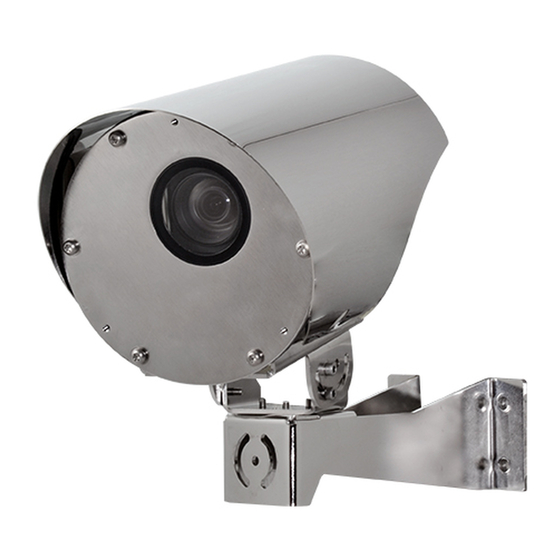
  • Page 92: Identification

    5 Identification 5.1.2 NTX NTX est une caméra IP aux propriétés anticorrosion 5.1 Description et désignation du supérieures. produit La caméra thermique offre une solution pour la vision, même dans le noir le plus total, le brouillard, la 5.1.1 NVX pluie, la fumée, ou pour les grandes distances.
  • Page 93: Marquage Du Produit

    Avant de procéder à l’installation, contrôler que Cette version du produit comprend la fonction le matériel fourni correspond à la commande et d’analyse vidéo VIDEOTEC Analytics. examiner les étiquettes de marquage. 6.2 NTX Ne procéder sous aucun prétexte à des modifications ou des connexions non prévues dans ce manuel.
  • Page 94: Identification Du Modèle

    Conforme à ONVIF, Profil Q, Profil S et jour/nuit, FULL HD 1080p, 30x, analyses vidéo intégrées Profil T de technologie DELUX (sans VIDEOTEC ANALYTICS) Caméra SONY FCB-EV7520, FULL Sans éssuie- glace/Fenêtre en Avec fonctions de Conforme à ONVIF, Profil S et Profil T...
  • Page 95: Préparation Du Produit En Vue De L'utilisation

    7 Préparation du produit en 7.3 Contenu vue de l’utilisation Contrôler que le contenu correspond à la liste matériel indiquée ci-dessous: Toute modification non approuvée • Caméra expressément par le fabricant entraînera • Support de fixation l’annulation de la garantie. •...
  • Page 96: Opérations À Effectuer Avant L'installation

    7.4 Opérations à effectuer avant 7.4.1 Montage au mur, au parapet ou au plafond l’installation Le produit peut être installé au mur, au parapet ou au plafond. ATTENTION! L’installation et l’entretien du dispositif doivent être effectués Fixez le support de fixation (01) sur la surface de exclusivement par un personnel technique destination finale.
  • Page 97 Fig. 9 Fixation sur parapet. Fig. 10 Fixation au plafond. Pour l'installation au plafond, le toit pare- soleil doit être démonté. MNVCNVX_2110_FR...
  • Page 98: Options D'installation

    7.4.2 Options d'installation Le produit peut être installé dans les positions décrites ci-dessous. La plage d'inclinaison verticale de la caméra est de -90° jusqu’à 0°. Fig. 13 Exemple d'installation sur parapet, rotation verticale, 0°. Fig. 11 Exemple d'installation murale, rotation verticale, 0°. Fig.
  • Page 99 Le produit peut être fixé avec une chaîne ou un fil L’option d'installation au plafond nécessite métallique afin d'éviter la chute de la caméra en cas de retirer le toit pare-soleil. d'affaissement du support. À cet effet le trou peut être utilisé...
  • Page 100: Installation

    (connecteurs souples). raccordés. Ethernet CONN 1 CONN 2 VIDEOTEC conseille de tester la configuration et les performances de l'appareils avant de placer celui-ci sur le lieu d'installation définitive. 8.1 Mise à la terre fonctionnelle Si l'unité est alimentée par la ligne Ethernet (PoE+) il est recommandé...
  • Page 101: Câblage Des Connecteurs Souples (Alimentation, I/O)

    8.2.1 Câblage des connecteurs souples La polarité de la tension appliquée aux (alimentation, I/O) broches 1 et 2 du connecteur 2 n’est pas pertinente. Le dispositif doit être alimenté au moyen d’un réseau à 24Vac ou 24Vdc. La mise à la terre n'est pas prévue car le produit ne le requiert pas lorsqu'il est Branchez le dispositif par le biais de la ligne alimenté...
  • Page 102: Branchement Des Relais

    Desserrez les vis sur les bornes (04) à l'avant du Avant de fixer les connecteurs souples aux connecteur, insérez les conducteurs et fixez-les en connecteurs correspondants à l’arrière de la caméra, serrant les vis. Vissez le corps du connecteur (03) à la assurez-vous que les TAP coïncident.
  • Page 103: Câblage Du Connecteur Souple (Ethernet, Poe+)

    8.2.3 Câblage du connecteur souple Effectuer les branchements selon ce qui est décrit dans le tableau (conforme au standard: TIA/EIA- (Ethernet, PoE+) 568-B). Si le dispositif n’est pas équipé d’une carte pour analyse vidéo, il peut être alimenté par le biais d’un PSE (Power Sourcing Equipment) conforme à...
  • Page 104: Branchement Du Câble De Réseau Ethernet

    8.2.4 Branchement du câble de réseau Tirez légèrement sur le câble Ethernet (05) jusqu'à ce que le connecteur RJ45 (06) soit complètement inséré Ethernet dans le corps du connecteur souple. La tresse du câble Ethernet du côté Après avoir inséré la cage et le joint, serrez l'écrou utilisateur doit toujours être connectée à...
  • Page 105: Configuration

    La page d'accueil sera affichée au premier accès. Pour la configuration de l'interface web, veuillez vous reporter au manuel d’instruction relatif à la version du firmware installé, disponible sur la page web du Fig. 33 produit sur www.videotec.com. MNVCNVX_2110_FR...
  • Page 106: Bride De Support Pour Projecteur Led

    GEKO IRH. Fig. 34 11.4 Adaptateur de fixation 11.2 Bride de support pour d'angle projecteur LED Pour installer le projecteur à LED VIDEOTEC GEKO IRH, vous pouvez équiper l’appareil d’une bride de support. Fig. 37 UEAC. 11.5 Collier de fixation sur poteau Fig.
  • Page 107: Contre-Plaque

    11.6 Contre-plaque 12 Entretien La contre-plaque peut servir pour le montage au Sectionner l’alimentation électrique avant mur ou au plafond, et pour des applications avec toute intervention technique sur l’appareil. une goulotte. Les quatre trous avec entre-axes élargi offrent une plus grande résistance mécanique. ATTENTION! L’installation et l’entretien du dispositif doivent être effectués exclusivement par un personnel technique...
  • Page 108: Ouverture Et Fermeture De La Caméra

    12.2 Ouverture et fermeture de la 12.3 Description de la carte de la caméra caméra Pour effectuer certaines opérations de maintenance, DESCRIPTION DE LA CARTE vous devez ouvrir la caméra. Connecteur/ Fonction Borne Faites glisser délicatement la glissière Fusible frontale. Veillez à ne pas endommager les câbles de connexion internes.
  • Page 109: Substitution Du Fusible

    12.4 Substitution du fusible 12.5 Factory Default ATTENTION! Pour assurer la protection Une fois la procédure de standard usine contre le risque d'incendie, remplacer les terminée, il faut configurer l'unité selon la fusibles avec le même type et valeur. Les description du chapitre correspondant ( fusibles doivent etre remplacer seulement 10.1 Adresse IP par défaut, page 23).
  • Page 110: Nettoyage

    13 Nettoyage 14 Informations sur l'élimination et le recyclage La fréquence des interventions dépend du type d’environnement dans lequel le La Directive Européenne 2012/19/UE sur les déchets caisson est utilisé. d'équipements électriques et électroniques (DEEE) exige que ces dispositifs ne doivent pas être éliminés 13.1 Propreté...
  • Page 111: Données Techniques

    (fps) • Épaisseur: 3mm • Serveur Web 15.1.4 Électrique • Motion Detection • Analyses vidéo: VIDEOTEC ANALYTICS (en option) Tension d’alimentation/Courant absorbé: • QoS: DSCP différenciés pour le streaming et la • 24Vac, 1.32A, 50/60Hz gestion du périphérique • 24Vdc, 0.9A •...
  • Page 112: Caméras

    15.1.8 Caméras SONY FCB-EV7520 Day/Night Full HD 30x Résolution: Full HD 1080p (1920x1080) Day/Night Full HD 30x DELUX Capteur d'image: 1/2.8" Exmor™ R CMOS sensor Résolution: Full HD 1080p (1920x1080) Pixels effectifs: environ 2.13 Megapixels Capteur d'image: 1/2.8" Exmor™ R CMOS sensor Éclairage minimum: Pixels effectifs: environ 2.38 Megapixels •...
  • Page 113: Environnement

    15.1.9 Environnement 15.1.11 Certifications - Applications ferroviaires Installation d'intérieur et d'extérieur Les versions avec VIDEOTEC ANALYTICS ne sont pas certifiées pour les Température de fonctionnement applications ferroviaires • Version avec l'alimentation 24Vac ou 24Vdc: de Conformité à la norme pour les applications -40°C jusqu'à...
  • Page 114: Ntx

    15.2 NTX 15.2.5 Réseau Connexion Ethernet: 100 Base-TX 15.2.1 Généralités Connecteur: RJ45 Installation simple par les connecteurs rapides 15.2.6 Vidéo Configuration rapide Encodeur vidéo 15.2.2 Mécanique • Protocole de communication: ONVIF, Profil Q Profil Construction en acier inox AISI 316L S et Profil T, ONVIF Thermal Service Œillet pour chaîne de sécurité...
  • Page 115: Caméras

    15.2.8 Caméras CAMÉRAS THERMIQUES (RÉSOLUTION 336X256) Objectif 9mm Objectif 13mm Objectif 19mm Objectif 25mm Objectif 35mm Capteur d'image Microbolomètre non Microbolomètre non Microbolomètre non Microbolomètre non Microbolomètre non refroidi VOx refroidi VOx refroidi VOx refroidi VOx refroidi VOx Résolution interpolée 720x480 720x480 720x480...
  • Page 116 FR - Français - Manuel d’instructions CAMÉRAS THERMIQUES (RÉSOLUTION 640X512) Objectif 9mm Objectif 13mm Objectif 19mm Objectif 25mm Objectif 35mm Capteur d'image Microbolomètre non Microbolomètre non Microbolomètre non Microbolomètre non Microbolomètre non refroidi VOx refroidi VOx refroidi VOx refroidi VOx refroidi VOx Résolution interpolée 720x480...
  • Page 117: Environnement

    15.2.9 Environnement 15.2.11 Certifications - Applications ferroviaires Installation d'intérieur et d'extérieur Conformité à la norme pour les applications Température de fonctionnement ferroviaires: EN50121-4 (seulement avec • Version avec l'alimentation 24Vac ou 24Vdc: de l'alimentation 24Vac ou 24Vdc) -40°C jusqu'à +65°C 15.2.12 Certifications - Applications •...
  • Page 118 16 Dessins techniques Les tailles indiquées sont en millimètres. Ø 168 Ø 65 268.2 330.7 Fig. 45 NVX, fixation murale. Ø 8.5 Ø 168 268.2 Ø 65 Fig. 46 NVX, fixation sur parapet. MNVCNVX_2110_FR...
  • Page 119 Ø 65 243.4 Ø 168 188.9 Ø 8.5 Fig. 47 NVX, fixation au plafond. Ø 168 Ø 40 268.2 330.7 Fig. 48 NTX, fixation murale. MNVCNVX_2110_FR...
  • Page 120 Ø 8.5 Ø 168 268.2 Ø 40 Fig. 49 NTX, fixation sur parapet. Ø 40 215.4 Ø 168 160.9 Ø 8.5 Fig. 50 NTX, fixation au plafond. MNVCNVX_2110_FR...
  • Page 122 Headquarters Italy Videotec S.p.A. Via Friuli, 6 - I-36015 Schio (VI) - Italy Tel. +39 0445 697411 - Fax +39 0445 697414 Email: info@videotec.com www.videotec.com MNVCNVX_2110_FR...
  • Page 123 DEUTSCH Rostfreiem Stahl Kamera Deutsch - Bedienungsanleitung...
  • Page 125 6.1 NVX ......................................11 6.1.1 Version mit integriertem Scheibenwischer ..........................11 6.1.2 Version ohne Scheibenwischer .................................11 6.1.3 Day/Night-Kamera ....................................11 6.1.4 VIDEOTEC ANALYTICS ..................................11 6.2 NTX ......................................11 6.2.1 Fensterscheibe aus Germanium ...............................11 6.3 Identifizierung des Modells ..............................12 7 Vorbereitung des Produktes auf den Gebrauch ..............13 7.1 Entfernen der Verpackung ..............................13...
  • Page 126 11 Zubehör und Support ......................23 11.1 Waschanlage ..................................23 11.2 Bügelhalterung für LED-Scheinwerfer ........................24 11.3 LED- Scheinwerfer ................................24 11.4 Winkeladaptermodul ................................24 11.5 Massive Mastschelle ................................24 11.6 Gegenplatte ..................................25 11.7 Frontaler Staubschutzschild ............................25 12 Wartung ..........................25 12.1 Sonnenschutzdach entfernen ............................25 12.2 Öffnen und Schließen der Kamera ..........................26 12.3 Beschreibung der Kameraplatine ..........................26 12.4 Sicherung austauschen ..............................27 12.5 Factory Default ...................................27...
  • Page 127 15.2.12 Zertifizierungen - Marine-Anwendungen..........................35 16 Technische Zeichnungen......................36 MNVCNVX_2110_DE...
  • Page 128 MNVCNVX_2110_DE...
  • Page 129: Allgemeines

    Videoüberwachung her, die ausschließlich für den GEFAHR! gewerblichen Gebrauch bestimmt sind. Die Produkte Heiße Oberfläche. von VIDEOTEC S.p.A. können in einem technischen Nicht berühren. Die Oberflächen sind Zusammenhang und für vielfältige unterschiedliche heiß und können bei Berührung zu Zwecke verwendet werden. Hierzu zählen u. a. die Verbrennungen führen.
  • Page 130: Sicherheitsnormen

    Firmware dieser Geräte automatisch über das Internet aktualisiert wird. • Der Hersteller lehnt jede Haftung für eventuelle VIDEOTEC S.p.A. kann im Laufe der Zeit Sicherheits- Schäden ab, die aufgrund unsachgemäßer Updates für die eigenen Geräte herausbringen, die Anwendung der in diesem Handbuch erwähnten...
  • Page 131 • Unter keinen Umständen dürfen Veränderungen • Zur Spannungsversorgung des oder Anschlüsse vorgenommen werden, die Produktes verwenden Sie bitte einen in diesem Handbuch nicht genannt sind. Der Sicherheitstransformator und / oder eine isolierte Gebrauch ungeeigneten Geräts kann die Sicherheit Gleichspannungsquelle mit sachgerechten Merkmalen.
  • Page 132: Identifizierung

    5 Identifizierung 5.1.2 NTX NTX ist eine IP Wärmebildkamera mit hohen 5.1 Beschreibung und korrosionsbeständigen Eigenschaften. Bezeichnung des Produktes Die thermische Videokamera ermöglicht die Sicht auch bei vollständiger Dunkelheit, Nebel, Regen, 5.1.1 NVX Rauch oder auf große Entfernungen. Die Fensterscheibe aus Germanium hat eine NVX ist eine Super low-light Full HD IP-Kamera mit Kretzfeste Außenbehandlung, Antireflex, Hard hohen korrosionsbeständigen Eigenschaften heraus.
  • Page 133: Kennzeichnung Des Produkts

    6.1.4 VIDEOTEC ANALYTICS Vor Beginn der Installationsarbeiten ist zu kontrollieren, ob das Bei dieser Produktausführung wird die gelieferte Material den jeweiligen Anforderungen entspricht. Videoanalysefunktion VIDEOTEC Analytics integriert. Zu erkennen ist dies anhand der Kennzeichnungsschilder. 6.2 NTX Unter keinen Umständen dürfen Veränderungen oder Anschlüsse vorgenommen werden, die in diesem Handbuch...
  • Page 134: Identifizierung Des Modells

    24Vac/24Vdc/PoE+ Kamera super low-light Day/ Mit Scheibenwischer Ohne integrierten Videoanalyse- In Übereinstimmung mit ONVIF, Night, FULL HD 1080p, 30x, funktionen (ohne VIDEOTEC Profil Q, Profil S und Profil T mit DELUX-Technologie ANALYTICS) Kamera SONY FCB-EV7520, Ohne Wischer/Glasfenster Mit integrierten Videoa- In Übereinstimmung mit ONVIF,...
  • Page 135: Vorbereitung Des Produktes Auf Den Gebrauch

    7 Vorbereitung des 7.3 Inhalt Produktes auf den Gebrauch Prüfen Sie, ob der Inhalt mit der nachstehenden Materialliste übereinstimmt: Jede vom Hersteller nicht ausdrücklich • Kamera genehmigte Veränderung führt zum Verfall • Befestigungshalterung der Gewährleistungsrechte. • Drehhalterung 7.1 Entfernen der Verpackung •...
  • Page 136: Auf Die Installation Vorbereitende Tätigkeiten

    7.4 Auf die Installation 7.4.1 Befestigung an Wand, Geländer oder Decke vorbereitende Tätigkeiten Das Produkt ist für die Montage an der Wand, am Geländer oder an der Decke geeignet. ACHTUNG! Die Installation und Wartung der Vorrichtung ist technischen Fachleuten Die Befestigungshalterung (01) auf der Oberfläche vorbehalten.
  • Page 137 Abb. 9 Befestigung an der Brüstung. Abb. 10 Deckenbefestigung. Bei der Montage an der Decke ist das Sonnenschutzdach abzumontieren. MNVCNVX_2110_DE...
  • Page 138: Montageoptionen

    7.4.2 Montageoptionen Das Produkt kann in den nachfolgend angegebenen Positionen installiert werden. Der vertikale Neigungsbereich der Kamera reicht von -90° bis 0°. Abb. 13 Beispiel Geländermontage, Vertikale Drehung, 0°. Abb. 11 Beispiel Wandmontage, Vertikale Drehung, 0°. Abb. 14 Beispiel Geländermontage, Vertikale Drehung, -90°. Abb.
  • Page 139 Das Produkt kann mit einer Kette oder einem Bei der Option der Deckenmontage muss Metalldraht festgemacht werden, um so einem das Sonnenschutzdach entfernt werden. Herunterfallen der Kamera vorzubeugen, sollte die Halterung nachgeben. Hierzu kann das Loch verwendet werden, siehe Abbildung (Abb. 17, Seite 17).
  • Page 140: Installation

    Steckverbinder). Alle nicht angeschlossenen Drähte sind elektrisch zu isolieren. Ethernet CONN 1 CONN 2 VIDEOTEC empfiehlt, vor der endgültigen Montage am Installationsort die Konfiguration und die Leistungen des Gerätes zu prüfen. 8.1 Funktionelle Erdung Wenn die Einheit über die Ethernetleitung (PoE+) versorgt wird, sollte für eine...
  • Page 141: Verkabelung Der Losen Steckverbinder (Netzteil, I/O)

    8.2.1 Verkabelung der losen Die am Pin 1 und 2 des Steckverbinders Steckverbinder (Netzteil, I/O) 2 angewandte Spannungspolarität ist irrelevant. Das Gerät mit einem Versorgungsnetz mit 24Vac oder 24Vdc versorgen. Die Erdung ist nicht vorgesehen, da sie das Produkt nicht benötigt, wenn es mit 24Vac Das Gerät mit einer Ethernetleitung oder 24VVdc gespeist wird.
  • Page 142: Anschluss Der Relais

    Die vorhandenen Schrauben der Klemmen (04) im Bevor die losen Steckverbinder an den vorderen Bereich des Steckverbinders lösen. Die entsprechenden Steckverbindern auf der Rückseite Leiter einführen und diese durch Anziehen der der Kamera befestigt werden, sicherstellen, dass die Schrauben befestigen. Den Steckverbinderkorpus TAP-Anschlüsse übereinstimmen.
  • Page 143: Verkabelung Des Losen Steckverbinders (Ethernet, Poe+)

    8.2.3 Verkabelung des losen Die Anschlüsse nach den Angaben in der Tabelle vornehmen (standardgerecht: TIA/EIA-568-B). Steckverbinders (Ethernet, PoE+) Wenn das Gerät über eine Platine für die Videoanalyse verfügt, kann es mit PSE (Power Sourcing Equipment) in Überstimmung mit IEEE 802.3at (PoE+). RJ45 Ethernetkabel mit den nachfolgend Pin8...
  • Page 144: Einschaltung

    8.2.4 Anschluss des Ethernet-Kabels Das Ethernetkabel (05) leicht anziehen bis der Steckverbinder RJ45 (06) nicht vollständig in die Das Abschirmgeflecht des Ethernetkabels Aufnahme des Korpus des losen Steckverbinders muss benutzerseitig stets geerdet sein. gesteckt ist. Einen geschirmten Steckverbinder RJ45 Nachdem der Käfig und die Dichtung aufgesteckt verwenden.
  • Page 145: Konfiguration

    Browser mit der Adresse http://indirizzo_ip herzustellen. Beim ersten Zugriff wird die Startseite angezeigt. Informationen zur Konfiguration der Webschnittstelle finden Sie im Handbuch, das sich auf die installierte Firmware- Version bezieht. Das Handbuch ist auf der Abb. 33 Produktwebseite in www.videotec.com verfügbar. MNVCNVX_2110_DE...
  • Page 146: Bügelhalterung Für Led-Scheinwerfer

    Abb. 36 GEKO IRH. 11.4 Winkeladaptermodul Abb. 34 11.2 Bügelhalterung für LED- Scheinwerfer Für die Installation der GEKO IRH LED-Scheinwerfer von VIDEOTEC muss das Gerät mit einer Bügelhalterung ausgestattet werden. Abb. 37 UEAC. 11.5 Massive Mastschelle Abb. 35 NVXIRBKT. Abb. 38 UEAP.
  • Page 147: Gegenplatte

    11.6 Gegenplatte 12 Wartung Die Gegenplatte kann für die Wand- oder Vor technischen Eingriffen am Gerät Deckenmontage verwendet werden, auch für muss die Stromversorgung unterbrochen Anwendungen mit Rohr. Die vier Löcher mit werden. vergrößertem Achsabstand ermöglichen einen höheren mechanischen Widerstand. ACHTUNG! Die Installation und Wartung der Vorrichtung ist technischen Fachleuten vorbehalten.
  • Page 148: Öffnen Und Schließen Der Kamera

    12.2 Öffnen und Schließen der 12.3 Beschreibung der Kamera Kameraplatine Um einige Wartungsarbeiten durchzuführen, muss BESCHREIBUNG DER PLATINE die Kamera geöffnet werden. Verbinder/ Funktion Klemme Den vorderen Schlitten vorsichtig Sicherung entfernen. Darauf achten, die inneren Verbindungskabel nicht zu beschädigen. Reset-Dipschalter Tab.
  • Page 149: Sicherung Austauschen

    12.4 Sicherung austauschen 12.5 Factory Default ACHTUNG! Damit ein ständiger Wenn die Factory-Default-Prozedur einmal Brandschutz garantiert wird, sind die abgeschlossen ist, muss die Einheit wie Sicherungen nur in dem gleichen Typ und im entsprechenden Kapitel beschrieben Wert zu ersetzen. Die Sicherungen sind nur konfiguriert werden (10.1 Vorgegebene IP- von Fachleuten zu ersetzen.
  • Page 150: Reinigung

    13 Reinigung 14 Informationen bezüglich Entsorgung und Recycling Die Häufigkeit der Eingriffe hängt von der Umgebung ab, in der die Einheit verwendet Die EU-Richtlinie 2012/19/ЕU über Elektro- und wird. Elektronik-Altgeräte (WEEE) verpflichtet, dass diese Geräte nicht zusammenn mit festen 13.1 Fensterreinigung Haushaltsabfällen entsorgt werden sollten.
  • Page 151: Technische Daten

    VIDEOTEC Analytics verfügbar 15.1.7 I/O-Schnittstelle Leistungsaufnahme I/O Alarm-Karte (version mit Scheibenwischer) • Ausführungen ohne VIDEOTEC Analytics: 21W • Eingang zum Zurücksetzen von fern: 1 • Ausführungen mit VIDEOTEC Analytics: 25.2W • Relais-Ausgänge: 1+1 (1 Relais nur für die Scheibenwaschpumpe und ein konfigurierbares...
  • Page 152: Kamera

    15.1.8 Kamera SONY FCB-EV7520 Day/Night Full HD 30x Auflösung: Full HD 1080p (1920x1080) Day/Night Full HD 30x DELUX Image Sensor: 1/2.8" Exmor™ R CMOS sensor Auflösung: Full HD 1080p (1920x1080) Effektive Pixel: ca. 2.13 Megapixels Image Sensor: 1/2.8" Exmor™ R CMOS sensor Mindestbeleuchtung: Effektive Pixel: ca.
  • Page 153: Umgebung

    15.1.9 Umgebung 15.1.11 Zertifizierungen - Bahnanwendungen Montage für den Innen- und Außenbereich Die Ausführungen mit VIDEOTEC ANALYTICS sind für Anwendungen Betriebstemperatur beim Zugverkehr nicht zertifiziert • Version mit 24Vac- oder 24Vdc-Spannungsverso In Übereinstimmung mit den Vorschriften für rgung: von -40°C bis zu +65°C (bis zu +50°C, für Anwendungen beim Zugverkehr: EN50121-4 (nur mit Ausführungen mit VIDEOTEC ANALYTICS)
  • Page 154: Ntx

    15.2 NTX 15.2.5 Netzwerk Ethernet-Verbindung: 100 Base-TX 15.2.1 Allgemeines Verbinder: RJ45 Einfache Montage durch Schnellanschlüsse 15.2.6 Video Schnelle Einrichtung und Setup Video-Encoder 15.2.2 Mechanik • Kommunikationsprotokoll: ONVIF, Profil Q, Profil S Hergestellt aus rostfreiem Stahl AISI 316L und Profil T, ONVIF Thermal Service Langloch für die Sicherheitskette •...
  • Page 155: Kamera

    15.2.8 Kamera WÄRMEBILDKAMERAS (AUFLÖSUNG 336X256) Objectiv 9mm Objectiv 13mm Objectiv 19mm Objectiv 25mm Objectiv 35mm Image Sensor Ungekühltes Vanadiu- Ungekühltes Vanadiu- Ungekühltes Vanadiu- Ungekühltes Vanadiu- Ungekühltes Vanadiu- moxid-Mikrobolometer moxid-Mikrobolometer moxid-Mikrobolometer moxid-Mikrobolometer moxid-Mikrobolometer (VOx) (VOx) (VOx) (VOx) (VOx) Interpolierte Auflösung 720x480 720x480 720x480 720x480...
  • Page 156 DE - Deutsch - Bedienungsanleitung WÄRMEBILDKAMERAS (AUFLÖSUNG 640X512) Objectiv 9mm Objectiv 13mm Objectiv 19mm Objectiv 25mm Objectiv 35mm Image Sensor Ungekühltes Vanadiu- Ungekühltes Vanadiu- Ungekühltes Vanadiu- Ungekühltes Vanadiu- Ungekühltes Vanadiu- moxid-Mikrobolometer moxid-Mikrobolometer moxid-Mikrobolometer moxid-Mikrobolometer moxid-Mikrobolometer (VOx) (VOx) (VOx) (VOx) (VOx) Interpolierte Auflösung 720x480 720x480...
  • Page 157: Umgebung

    15.2.9 Umgebung 15.2.11 Zertifizierungen - Bahnanwendungen Montage für den Innen- und Außenbereich In Übereinstimmung mit den Vorschriften für Betriebstemperatur Anwendungen beim Zugverkehr: EN50121-4 (nur mit • Version mit 24Vac- oder 24Vdc-Spannungsversorg 24Vac- oder 24Vdc-Spannungsversorgung) ung: von -40°C bis zu +65°C 15.2.12 Zertifizierungen - Marine- •...
  • Page 158 16 Technische Zeichnungen Die Maße sind in Millimetern angegeben. Ø 168 Ø 65 268.2 330.7 Abb. 45 NVX, Wandbefestigung. Ø 8.5 Ø 168 268.2 Ø 65 Abb. 46 NVX, befestigung an der Brüstung. MNVCNVX_2110_DE...
  • Page 159 Ø 65 243.4 Ø 168 188.9 Ø 8.5 Abb. 47 NVX, deckenbefestigung. Ø 168 Ø 40 268.2 330.7 Abb. 48 NTX, Wandbefestigung. MNVCNVX_2110_DE...
  • Page 160 Ø 8.5 Ø 168 268.2 Ø 40 Abb. 49 NTX, befestigung an der Brüstung. Ø 40 215.4 Ø 168 160.9 Ø 8.5 Abb. 50 NTX, deckenbefestigung. MNVCNVX_2110_DE...
  • Page 162 Headquarters Italy Videotec S.p.A. Via Friuli, 6 - I-36015 Schio (VI) - Italy Tel. +39 0445 697411 - Fax +39 0445 697414 Email: info@videotec.com www.videotec.com MNVCNVX_2110_DE...
  • Page 163 РУССКИЙ Камера защитой от коррозии Русский - Руководство по эксплуатации...
  • Page 165 6 Модели ...........................11 6.1 NVX ......................................11 6.1.1 Модель со встроенным стеклоочистителем ...........................11 6.1.2 Версия без стеклоочистителя ................................11 6.1.3 Камера Day/Night ....................................11 6.1.4 VIDEOTEC ANALYTICS ..................................11 6.2 NTX ......................................11 6.2.1 Германиевое окно ....................................11 6.3 Идентификация модели ..............................12 7 Подготовка устройства к использованию ................13 7.1 Распаковка...
  • Page 166 11 Принадлежности и опоры ....................23 11.1 Омыватель (Washer) ................................23 11.2 Опорный кронштейн для светодиодной подсветки ..................24 11.3 Светодиодный осветитель ............................24 11.4 Адаптер для крепления на угол ..........................24 11.5 Адаптер для установки на стойке ..........................24 11.6 Пластина крепления ...............................25 11.7 Передний козырек для защиты от пыли .......................25 12 Техническое...
  • Page 167 15.2.12 Сертификаты - Морское применение ...........................35 16 Технические чертежи ......................36 MNVCNVX_2110_RU...
  • Page 168 MNVCNVX_2110_RU...
  • Page 169: Настоящем Руководстве

    VIDEOTEC S.p.A. производит устройства Опасность механического повреждения. видеонаблюдения исключительно для Риск раздавливания или отрезания. профессионального применения. Продукция VIDEOTEC S.p.A. может использоваться в ОПАСНОСТЬ! технических областях для самых разных целей: Горячая поверхность. от контроля за городской безопасностью до Избегайте контакта. При контакте с...
  • Page 170: Правила Техники Безопасности

    невозможно и не рекомендуется, чтобы прошивка ПРЕДУПРЕЖДЕНИЕ! Для обеспечения этих устройств автоматически обновлялась постоянной защиты от риска возгорания через Интернет. VIDEOTEC S.p.A. со временем при замене предохранителей следует может выпускать обновления мер безопасности использовать предохранители для своих устройств, которые должны быть...
  • Page 171 • Никогда и ни при каких обстоятельствах не • Для питания устройства используется выполняйте изменений или подключений, не защитный трансформатор и (или) предусмотренных настоящим руководством. изолированный источник питания постоянного Ненадлежащее использование оборудования тока, обладающий соответствующими характеристиками. Выходная мощность не может привести к возникновению серьезных опасных...
  • Page 172: Обозначение

    5 Обозначение 5.1.2 NTX Модель NTX является тепловизионной камерой IP 5.1 Описание и обозначение имеющей высокую устойчивость к коррозии. типа устройства Тепловизор обеспечивает возможность наблюдения в полной темноте, при наличии 5.1.1 NVX тумана, дождя, задымленности или на дальнем расстоянии. Модель NVX является камерой FULL HD, созданной Германиевое...
  • Page 173: Маркировка Изделия

    6.1.4 VIDEOTEC ANALYTICS 5.3.1 Проверка маркировки Это исполнение продукта включает функцию Перед тем как продолжить установку, убедитесь, анализа видео VIDEOTEC Analytics. что предоставленные материалы соответствуют 6.2 NTX спецификациям заказа, проверив этикетки с маркировкой. Никогда и ни при каких обстоятельствах не выполняйте...
  • Page 174: Идентификация Модели

    1080p, 30x, с технологией DELUX VIDEOTEC ANALYTICS) Профилю S и Профилю T Камера SONY FCB-EV7520, FULL HD Без Со встроенной функцией Соответствие стандарту 1080p, 30x стеклоочистителя/Стеклянное анализа видеоданных (VIDEOTEC ONVIF, Профилю S и окно ANALYTICS) Профилю T Без стеклоочистителя/Окно из поликарбоната Табл. 1 NVX.
  • Page 175: Подготовка Устройства К Использованию

    7 Подготовка устройства к 7.3 Комплект оборудования использованию Проверьте комплект оборудования на соответствие представленному ниже списку материалов: Любое изменение, которое выполняется без разрешения, явным образом • Камера предоставленного производителем, • Кронштейн для фиксации аннулирует гарантию. • Поворотная опора 7.1 Распаковка •...
  • Page 176: Подготовительные Работы Перед Установкой

    7.4 Подготовительные работы 7.4.1 Установка на стене, парапете или потолке перед установкой Изделие можно установить на стене, парапете или ПРЕДУПРЕЖДЕНИЕ! Установка потолке. и обслуживание устройства Закрепите кронштейн для фиксации (01) на должны осуществляться только конечной поверхности установки. специализированным персоналом. Установите опору кожуха (03) на кожух с помощью четырех...
  • Page 177 Рис. 9 Крепление к парапету. Рис. 10 Крепление на потолок. При установке на потолок необходимо снять козырек. MNVCNVX_2110_RU...
  • Page 178: Варианты Установки

    7.4.2 Варианты установки Устройство может устанавливаться в представленных ниже положениях. Диапазон вертикального наклона кожуха составляет -90 °- 0 °. Рис. 13 Пример установки на парапете, вертикальное перемещение, 0°. Рис. 11 Пример установки на стене, вертикальное перемещение, 0°. Рис. 14 Пример установки на парапете, вертикальное перемещение, -90°.
  • Page 179 Изделие можно закрепить при помощи цепи или При установке на потолок козырек металлической проволоки, чтобы предотвратить необходимо снять. падение камеры в случае разрушения опоры. Для этой цели можно использовать отверстие, показанное на рисунке (Рис. 17, страница 17). Рис. 15 Пример установки на потолок, вертикальное Рис.
  • Page 180: Монтаж

    осуществляться со стороны кабеля (штепсельные необходимости. разъемы). Ethernet CONN 1 CONN 2 Все неподключенные провода должны быть изолированы. VIDEOTEC настоятельно рекомендует проверить конфигурацию и эксплуатационные характеристики устройства перед его окончательной установкой в соответствующем месте. 8.1 Функциональное заземление Рис. 19 Вид кожуха сзади. Разъемы на сторонах кожуха.
  • Page 181: Кабельная Проводка Для Штепсельного Соединения (Источник Питания, I/O)

    8.2.1 Кабельная проводка для Полярность напряжения на контактах 1 и штепсельного соединения (источник 2 разъема 2 не имеет значения. питания, I/O) Заземление не предусмотрено, Питание устройства осуществляется от поскольку изделию оно не требуется, так источника питания 24Vac или 24Vdc. как для его питания используется 24Vac или...
  • Page 182: Подключение Реле

    Ослабьте винты на клеммах (04) лицевой стороны Перед тем как подсоединить штепсельные разъема, вставьте провода и зафиксируйте их, разъемы к соответствующим разъемам на задней затянув винты. Закрепите корпус разъема (03) на стороне кожуха, убедитесь, что TAP плотно лицевой стороне с помощью зажимов (05), затянув прилегает.
  • Page 183: Кабельная Проводка Для Штепсельного Разъема (Ethernet, Poe+)

    8.2.3 Кабельная проводка для Выполните подключение в соответствии с приведенным в таблице описанием (с учетом штепсельного разъема (Ethernet, стандартных технических требований: TIA/EIA- PoE+) 568-B). Если устройство не оснащено платой видеоанализа, его можно питать, используя PSE (Power Sourcing Equipment), совместимое с IEEE 802.3at (PoE+).
  • Page 184: Включение

    8.2.4 Подключение Ethernet-кабеля Слегка подергайте кабель Ethernet (05), пока разъем RJ45 (06) не будет полностью вставлен в Оплетка кабеля Ethernet со стороны корпус разъема для hавесной соединитель. пользователя должна быть После установки каркаса и прокладки затяните постоянно заземлена. Используйте уплотнительную гайку (07). экранированный...
  • Page 185: Конфигурация

    Чтобы войти в веб-интерфейс устройства, просто используйте браузер для подключения к адресу http://ip_address. При первом входе будет отображаться Главная страница. Информацию о настройке веб- интерфейса см. в руководстве, относящемуся к установленной версии Рис. 33 прошивки, которое доступно на нашем веб-сайте www.videotec.com. MNVCNVX_2110_RU...
  • Page 186: Опорный Кронштейн Для Светодиодной Подсветки

    Рис. 36 GEKO IRH. Рис. 34 11.4 Адаптер для крепления на 11.2 Опорный кронштейн для угол светодиодной подсветки Для установки светодиодных осветитель VIDEOTEC GEKO IRH, на устройство необходимо установить опорный кронштейн. Рис. 37 UEAC. 11.5 Адаптер для установки на стойке...
  • Page 187: Пластина Крепления

    11.6 Пластина крепления 12 Техническое обслуживание Пластину крепления можно использовать для установки на стену или потолок, а также на кабель-каналы. Увеличенное расстояние между Отключите источник питания, перед тем четырьмя отверстиями обеспечивает большую как приступить к проведению каких- механическую прочность. либо технических работ на устройстве. ПРЕДУПРЕЖДЕНИЕ! Установка...
  • Page 188: Открытие И Закрытие Кожуха

    12.2 Открытие и закрытие 12.3 Описание платы камеры кожуха ОПИСАНИЕ ПЛАТЫ Разъем/ Функция Для выполнения ряда работ по техническому Клемма обслуживанию необходимо открыть камеру Предохранитель Осторожно открутите направляющую DIP-переключатель сброса на лицевой стороне. Соблюдайте осторожность, чтобы не повредить Табл. 7 внутренние...
  • Page 189: Замена Предохранителя

    12.4 Замена предохранителя 12.5 Factory Default ПРЕДУПРЕЖДЕНИЕ! Для обеспечения После установки заводских настроек постоянной защиты от риска возгорания устройство должно быть настроено так, при замене предохранителей следует как описано в соответствующей главе ( использовать предохранители 10.1 IP-адрес по умолчанию, страница того...
  • Page 190: Очистка

    13 Очистка 14 Информация об утилизации и переработке Частота операций зависит от среды эксплуатации изделия. Европейская директива 2012/19/ЕС Об Отходах Электрического и Электронного оборудования 13.1 Очистка стекла (RAEE) предписывает, что данные устройства не следует утилизировать вместе с твердыми Не используйте этиловый спирт, бытовыми...
  • Page 191: Технические Характеристики

    • PoE+ (IEEE 802.3at), недоступно для исполнения • Вход для дистанционного сброса: 1 с VIDEOTEC Analytics • Выходы реле: 1+1 (1 реле для насоса омывателя Энергопотребление и одно настраиваемое, 1A, 30Vac/60Vdc max) • Исполнения без VIDEOTEC Analytics: 21W • Исполнения с VIDEOTEC Analytics: 25.2W MNVCNVX_2110_RU...
  • Page 192: Камеры

    15.1.8 Камеры SONY FCB-EV7520 Day/Night Full HD 30x Разрешение: Full HD 1080p (1920x1080) Day/Night Full HD 30x DELUX Датчик изображения: 1/2.8" Exmor™ R CMOS sensor Разрешение: Full HD 1080p (1920x1080) Эффективные пиксели: приблизительно 2.13 Megapixels Датчик изображения: 1/2.8" Exmor™ R CMOS sensor Минимальное...
  • Page 193: Окружающая Среда

    Наружная установка (CE): EN60950-22, IEC60950-22 Степень защиты IP (EN60529): IP66, IP67, IP68 (2h30 min, 2m), IP69 Сертификат UL (недействительно для исполнений с VIDEOTEC Analytics): cULus Listed, TYPE 4X, TYPE 6P Сертификат EAC Сертификат KC (сертификат распространяется только на следующие коды: NVX2xxxxxJ)
  • Page 194: Ntx

    15.2 NTX 15.2.5 Сеть Ethernet подключение: 100 Base-TX 15.2.1 Общие сведения Разъем: RJ45 Простая установка благодаря быстроразъемному 15.2.6 Видео подключению Видеокодер Быстрая настройка и установка • Протокол связи: ONVIF, Profile Q, Profile S и 15.2.2 Механические хар. Profile T, ONVIF Thermal Service Конструкция...
  • Page 195: Камеры

    15.2.8 Камеры ТЕПЛОВИЗОРЫ (РАЗРЕШЕНИЕ 336X256) Объектив 9mm Объектив 13mm Объектив 19mm Объектив 25mm Объектив 35mm Датчик изображения Неохлаждаемый Неохлаждаемый Неохлаждаемый Неохлаждаемый Неохлаждаемый микроболометр (на микроболометр (на микроболометр (на микроболометр (на микроболометр (на оксиде ванадия - VOx) оксиде ванадия - VOx) оксиде...
  • Page 196 RU - Русский - Руководство по эксплуатации ТЕПЛОВИЗОРЫ (РАЗРЕШЕНИЕ 640X512) Объектив 9mm Объектив 13mm Объектив 19mm Объектив 25mm Объектив 35mm Датчик изображения Неохлаждаемый Неохлаждаемый Неохлаждаемый Неохлаждаемый Неохлаждаемый микроболометр (на микроболометр (на микроболометр (на микроболометр (на микроболометр (на оксиде ванадия - VOx) оксиде...
  • Page 197: Окружающая Среда

    15.2.9 Окружающая среда 15.2.11 Сертификаты - Применение на железной дороге Для установки внутри помещений и наружной установки Соответствие нормативным требованиям для применения на железной дороге: EN50121-4 Рабочая температура (только с питанием 24 В переменного тока или 24 В • Версия с питанием 24Vac переменного тока или постоянного...
  • Page 198 16 Технические чертежи Размеры указаны в миллиметрах. Ø 168 Ø 65 268.2 330.7 Рис. 45 NVX, установка на стену. Ø 8.5 Ø 168 268.2 Ø 65 Рис. 46 NVX, крепление к парапету. MNVCNVX_2110_RU...
  • Page 199 Ø 65 243.4 Ø 168 188.9 Ø 8.5 Рис. 47 NVX, крепление на потолок. Ø 168 Ø 40 268.2 330.7 Рис. 48 NTX, установка на стену. MNVCNVX_2110_RU...
  • Page 200 Ø 8.5 Ø 168 268.2 Ø 40 Рис. 49 NTX, крепление к парапету. Ø 40 215.4 Ø 168 160.9 Ø 8.5 Рис. 50 NTX, крепление на потолок. MNVCNVX_2110_RU...
  • Page 202 Headquarters Italy Videotec S.p.A. Via Friuli, 6 - I-36015 Schio (VI) - Italy Tel. +39 0445 697411 - Fax +39 0445 697414 Email: info@videotec.com www.videotec.com MNVCNVX_2110_RU...
  • Page 204 Headquarters Italy Videotec S.p.A. Via Friuli, 6 - I-36015 Schio (VI) - Italy Tel. +39 0445 697411 - Fax +39 0445 697414 Email: info@videotec.com www.videotec.com MNVCNVX_2110 MNVCNVX_2110...

Table des Matières