Table des Matières
Publicité
Les langues disponibles
Les langues disponibles
Liens rapides
ENGLISH
MAXIMUS MPXHD DELUX
Explosion-proof PTZ FULL HD camera with new DELUX technology,
EN
English - Instruction manual
IT
Italiano - Manuale di istruzioni
FR
Français - Manuel d'instructions
DE
Deutsch - Bedienungsanleitung
for day/night viewing with exceptional night brightness
RU
Русский - Руководство по эксплуатации
PT
Português - Manual de instruções
KO
한국어 - 지침 설명서
Publicité
Chapitres
Table des Matières
Dépannage

Manuels Connexes pour Videotec MAXIMUS MPXHD DELUX


Sommaire des Matières pour Videotec MAXIMUS MPXHD DELUX
- Page 1 ENGLISH MAXIMUS MPXHD DELUX Explosion-proof PTZ FULL HD camera with new DELUX technology, for day/night viewing with exceptional night brightness English - Instruction manual Italiano - Manuale di istruzioni Русский - Руководство по эксплуатации Français - Manuel d’instructions Português - Manual de instruções 한국어...
- Page 3 ENGLISH MAXIMUS MPXHD DELUX Explosion-proof FULL HD PTZ camera with new DELUX technology, for day/night viewing with exceptional night brightness English - Instruction manual...
-
Page 5: Table Des Matières
Contents E N G L I S H 1 About this manual ........................7 1.1 Typographical conventions............................... 7 2 Notes on copyright and information on trademarks ............7 3 Note on data security ......................7 3.1 Introduction ................................... 7 3.2 Security functionalities which can be enabled in the product ................8 3.2.1 Authentication credentials .................................8 3.2.2 Encryption ........................................8 4 Safety rules.......................... - Page 6 8.1.2 Safety rules ......................................23 8.1.3 Explosion prevention rules ................................23 9 Switching on ......................... 24 9.1 Before powering the product in an explosive atmosphere ................24 10 Configuration ........................25 10.1 Default IP address ................................25 10.2 Web interface ..................................25 10.2.1 First access to the web pages ............................... 25 10.2.2 Home Page......................................
- Page 7 16.2 Mechanical ..................................39 16.3 Electrical ....................................39 16.4 Network ....................................39 16.5 Video .....................................39 16.6 I/O interface ..................................39 16.7 Cameras ....................................40 16.8 Environment ..................................40 16.9 Certifications ..................................40 16.10 Electrical rating ................................41 17 Technical drawings ......................41 A Appendix - Marking codes ....................42 A.1 ATEX marking ..................................42 A.2 IECEx marking ..................................43 A.3 Gas group classification ..............................44...
- Page 8 MNVCMPXHDB_1822_EN...
-
Page 9: About This Manual
Some of these uses can involve processing of DANGER! personal data by those using a video surveillance High level hazard. system within which VIDEOTEC S.p.A. products are Risk of electric shock. Disconnect the installed and integrated. power supply before proceeding with any The wide-ranging application scenarios prevent operation, unless indicated otherwise. -
Page 10: Security Functionalities Which Can Be Enabled In The Product
Given the type of technical contexts within which of allowing installation of the product also in VIDEOTEC S.p.A. devices are typically used, it is particular or difficult environmental conditions, or not possible or would it ever be advisable that the... -
Page 11: Safety Rules
4 Safety rules • Follow all instructions. • To reduce the risk of ignition don’t open or disconnect the device when a potentially explosive CAUTION! This device must be connected atmosphere is present. Keep the product tightly to an earth conductor (protective earth). closed when in operation. -
Page 12: Identification
5 Identification • This device is remotely controlled and may change position at any time. It should be installed so that no one can be hit by moving parts. It should be 5.1 Product description and type installed so that moving parts cannot hit other designation objects and create hazardous situations. -
Page 13: Product Marking
5.2 Product marking Fig. 2 CE symbol 10. ATEX certification: Manufacturer’s name and address • ATEX certificate number Model identification code • Classification for zone type, protection method, temperature class for which this product may be Ambient temperature of use referring to model used in compliance with the ATEX directive identification code 11. -
Page 14: Preparing The Product For Use
6 Preparing the product for Make connections and tests in the laboratory before carrying out installation on site. Use appropriate tools for the purpose. Any change that is not expressly approved by the manufacturer will invalidate both Before proceeding with any operations, the guarantee and certification. -
Page 15: Preparatory Work Before Installation
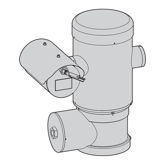
6.5 Preparatory work before 6.5.1 Fixing to parapet or ceiling mount installation Attach the adapter (01) to the bottom of the unit using 4 stainless steel (A4 class 70) socket flat head cap screw M10 x 20mm (02). Use appropriate tools for the installation. The particular nature of the site where the Make sure the thread are free of dirt and debris. -
Page 16: Bracket Mounting
6.5.2 Bracket mounting 6.5.3 Fixing the unit to the pole mount adapter or corner mount adapter The bracket can be fixed to the vertical wall. Use screws and wall fixing devices that can bear at least To install the product on a pole or at a wall corner, four times the weight of the unit. -
Page 17: Fixing With Corner Adapter
6.5.3.2 Fixing with corner adapter 6.5.4 Sunshield mounting Fix the wall bracket to the corner mount adapter Remove the protective film before the using 4 washers, 4 stainless steel grower washers sunshield installation. 4 hexagon stainless steel bolts (A4 class 70) M10x30mm. -
Page 18: Installation
7.2 Methods of installation with local regulations and specifications. The system can be installed only in a standard or VIDEOTEC strongly recommend to test the device inverted position (ceiling mount). When installed configuration and performance before putting it in for inverted operation, the camera orientation and the final installation site (7.3 Connection of the cables... -
Page 19: Connection Of The Cables To The Base
7.3 Connection of the cables to A connection compartment for cable entry with a 3/4” NPT threaded hole is located on the base of the the base unit. A threaded cap gives access to a connection board CAUTION! The electrical system to which the with removable connectors that help the installer to unit is connected must be equipped with a connect the cables. -
Page 20: Connector Board Description
7.4 Connector board description 7.5 Cable entry BOARD DESCRIPTION The telemetry line is not required for normal functioning of the device. Connector/Terminal Function Power supply line To prevent the spread of flames or explosions from Relay, alarms the unit to the conduit system or cable gland to the Serial line external environment, use connection in conformity with IEC/EN60079-14. -
Page 21: Connection Of The Power Supply Line
7.6 Connection of the power All signal cables must be grouped together supply line by means of a cable tie. Depending on the version, the device can be The power cables must be sized according to the provided with different power supply voltages. The ratio between the supply current and the distance to power supply voltage is indicated on the product be covered. -
Page 22: Connection Of The Ethernet Cable
7.7 Connection of the Ethernet 7.8 Alarm and relay connections cable Identify the relay and alarm terminal and the serial line terminal on the board (J3, J9, 7.4 Connector During the wiring do not connect cable RS- board description, page 18). 485 and the video cable. -
Page 23: Connecting An Alarm With Dry Contact
7.8.1 Connecting an alarm with dry 7.8.3 Washing system connection contact For further details on configuration and For a dry contact alarm (alarm AL1), implement the use, refer to the relative manual. connection as shown in the figure. When the washing system is enabled, the relay is used exclusively for the activation of the pump (10.2.9 Wash System Page, page 31). -
Page 24: Connection Compartment Closing
The device could be no longer safe for the installation on a potentially explosive atmosphere. In this case contact VIDEOTEC technical support. The O-ring must be replaced by a new one after each opening. Verify that there is no dirt or debris. -
Page 25: Instructions For Safe Operation
Installation of the electrical equipment must comply before starting the installation. with the local legislation in force. VIDEOTEC strongly recommend to test the device The device must be installed only and exclusively by configuration and performance before putting it in qualified technical personnel. -
Page 26: Switching On
9 Switching on 9.1 Before powering the product in an explosive atmosphere The automatic pre-heating (De-Ice) process could be started whenever the device is Make sure that the unit and other switched on and the ambient temperature components of the installation are closed is below 0°C (+32°F). -
Page 27: Configuration
10 Configuration 10.2.2 Home Page The product control interface is displayed if login is 10.1 Default IP address successful. The Home page displays the snapshot of the camera The unit is configured to obtain an IP and allows you to check the lenses and manage address from a DHCP server. -
Page 28: Horizontal And Vertical Movement
10.2.2.2 Horizontal and vertical movement 10.2.2.4 Day/Night mode control • Day Mode/Auto Mode/Night Mode: The Day The virtual keyboard allows you to move the unit. Use the drop-down menu under the virtual keyboard to Mode inserts the IR filter of the camera. The set the speed. -
Page 29: Home Management
10.2.2.6 Home management • Start Preset Tour: To start a Preset Tour, at least one Preset Tour must be defined and at least • Back to Home/Save Home position/Reset Home one Preset position must be saved. The speed of position: The Home position does not coincide movement and waiting times can be configured on with any Preset. -
Page 30: Camera Settings Page
10.2.4 Camera Settings Page • White Balance: Configuration parameters. • Mode: It allows configuring the white balance in On the menu item, it is possible to set the camera automatic or manual. When manual mode is set, parameters. intensity can be adjusted of the primary colours Some fields are displayed dynamically, depending on red and blue. -
Page 31: Network Page
• Options: Configuration parameters. From the same page it is possible to configure 2 DNS and decide which mechanisms must be enabled • Saturation: The parameter sets the fullness to automatically identify the devices in the local value of the colours of the image. network. -
Page 32: Users Page
10.2.6 Users Page 10.2.7 Motions Recall Page On the menu item, the users who can access the In the Motions Recall menu item, you can specify the device can be administered. time intervals after which the product will execute certain functions. Administrator type users can access the complete •... -
Page 33: Video Analysis Page
10.2.8 Video Analysis Page 10.2.10 Movement Parameters page The device can be configured to emit motion From menu entry Movement Parameters it is possible detection alarms using ONVIF events. to control, via web, all Pan & Tilt parameters. • Options This page allows you to define the following settings: •... -
Page 34: Preset Tour Page
10.2.11 Preset Tour Page • Movement Limits • Pan Limits: Enables the limits of Pan. On the menu item, it is possible to define and set parameters for the Preset Tour and Preset. • Pan Start: Sets the start limit of Pan. For this version of the device, a single Preset Tour •... -
Page 35: Directional Osd Page
10.2.12 Directional OSD Page The device supports definition of four pan regions and information text video display based on the position of the Pan & Tilt. You can define the following settings for each area: • Enabled: Each area can be configured as disabled, enabled clockwise and enabled anti-clockwise. -
Page 36: Digital I/O Page
10.2.14 Digital I/O Page 10.2.15 Device Statistics page From menu entry Digital I/O it is possible to configure From menu entry Device Statistics all of the statistics the Digital Input and Output channels available in the are gathered during device operation are provided in device. -
Page 37: Instructions For Normal Operation
11 Instructions for normal 11.1 Special controls operation SPECIAL CONTROLS Action Command Do not use the wiper if the outside Protocol temperature is below 0°C or in case of ice. HTTP API ONVIF (auxiliary command) If it is left on, the wiper automatically √1 Wiper Start tt:Wiper|On... -
Page 38: Maintenance
For damage to any parts, repair or replacement must be done by, or under supervision of VIDEOTEC. Whenever replacing the parts as indicated, always use VIDEOTEC original spare parts and meticulously follow the maintenance instructions supplied with every spare parts kit. -
Page 39: Factory Default
12.2.2 Factory Default • Power the unit. • Wait 30 seconds. Before doing any technical work or • Open the previously closed contact. maintenance on the device, make sure that potentially explosive atmosphere is not • Wait for 2 minutes. present. -
Page 40: Information On Disposal And Recycling
This product must only be repaired by suitably trained personnel or under the The European Directive 2012/19/EU on Waste supervision of VIDEOTEC personnel in Electrical and Electronic Equipment (WEEE) mandates accordance with the foreseen terms and that these devices should not be disposed of in the conditions: IEC/EN60079-19. -
Page 41: Technical Data
16 Technical data 16.4 Network Ethernet connection: 100 Base-TX 16.1 General Connector: RJ45 AISI 316L stainless steel construction 16.5 Video Passivated and electropolished external surfaces Video encoder Dynamic positioning control system • Communication protocol: ONVIF, Profile S and 16.2 Mechanical Profile Q 1 3/4"... -
Page 42: Cameras
16.7 Cameras 16.8 Environment Day/Night Full HD 30x For installation indoors and outdoors Resolution: Full HD 1080p (1920x1080pixel) Operating temperature: from -40°C (-40°F) up to +60°C (140°F) Image Device: 1/2.8" Exmor™ R CMOS sensor Relative humidity: from 10% up to 95% (no Effective Pixels: approx. -
Page 43: Electrical Rating
16.10 Electrical rating ELECTRICAL RATING Supply voltage Normal usage to be specified on product label Short term de-icing cicle. Peak maintaining a minimum internal temp at 5°C 230Vac 0.11A, 50/60Hz, 25.3W 0.52A, 50/60Hz, 120W 24Vac 1.08A, 50/60Hz, 25.9W 5A, 50/60Hz, 120W 120Vac 0.21A, 50/60Hz, 25.2W 1A, 50/60Hz, 120W... -
Page 44: A Appendix - Marking Codes
EN - English - Instruction manual A Appendix - Marking codes A.1 ATEX marking 2 G Ex db ÐÐC T6 Gb T -40°C to +60°C ÏÐÐ ÐÐ 2 D Ex tb ÐÐÐC T85°C Db T -40°C to +60°C Ï IP66 Fig. -
Page 45: A.2 Iecex Marking
A.2 IECEx marking Ex db eeC T6 Gb T -40°C to +60°C Ex tb eeeC T85°C Db T -40°C to +60°C IP66 Fig. 51 Ex db ÐÐC Tfi -40°C to +60°C Ex-proof housing for potentially Gas group Gas temperature classification Protection level of the equipment Installation temperature range explosive environments... -
Page 46: A.3 Gas Group Classification
A.3 Gas group classification The table below shows the classification of some gases and vapours, according to the explosion-proof protection group and the temperature class. For a complete list see IEC/EN60079-12 and IEC/EN60079-20. GAS GROUP CLASSIFICATION Temperature class (Maximum surface temperature of the housing) 1 Class 450°C (842°F) 300°C (572°F) -
Page 47: B Appendix - Flamepath
B Appendix - Flamepath The maximum constructional gap (ic) is less than that required by Table 3 of EN 60079-1:2014 as detailed below: FLAMEPATH MAXIMUM GAP (MM) MINIMUM WIDTH (MM) COMMENT Between component drawings 0.249 25.4 Cylindrical joint sup- BRT2MPXALBPAN-EX e BRT2MPXTAPINF-EX ported by bearings Between component drawings 0.245... - Page 48 Email: info@videotec.com Tel. +33 1 60491816 - Fax +33 1 69284736 Email: info.fr@videotec.com Asia Pacific Videotec (HK) Ltd Americas Videotec Security, Inc. Flat 8, 19/F. On Dak Industrial Building, No. 2-6 Wah Sing Street Gateway Industrial Park, 35 Gateway Drive, Suite 100 Kwai Chung, New Territories - Hong Kong Plattsburgh, NY 12901 - U.S.A.
- Page 49 ITALIANO MAXIMUS MPXHD DELUX Telecamera PTZ Full HD antideflagrante con nuova tecnologia DELUX, visione day/night con straordinaria luminosità notturna Italiano - Manuale di istruzioni...
- Page 51 Sommario I T A L I A N O 1 Informazioni sul presente manuale ..................7 1.1 Convenzioni tipografiche ..............................7 2 Note sul copyright e informazioni sui marchi commerciali ..........7 3 Nota sulla sicurezza dei dati ....................7 3.1 Introduzione ...................................
- Page 52 8.1.2 Prescrizioni di sicurezza ..................................23 8.1.3 Prescrizioni di prevenzione delle esplosioni ..........................23 9 Accensione ..........................24 9.1 Prima di alimentare il prodotto in atmosfera esplosiva ..................24 10 Configurazione ........................25 10.1 Indirizzo IP di default ..............................25 10.2 Interfaccia web .................................25 10.2.1 Primo accesso alle pagine web..............................
- Page 53 16.2 Meccanica ...................................39 16.3 Elettrico ....................................39 16.4 Rete .......................................39 16.5 Video .....................................39 16.6 Interfaccia I/O ..................................39 16.7 Telecamere..................................40 16.8 Ambiente ....................................40 16.9 Certificazioni ..................................40 16.10 Consumo elettrico .................................41 17 Disegni tecnici ........................41 A Appendice - Codifica della marcatura................. 42 A.1 Marcatura ATEX ...................................42 A.2 Marcatura IECEx ..................................43 A.3 Classificazione Gruppi Gas ..............................44...
- Page 54 MNVCMPXHDB_1822_IT...
-
Page 55: Informazioni Sul Presente Manuale
PERICOLO! un impianto di videosorveglianza all’interno del quale Pericolosità elevata. sono installati ed integrati i prodotti VIDEOTEC S.p.A.. Rischio di scosse elettriche. Prima di L’eterogeneità degli scenari applicativi impedisce eseguire qualsiasi operazione assicurarsi di... -
Page 56: Funzionalità Di Sicurezza Attivabili Nel Prodotto
Data la tipologia di contesti tecnici all’interno dei di permettere l’installazione del prodotto anche quali i dispositivi di VIDEOTEC S.p.A. vengono in condizioni ambientali particolari o difficili, o di tipicamente utilizzati, non è possibile, né sarebbe... -
Page 57: Norme Di Sicurezza
4 Norme di sicurezza • Attenersi a tutte le istruzioni. • Per ridurre il rischio di innesco, non aprire o scollegare l’apparecchio in presenza di ATTENZIONE! L’apparecchio deve essere un’atmosfera potenzialmente esplosiva. Mantenere collegato a un conduttore di terra (messa il prodotto chiuso durante l’utilizzo. -
Page 58: Identificazione
5 Identificazione • L’apparecchio è controllato a distanza e può pertanto cambiare posizione in qualsiasi momento. Installare l’apparecchio in modo da 5.1 Descrizione e designazione evitare incidenti causati dal contatto con parti del prodotto in movimento, facendo sì che queste non urtino contro altri oggetti creando situazioni pericolose. -
Page 59: Marcatura Del Prodotto
5.2 Marcatura del prodotto Fig. 2 Simbolo CE 10. Certificazione ATEX: Nome e indirizzo del costruttore • Numero di certificato ATEX Codice di identificazione del modello • Classificazione del tipo di zona, metodo di protezione, classe di temperatura per le quali è Temperatura ambiente di utilizzo riferita al ammesso l’impiego di questo prodotto secondo codice di identificazione del modello... -
Page 60: Preparazione Del Prodotto Per L'utilizzo
6 Preparazione del prodotto Effettuare i collegamenti e prove in per l'utilizzo laboratorio prima dell’installazione nel sito. Utilizzare degli utensili adeguati. Qualsiasi intervento non espressamente Prima di effettuare qualsiasi operazione, approvato dal costruttore fa decadere la assicurarsi che la tensione della linea sia garanzia e la certificazione. -
Page 61: Lavoro Preparatorio Prima Dell'installazione
6.5 Lavoro preparatorio prima 6.5.1 Fissaggio a parapetto o a soffitto dell’installazione Collegare l’adattatore (01) al fondo dell’unità utilizzando 4 viti a testa svasata piana (02) con esagono incassato M10x20mm in acciaio inox (A4 Eseguire l’installazione utilizzando utensili classe 70). adeguati. -
Page 62: Fissaggio Con Staffa
6.5.2 Fissaggio con staffa 6.5.3 Fissaggio con imbracatura da palo o modulo adattatore angolare Il supporto può essere fissato direttamente ad un muro verticale. Utilizzare viti e dispositivi di fissaggio Per installare il prodotto su imbracatura da palo o in a muro che possono sostenere un peso almeno 4 corrispondenza di un angolo prima di tutto fissare volte superiore a quello dell’unità. -
Page 63: Fissaggio Con Modulo Angolare
6.5.3.2 Fissaggio con modulo angolare 6.5.4 Fissaggio del tettuccio Per fissare la staffa di supporto a muro al modulo Prima di fissare il tettuccio della custodia adattatore angolare, utilizzare 4 rondelle piane, rimuovere la pellicola protettiva. 4 rondelle grower in acciaio inox e 4 viti a testa esagonale in acciaio inox (A4 classe 70) da Fissare il tettuccio alla custodia utilizzando viti e M10x30mm. -
Page 64: Installazione
L'unità può essere installata solamente in posizione standard o invertita (montaggio a VIDEOTEC raccomanda di testare la configurazione e soffitto). Se installata in quest’ultima posizione, la le prestazioni dell’apparecchio prima di collocarlo nel riconfigurazione delle funzioni di orientamento sito di installazione definitivo (7.3 Collegamento dei... -
Page 65: Collegamento Dei Cavi Alla Base
7.3 Collegamento dei cavi alla Sulla base dell’unità è presente un vano connessioni con foro filettato da 3/4” NPT per l’ingresso dei cavi. base Svitando il coperchio filettato si accede a una scheda di connettori dotata di connettori rimovibili ATTENZIONE! L’impianto elettrico al quale che facilitano il collegamento dei cavi durante è... -
Page 66: Descrizione Della Scheda Connettori
7.4 Descrizione della scheda 7.5 Ingresso cavi connettori La linea di telemetria non è necessaria per il normale funzionamento del dispositivo. DESCRIZIONE DELLA SCHEDA Connettore/Morsetto Funzione Per prevenire la propagazione di fiamme o esplosioni dal dispositivo al sistema conduit o pressacavo, e Linea di alimentazione da quest’ultimi all’ambiente esterno, eseguire una Relè, allarmi... -
Page 67: Collegamento Della Linea Di Alimentazione
7.6 Collegamento della linea di Tutti i cavi di segnale devono essere alimentazione raggruppati con una fascetta. A seconda della versione, al dispositivo possono I cavi di alimentazione dovranno essere dimensionati essere fornite diverse tensioni di alimentazione. in base al rapporto tra la corrente di alimentazione e Il valore di tensione di alimentazione è... -
Page 68: Collegamento Del Cavo Di Rete Ethernet
7.7 Collegamento del cavo di rete 7.8 Collegamento degli allarmi e Ethernet dei relè Individuare sulla scheda il morsetto dei relè e allarmi Durante le operazioni di cablaggio non e il morsetto della linea seriale (J3, J9, 7.4 Descrizione collegare il cavo RS-485 e il cavo video. della scheda connettori, pagina 18). -
Page 69: Collegamento Allarme Con Contatto Pulito
7.8.1 Collegamento allarme con 7.8.3 Collegamento dell'impianto di contatto pulito lavaggio Nel caso di allarme a contatto pulito (allarme AL1), Per ulteriori dettagli sulla configurazione eseguire il collegamento come illustrato in figura. e l’utilizzo fare riferimento al manuale del relativo accessorio. Quando l'impianto di lavaggio viene abilitato, il relè... -
Page 70: Chiusura Del Vano Connessioni
In questo caso rivolgersi al servizio tecnico di VIDEOTEC. Ad ogni apertura l'O-ring deve essere sostituito con uno nuovo. Verificare che non vi sia la presenza di sporcizia o residui. -
Page 71: Istruzioni Di Funzionamento In Sicurezza
L’installazione dell’apparecchio deve essere eseguita manuale d’uso prima di procedere con l’installazione. esclusivamente da personale specializzato. VIDEOTEC raccomanda di testare la configurazione e le prestazioni dell’apparecchio prima di collocarlo nel 8.1.3 Prescrizioni di prevenzione delle sito di installazione definitivo. Utilizzare degli utensili esplosioni adeguati. -
Page 72: Accensione
9 Accensione 9.1 Prima di alimentare il prodotto in atmosfera esplosiva La procedura di preriscaldamento automatico (De-Ice) si potrebbe attivare Assicurarsi che l'unità e gli altri componenti tutte le volte che il dispositivo viene acceso dell’impianto siano chiusi in modo idoneo a ad una temperatura ambiente inferiore impedire il contatto con componenti sotto a 0°C. -
Page 73: Configurazione
10 Configurazione 10.2.2 Pagina Home Se il login viene effettuato con successo, verrà 10.1 Indirizzo IP di default mostrata l'interfaccia di gestione del prodotto. Nella pagina Home è possibile visualizzare lo L'unità è configurata per ottenere l'indirizzo snapshot della telecamera, controllarne le ottiche e IP da un server DHCP. -
Page 74: Movimento Orizzontale E Verticale
10.2.2.2 Movimento orizzontale e verticale 10.2.2.4 Controllo della modalità Diurna/ Notturna La tastiera virtuale permette di muovere l'unità. Per impostare la velocità utilizzare il menù presente sotto • Modalità Diurna/Modalità Automatica/Modalità la tastiera virtuale. Notturna: La Modalità Diurna inserisce il filtro IR della telecamera. -
Page 75: Gestione Home
10.2.2.6 Gestione Home • Attiva Preset Tour: Per attivare un Preset Tour deve essere stato definito almeno un Preset Tour • Torna alla Home/Salva posizione Home/Reset e deve essere salvata almeno una posizione di posizione Home: La posizione di Home non Preset. -
Page 76: Pagina Impostazioni Telecamera
10.2.4 Pagina Impostazioni Telecamera • Bilanciamento Bianco: Parametri di configurazione. Alla voce del menù è possibile impostare i parametri • Modalità: Permette di configurare il della telecamera. bilanciamento del bianco in modalità La visualizzazione di alcuni campi avviene in maniera automatica o manuale. -
Page 77: Pagina Rete
• Opzioni: Parametri di configurazione. Nella stessa pagina è possibile configurare 2 DNS e decidere quali meccanismi debbano essere attivi per • Saturazione: Il parametro imposta il valore di identificare automaticamente i dispositivi nella rete pienezza dei colori dell'immagine. locale. •... -
Page 78: Pagina Utenti
10.2.6 Pagina Utenti 10.2.7 Pagina Richiamo Movimenti Alla voce del menù è possibile amministrare gli utenti Alla voce del menù Richiamo Movimenti è possibile che possono accedere al dispositivo. specificare gli intervalli temporali dopo i quali il prodotto provvederà ad eseguire determinate Gli utenti di tipo Administrator possono accedere alla funzioni. -
Page 79: Pagina Analisi Video
10.2.8 Pagina Analisi Video 10.2.10 Pagina Parametri Movimento Il dispositivo può essere configurato affinché emetta Alla voce del menù Parametri Movimento è possibile degli allarmi di motion detection mediante eventi controllare via web tutti i parametri del brandeggio. ONVIF. • Opzioni In questa pagina è... -
Page 80: Pagina Preset Tour
10.2.11 Pagina Preset Tour • Limiti di Movimento • Limiti Pan: Abilita i limiti del Pan. Alla voce del menù è possibile definire e parametrizzare i Preset Tour e i Preset. • Pan Inizio: Imposta il limite iniziale del Pan. Per questa versione del dispositivo, è... -
Page 81: Pagina Osd Direzionale
10.2.12 Pagina OSD Direzionale Il dispositivo supporta la definizione di quattro regioni pan e la visualizzazione a video di testo informativo in base alla posizione del brandeggio. È possibile definire per ogni area i seguenti parametri: • Attiva: Ogni area può essere configurata come inattiva, attiva in senso orario ed attiva in senso antiorario. -
Page 82: Pagina I/O Digitali
10.2.14 Pagina I/O Digitali 10.2.15 Pagina Statistiche Dispositivo Alla voce del menù I/O Digitali è possibile configurare Alla voce del menù Statistiche Dispositivo sono gli Ingressi e le Uscite Digitali del dispositivo. riportate, per la sola consultazione, tutte le statistiche raccolte durante il funzionamento del dispositivo. -
Page 83: Istruzioni Di Funzionamento Ordinario
• Tramite il software PTZ Assistant (fare riferimento al manuale del prodotto). √1 Autofocus tt:Autofocus|On Relé On – tt:Relay1|On Relé Off – tt:Relay1|Off Tab. 5 1 Comando attivabile, per ulteriori informazioni contat- tare il centro di assistenza VIDEOTEC. MNVCMPXHDB_1822_IT... -
Page 84: Manutenzione
T 4A H 250V 5x20 EN60079-19. Tab. 6 In caso di danneggiamento la sostituzione o riparazione delle parti interessate deve essere eseguita da VIDEOTEC o sotto la sua supervisione. Come indicato, qualsiasi sostituzione di ricambi, deve essere eseguita utilizzando solamente ricambi originali VIDEOTEC,... -
Page 85: Factory Default
12.2.2 Factory Default • Alimentare l'unità. • Attendere 30 secondi. Prima di effettuare interventi tecnici • Aprire il contatto chiuso in precedenza. sull’apparecchio, assicurarsi che non sia presente atmosfera potenzialmente • Attendere 2 minuti. esplosiva. • Spegnere l'unità. • Alimentare l'unità. Se la password di accesso non è... -
Page 86: Informazioni Sullo Smaltimento E Il Riciclo
La Direttiva Europea 2012/19/UE sui Rifiuti di adeguatamente addestrato o con la Apparecchiature Elettriche ed Elettroniche (RAEE) supervisione del personale VIDEOTEC prevede che questi apparecchi non debbano essere in conformità alla norme previste: IEC/ smaltiti nel normale flusso dei rifiuti solidi urbani, ma EN60079-19. -
Page 87: Dati Tecnici
16 Dati tecnici 16.4 Rete Connessione Ethernet: 100 Base-TX 16.1 Generale Connettore: RJ45 Costruzione in acciaio Inox AISI 316L 16.5 Video Superfici esterne passivate ed elettrolucidate Encoder video Sistema dinamico di controllo della posizione • Protocollo di comunicazione: ONVIF, Profilo S e 16.2 Meccanica Profilo Q 1 foro 3/4"... -
Page 88: Telecamere
16.7 Telecamere 16.8 Ambiente Day/Night Full HD 30x Installazione per interni ed esterni Risoluzione: Full HD 1080p (1920x1080pixel) Temperatura di esercizio: da -40°C fino a +60°C Sensore di immagine: 1/2.8" Exmor™ R CMOS sensor Umidità relativa: da 10% fino a 95% (senza condensa) Pixel Effettivi: appross. -
Page 89: Consumo Elettrico
16.10 Consumo elettrico CONSUMO ELETTRICO Tensione di Normale utilizzo da specificare nella targhetta di Massimo consumo durante la procedura di preriscal- alimentazione marcatura damento automatico (De-Ice) per mantenere una temperatura minima interna 5°C 230Vac 0.11A, 50/60Hz, 25.3W 0.52A, 50/60Hz, 120W 24Vac 1.08A, 50/60Hz, 25.9W 5A, 50/60Hz, 120W... -
Page 90: A Appendice - Codifica Della Marcatura
IT - Italiano - Manuale di istruzioni A Appendice - Codifica della marcatura A.1 Marcatura ATEX 2 G Ex db ÐÐC T6 Gb T -40°C to +60°C ÏÐÐ ÐÐ 2 D Ex tb ÐÐÐC T85°C Db T -40°C to +60°C Ï... -
Page 91: A.2 Marcatura Iecex
A.2 Marcatura IECEx Ex db eeC T6 Gb T -40°C to +60°C Ex tb eeeC T85°C Db T -40°C to +60°C IP66 Fig. 51 Ex db ÐÐC Tfi -40°C to +60°C Custodia antideflagrante per am- Gruppo gas Classificazione di temperatura Livello di protezione dell'apparec- Range di temperatura di installazione bienti potenzialmente esplosivi... -
Page 92: A.3 Classificazione Gruppi Gas
A.3 Classificazione Gruppi Gas La tabella di seguito mostra la classificazione di alcuni gas e vapori in base ai gruppi di protezione antideflagrante ed alle temperature. Per una lista completa fare riferimento alla IEC/EN60079-12 e alla IEC/ EN60079-20. CLASSIFICAZIONE GRUPPI GAS Classe di temperatura (Massima temperatura superficiale °C della custodia) 1 Classe 450°C... -
Page 93: B Appendice - Percorso Di Fiamma
B Appendice - Percorso di fiamma Il gap costruttivo massimo (ic) è minore di quanto richiesto dalla Tabella 3 della EN 60079-1:2014, come indicato sotto: DIVARIO MASSIMO LUNGHEZZA MINIMA PERCORSO DI FIAMMA COMMENTO (MM) (MM) Tra componenti del disegno 0.249 25.4 Giunto cilindrico soste- BRT2MPXALBPAN-EX e BRT2MPXTAPINF-EX... - Page 94 Email: info@videotec.com Tel. +33 1 60491816 - Fax +33 1 69284736 Email: info.fr@videotec.com Asia Pacific Videotec (HK) Ltd Americas Videotec Security, Inc. Flat 8, 19/F. On Dak Industrial Building, No. 2-6 Wah Sing Street Gateway Industrial Park, 35 Gateway Drive, Suite 100 Kwai Chung, New Territories - Hong Kong Plattsburgh, NY 12901 - U.S.A.
- Page 95 FRANÇAIS MAXIMUS MPXHD DELUX Caméra PTZ Full HD antidéflagration avec la nouvelle technologie DELUX, vision jour/nuit pour une extraordinaire luminosité nocturne Français - Manuel d’instructions...
- Page 97 Sommaire F R A N Ç A I S 1 À propos de ce mode d’emploi ....................7 1.1 Conventions typographiques ............................7 2 Notes sur le copyright et informations sur les marques de commerce ......7 3 Note sur la sécurité des données ................... 7 3.1 Introduction ...................................
- Page 98 8.1.2 Précautions de sécurité..................................23 8.1.3 Précautions contre les explosions ..............................23 9 Allumage ..........................24 9.1 Avant d'alimenter le produit en atmosphère explosive ..................24 10 Configuration ........................25 10.1 Adresse IP par défaut ..............................25 10.2 Interface web ..................................25 10.2.1 Premier accès aux pages web ..............................25 10.2.2 Page Home......................................
- Page 99 16.2 Mécanique ..................................39 16.3 Électrique ....................................39 16.4 Réseau ....................................39 16.5 Vidéo .....................................39 16.6 Interface I/O ..................................39 16.7 Caméras ....................................40 16.8 Environnement .................................40 16.9 Certifications ..................................40 16.10 Consommation électrique ............................41 17 Dessins techniques ......................41 A Annexe - Codification du marquage ................... 42 A.1 Marquage ATEX ..................................42 A.2 Marquage IECEX .................................43 A.3 Classification groupes gaz ..............................44...
- Page 100 MNVCMPXHDB_1822_FR...
-
Page 101: Propos De Ce Mode D'emploi
Avant d'installer et d'utiliser cette unité, lire 3.1 Introduction attentivement toute la documentation fournie. Garder le manuel à portée de main pour des VIDEOTEC S.p.A. fabrique des produits destinés consultations successives. à la vidéosurveillance, exclusivement à usage professionnel. Les produits VIDEOTEC S.p.A. peuvent 1.1 Conventions typographiques... -
Page 102: Fonctions De Sécurité Activables Sur Le Produit
3.2.1 Identifiants d'authentification • Activer certaines ou toutes les fonctions de Le produit propose deux modes de fonctionnement : sécurité proposées par le dispositif de VIDEOTEC FactoryDefaultState et OperationalState. Lors de S.p.A. ; la première utilisation, le dispositif est en mode •... -
Page 103: Normes De Securité
4 Normes de securité • Respecter toutes les instructions. • Pour réduire le risque d'allumage, ne pas ouvrir ou débrancher l'appareil dans une atmosphère ATTENTION! L’appareil doit être branché potentiellement explosive. Garder le produit fermé à un conducteur de terre (mise à terre pendant l'utilisation. -
Page 104: Identification
5 Identification • L’appareil est contrôlé à distance et peut donc changer de position à tout moment. Installer l'appareil de façon à éviter les accidents causés 5.1 Description et désignation du par le contact avec des parties en mouvement, produit en faisant en sorte que ces parties ne se heurtent pas à... -
Page 105: Marquage Du Produit
5.2 Marquage du produit Fig. 2 Symbole CE 10. Certification ATEX: Nom et adresse du fabricant • Numéro de certificat ATEX Code d'identification du modèle • Classement du type de zone, de la méthode de protection, de la classe de température pour Température ambiante d'utilisation se référant lesquels l'emploi de ce produit est permis selon au code d'identification du modèle... -
Page 106: Préparation Du Produit En Vue De L'utilisation
6 Préparation du produit en Effectuer les branchements et les essais en vue de l’utilisation atelier avant l’installation sur site. Utiliser des outils adéquats. Tout changement non expressément Avant d'effectuer toute opération, s'assurer approuvé par le fabricant annule la garantie que la tension de la ligne soit correcte. -
Page 107: Opérations À Effectuer Avant L'installation
6.5 Opérations à effectuer avant 6.5.1 Fixation sur parapet ou plafond l’installation Brancher l'adaptateur (01) au fond de l'unité en utilisant 4 vis à tête plate évasée (02) avec hexagone encastré M10x20mm en acier inox (A4 classe 70). Effectuer l'installation en utilisant des outils adéquats. -
Page 108: Fixation Avec Étrier
6.5.2 Fixation avec étrier 6.5.3 Fixation avec poteau ou module adaptateur angulaire Le support peut être fixé directement sur un mur vertical. Utiliser des vis et des dispositifs de fixation Pour installer le produit sur la fixation pour poteau ou murale pouvant soutenir un poids au moins 4 fois face à... -
Page 109: Fixation Avec Module Angulaire
6.5.3.2 Fixation avec module angulaire 6.5.4 Fixation du double toit Pour fixer l'étrier de support mural au module Avant de fixer le toit du caisson, enlever le adaptateur angulaire, utiliser 4 rondelles pleines, film de protection. 4 rondelles élastiques en acier inox et 4 vis à tête hexagonale en acier inox (A4 classe 70) de Fixer le double toit au caisson en utilisant des vis et M10x30mm. -
Page 110: Installation
(montage au plafond). Si elle est installée dans cette dernière position, la VIDEOTEC conseille de tester la configuration et les reconfiguration des fonctions d'orientation et de performances de l'appareils avant de placer celui-ci contrôle de la caméra a lieu à l'aide du logiciel de sur le lieu d'installation définitive (7.3 Connexion des... -
Page 111: Connexion Des Câbles À La Base
7.3 Connexion des câbles à la Selon l'unité, on trouve un compartiment des connexions avec trou taraudé 3/4” NPT pour l'entrée base des câbles. En dévissant le bouchon taraudé, on a accès à une ATTENTION! Le circuit électrique auquel carte de connecteurs équipée de connecteurs l'unité... -
Page 112: Description De La Carte De Connexion
7.4 Description de la carte de 7.5 Entrée câbles connexion La ligne de télémétrie n'est pas nécessaire pour le fonctionnement normal du DESCRIPTION DE LA CARTE dispositif. Connecteur/Borne Fonction Pour prévenir la propagation de flammes ou Ligne d'alimentation explosions du dispositif vers le système conduit ou Relais, alarmes presse-étoupe, et de ceux-ci vers le milieu extérieur, Ligne serielle... -
Page 113: Connexion De La Ligne D'alimentation
7.6 Connexion de la ligne Tous les câbles de signalisation doivent d'alimentation également être regroupés avec un collier. Selon la version, différentes tensions d'alimentation Les câbles d'alimentation devront être dimensionnés peuvent être fournies au dispositif. La valeur de en fonction du rapport entre le courant tension d'alimentation est reportée sur l'étiquette d'alimentation et la distance à... -
Page 114: Branchement Du Câble De Réseau Ethernet
7.7 Branchement du câble de 7.8 Branchement aux alarmes et réseau Ethernet aux relais Identifier sur la carte la borne des relais et des Pendant le câblage ne pas brancher le câble alarmes et la borne de la ligne sérielle (J3, J9, 7.4 RS-485 et le câble vidéo. -
Page 115: Branchement D'alarme Avec Contact Sec
7.8.1 Branchement d’alarme avec 7.8.3 Branchement du système de contact sec lavage En cas d’alarme avec contact sec (alarme AL1), Pour de plus amples informations sur la effectuer le branchement comme illustré sur la figure. configuration et l'utilisation, consulter le manuel de l'accessoire correspondant. -
Page 116: Fermeture Du Compartiment Des Connexions
L'appareil pourrait ne plus être adapté à une installation sûre dans une atmosphère potentiellement explosive. Dans ce cas, s'adresser au service technique de VIDEOTEC. À chaque ouverture l'O-ring doit être remplacé par un neuf. Vérifier l'absence de saleté ou de résidus. -
Page 117: Instructions De Sécurité Concernant Le Fonctionnement
à l'installation. 8.1.3 Précautions contre les explosions VIDEOTEC conseille de tester la configuration et les Utiliser des outils adaptés à la zone dans laquelle on performances de l'appareils avant de placer celui-ci travaille. -
Page 118: Allumage
9 Allumage 9.1 Avant d'alimenter le produit en atmosphère explosive La procédure de préchauffage automatique (De-Ice) peut être activée chaque fois S'assurer que l'unité et les autres que le dispositif est mis en fonction à composants de l'installation soient fermés une température ambiante inférieure de façon à... -
Page 119: Configuration
10 Configuration 10.2.2 Page Home Si le login est effectué avec succès, on pourra voir 10.1 Adresse IP par défaut l'interface de gestion de le produit. Sur la page d'accueil (Home), il est possible d'afficher L’appareil est configuré pour obtenir l'instantané... -
Page 120: Mouvement Horizontal Et Vertical
10.2.2.2 Mouvement horizontal et vertical 10.2.2.4 Contrôle du mode Jour/Nuit • Modalité Jour/Modalité Automatique/Modalité Le clavier virtuel permet de déplacer l’appareil. Pour définir la vitesse, utilisez le menu déroulant présent Nuit: La Modalité Jour insère le filtre IR de la sous le clavier virtuel. -
Page 121: Gestion Home
10.2.2.6 Gestion Home • Début Preset Tour: Pour activer un Preset Tour, il faut avoir défini au moins un Preset Tour et • Revenir à la page d'accueil/Enregistrer enregistré au moins une position de Preset. Les position Page d'accueil/Réinitialiser position vitesses de mouvement et les temps d’attente Page d'accueil: La position Home ne coïncide peuvent être configurés dans la page Preset Tour. -
Page 122: Page Programmations Caméra
10.2.4 Page Programmations Caméra • Équilibre Blanc: Paramètres de configuration. • Mode: Cela permet de configurer la balance du À la rubrique du menu, il est possible de programmer blanc en mode automatique ou manuel. Quand les paramètres de la caméra. on est en modalité... -
Page 123: Page Réseau
• Options: Paramètres de configuration. Toujours sur la même page, il est possible de configurer 2 DNS et de décider quels mécanismes • Saturation: Le paramètre programme la valeur doivent être actifs pour identifier automatiquement d'intensité des couleurs de l'image. les dispositifs dans le réseau local. -
Page 124: Page Utilisateurs
10.2.6 Page Utilisateurs 10.2.7 Page Rappel Mouvements À la rubrique du menu, il est possible d'administrer À l'entrée du menu Rappel Mouvements, vous les utilisateurs qui peuvent accéder au dispositif. pouvez spécifier les intervalles de temps après lesquels le produit exécutera des fonctions Les utilisateurs de type Administrateur peuvent déterminées. -
Page 125: Page Analyses Vidéo
10.2.8 Page Analyses Vidéo 10.2.10 Page Paramètres Mouvement Le dispositif peut être configuré pour émettre A la mention du menu Paramètres Mouvement il est des alarmes de détection de mouvement par possible de contrôler par web tous les paramètres de l'intermédiaire d'événements ONVIF. -
Page 126: Page Preset Tour
10.2.11 Page Preset Tour • Limites de Mouvement • Limites Pan: Valide les limites de Pan. À la rubrique du menu, il est possible de définir et de paramétrer les Presets Tour et les Presets. • Pan Début: Configure la limite initiale de Pan. Pour cette version du dispositif, un seul Preset Tour •... -
Page 127: Page Osd Directionnelle
10.2.12 Page OSD Directionnelle Le dispositif supporte la définition de quatre régions de rotation (pan) et l'affichage vidéo d'un texte d'information en fonction de la position de la tourelle. Il est possible de définir pour chaque aire les paramètres suivants: •... -
Page 128: Page I/O Digitaux
10.2.14 Page I/O Digitaux 10.2.15 Page Statistiques Dispositif À la rubrique du menu I/O numériques, il est possible A la mention du menu Statistiques Dispositif on de configurer les Entrées et les Sorties Numériques trouve, uniquement pour consultation, toutes les du dispositif. -
Page 129: Instructions De Fonctionnement Courant
11 Instructions de 11.1 Commandes spéciales fonctionnement courant COMMANDES SPÉCIALES Action Commande Ne pas utiliser l’essuie-glace avec Protocole température extérieure inférieure à 0°C ou HTTP API ONVIF (auxiliary en cas de givre. command) √1 Wiper Start tt:Wiper|On L’essuie-glace est exclu de façon automatique si on le laisse allumé. -
Page 130: Entretien
Nous conseillons, pour n'importe quelle intervention de maintenance, de rapporter le produit en laboratoire pour effectuer les opérations nécessaires. Lorsque vous contactez le service technique de VIDEOTEC, il est nécessaire de fournir le numéro de série et le code d'identification du modèle. MNVCMPXHDB_1822_FR... -
Page 131: Factory Default
12.2.2 Factory Default • Allumer l'unité. • Attendre 30 secondes. Avant d'effectuer des interventions • Ouvrir le contact fermé précédemment. techniques sur l'appareil, s'assurer qu'il n'y ait pas d'atmosphère potentiellement • Attendre 2 minutes. explosive. • Éteindre l'unité. • Allumer l'unité. Si le mot de passe d'accès n'est plus disponible, il est possible de rétablir les Une fois la procédure de standard usine... -
Page 132: Informations Sur L'élimination Et Le Recyclage
La Directive Européenne 2012/19/UE sur les déchets formé ou sous la supervision du personnel d'équipements électriques et électroniques (DEEE) VIDEOTEC conformément aux normes exige que ces dispositifs ne doivent pas être éliminés prévues: IEC/EN60079-19. dans le flux normal de déchets solides municipaux, mais ils doivent être collectés séparément afin... -
Page 133: Données Techniques
16 Données techniques 16.4 Réseau Connexion Ethernet: 100 Base-TX 16.1 Généralités Connecteur: RJ45 Construction en acier inox AISI 316L 16.5 Vidéo Surfaces externes passivées et électropolies Encodeur vidéo Système dynamique de contrôle de la position • Protocole de communication: ONVIF, Profil S et 16.2 Mécanique Profil Q 1 trou 3/4"... -
Page 134: Caméras
16.7 Caméras 16.8 Environnement Day/Night Full HD 30x Installation d'intérieur et d'extérieur Résolution: Full HD 1080p (1920x1080pixel) Température de fonctionnement: de -40°C jusqu'à +60°C Capteur d'image: 1/2.8" Exmor™ R CMOS sensor Humidité relative: de 10% jusqu'à 95% (sans Pixels effectifs: environ 2.38 Megapixels condensation) Éclairage minimum: 16.9 Certifications... -
Page 135: Consommation Électrique
16.10 Consommation électrique CONSOMMATION ÉLECTRIQUE Tension d’ali- Utilisation normale à indiquer dans la plaquette de Consommation plus grande pendant la procédure de mentation marquage préchauffage automatique (De-Ice) pour garder une température interne minimale de 5°C 230Vac 0.11A, 50/60Hz, 25.3W 0.52A, 50/60Hz, 120W 24Vac 1.08A, 50/60Hz, 25.9W 5A, 50/60Hz, 120W... -
Page 136: A Annexe - Codification Du Marquage
FR - Français - Manuel d’instructions A Annexe - Codification du marquage A.1 Marquage ATEX 2 G Ex db ÐÐC T6 Gb T -40°C to +60°C ÏÐÐ ÐÐ 2 D Ex tb ÐÐÐC T85°C Db T -40°C to +60°C Ï IP66 Fig. -
Page 137: A.2 Marquage Iecex
A.2 Marquage IECEX Ex db eeC T6 Gb T -40°C to +60°C Ex tb eeeC T85°C Db T -40°C to +60°C IP66 Fig. 51 Ex db ÐÐC Tfi -40°C to +60°C Caisson antidéflagrante pour Groupe gaz Classification de température Niveau de protection de l’appareil- Plage de température d'installation environnements potentiellement pour gaz... -
Page 138: A.3 Classification Groupes Gaz
A.3 Classification groupes gaz Le tableau ci-dessous indique la classification de certains gaz et vapeurs en fonction des groupes de protection antidéflagration et des températures. Pour une liste complète, se reporter à IEC/EN60079-12 et IEC/EN60079-20. CLASSIFICATION GROUPES GAZ Catégorie de température (Température superficielle maximale du caisson) 1 Class 450°C 300°C... -
Page 139: B Annexe - Parcours De La Flamme
B Annexe - Parcours de la flamme L'écart de construction maximal (ic) est plus petit que celui qui est indiqué dans le Tableau 3 de la norme EN 60079-1:2014, comme indiqué ci-dessous: LONGUEUR MINIMALE PARCOURS DE LA FLAMME ECART MAXIMUM (MM) COMMENTAIRE (MM) Parmi les composants du dessin... - Page 140 Email: info@videotec.com Tel. +33 1 60491816 - Fax +33 1 69284736 Email: info.fr@videotec.com Asia Pacific Videotec (HK) Ltd Americas Videotec Security, Inc. Flat 8, 19/F. On Dak Industrial Building, No. 2-6 Wah Sing Street Gateway Industrial Park, 35 Gateway Drive, Suite 100 Kwai Chung, New Territories - Hong Kong Plattsburgh, NY 12901 - U.S.A.
- Page 141 DEUTSCH MAXIMUS MPXHD DELUX Explosionsgeschützte Full HD PTZ-Kamera mit der neuen DELUX-Technologie für Tag-Nacht-Aufnahmen mit unglaublicher Helligkeit bei Dunkelheit Deutsch - Bedienungsanleitung...
- Page 143 Inhaltsverzeichnis D E U T S C H 1 Allgemeines ..........................7 1.1 Schreibweisen ..................................7 2 Anmerkungen zum Copyright und Informationen zu den Handelsmarken ...... 7 3 Anmerkung zur Datensicherheit ................... 7 3.1 Einleitung ....................................7 3.2 Beim Produkt aktivierbare Sicherheitsfunktionen ....................8 3.2.1 Zugangsdaten für Authentifizierung ..............................8 3.2.2 Verschlüsselung ......................................8 4 Sicherheitsnormen .........................
- Page 144 8.1.2 Sicherheitsvorschriften ..................................23 8.1.3 Vorschriften zur Vorbeugung von Explosionen ........................23 9 Einschaltung ......................... 24 9.1 Bevor man das Produkt in explosionsgefährdeten Bereichen versorgt ............24 10 Konfiguration ........................25 10.1 Vorgegebene IP-Adresse ...............................25 10.2 Web-Schnittstelle ................................25 10.2.1 Erster Webseitenaufruf ................................... 25 10.2.2 Home Seite ......................................
- Page 145 16.2 Mechanik .....................................39 16.3 Elektrik ....................................39 16.4 Netzwerk .....................................39 16.5 Video .....................................39 16.6 I/O-Schnittstelle ................................39 16.7 Kamera ....................................40 16.8 Umgebung ..................................40 16.9 Zertifizierungen ................................40 16.10 Stromverbrauch ................................41 17 Technische Zeichnungen....................41 A Anhang - Kennzeichnungsschlüssel ................... 42 A.1 Kennzeichnung ATEX................................42 A.2 Kennzeichnung IECEx ...............................43 A.3 Gasgruppen Klassifizierung ............................44 B Anhang - Flammenverlauf ....................
- Page 146 MNVCMPXHDB_1822_DE...
-
Page 147: Allgemeines
VIDEOTEC S.p.A. stellt Produkte für die 1.1 Schreibweisen Videoüberwachung her, die ausschließlich für den gewerblichen Gebrauch bestimmt sind. Die Produkte GEFAHR! von VIDEOTEC S.p.A. können in einem technischen Explosionsgefahr. Zusammenhang und für vielfältige unterschiedliche Aufmerksam durchlesen, um Zwecke verwendet werden. Hierzu zählen u. a. die Explosionsrisiken zu vermeiden. -
Page 148: Beim Produkt Aktivierbare Sicherheitsfunktionen
Produkt selbst in begrenztem und kontrolliertem automatisch über das Internet aktualisiert wird. technischen Kontext ohne externe Zugriffe oder VIDEOTEC S.p.A. kann im Laufe der Zeit Sicherheits- Zugriffe von fern bzw. ohne die Verarbeitung Updates für die eigenen Geräte herausbringen, die personenbezogener bzw. -
Page 149: Sicherheitsnormen
4 Sicherheitsnormen • Halten Sie sich an alle Anweisungen. • Um das Risiko eines Einschaltens zu verhindern, darf man das Gerät nicht bei potenziell ACHTUNG! Das Gerät muss an einen explosionsgefährdeter Atmosphäre öffnen. Das Erdungsleiter angeschlossen werden Gerät muss während des Gebrauchs geschlossen (Schutzerdung). -
Page 150: Identifizierung
5 Identifizierung • Das Gerät wird ferngesteuert und kann daher in jedem Moment die Position ändern. Das Gerät so installieren, dass Unfälle durch den Kontakt mit 5.1 Beschreibung und den bewegten Teilen verhindert werden: sie dürfen Bezeichnung des Produktes nicht gegen andere Gegenstände stoßen und so Gefahrensituationen hervorrufen. -
Page 151: Kennzeichnung Des Produkts
5.2 Kennzeichnung des Produkts Abb. 2 Symbol CE 10. ATEX-Zertifizierung: Name und Adresse des Herstellers • Kennzeichnungsnummer ATEX Identifizierungscode des Modells • Klassifizierung des Zonentyps, Schutzmethode, Temperaturklasse für die die Verwendung dieses Umgebungsbetriebstemperatur bezüglich Produktes gemäß der Richtlinie ATEX zugelassen Identifizierungscode des Modells ist. -
Page 152: Vorbereitung Des Produktes Auf Den Gebrauch
6 Vorbereitung des Die Anschlüsse und Labortests sind Produktes auf den Gebrauch durchzuführen, bevor vor Ort zu Installation geschritten wird. Dazu entsprechende Werkzeuge verwenden. Jede Art von Änderung, die nicht ausdrücklich vom Hersteller gebilligt Bevor man irgendwelche Operationen wurde, lässt die Garantie und die ausführt, muss sichergestellt werden, dass Zertifizierung verfallen. -
Page 153: Auf Die Installation Vorbereitende Tätigkeiten
6.5 Auf die Installation 6.5.1 Befestigung an der Brüstung oder an der Decke vorbereitende Tätigkeiten Den Adapter (01) unten an der Einheit anschließen; dazu die 4 Flachsenkschrauben (02) mit Die Installation mit geeigneten Werkzeugen Innensechskant M10x20mm aus Edelstahl Inox (A4 ausführen. -
Page 154: Befestigung Mit Bügel
6.5.2 Befestigung mit Bügel 6.5.3 Befestigung durch Mastverseilung oder Winkeladaptermodul Die Halterung kann direkt an einer vertikalen Wand befestigt werden. Schrauben und Um das Produkt an der Mastverseilung zu installieren Wandbefestigungsvorrichtungen verwenden, die bzw. in Übereinstimmung eines Winkels muss man einem Gewicht standhalten können, das mindestens in erster Linie die Einheit an der Wandhalterung viermal größer als das der Einheit ist. -
Page 155: Befestigung Mit Winkelmodul
6.5.3.2 Befestigung mit Winkelmodul 6.5.4 Befestigung des Dachs Um den Halterungsbügel am Winkeladaptermodul Bevor das Sonnenschutzdach des Gehäuses zu befestigen verwendet man 4 flache fixiert wird, ist die Schutzfolie abzuziehen. Unterlegescheiben, 4 Grower-Unterlegescheiben aus Edelstahl und 4 Sechskantschrauben aus Edelstahl Das Dach mithilfe der mitgelieferten Schrauben und (A4 Klasse 70) M10x30mm. -
Page 156: Installation
Sicherstellen, dass die Installation gemäß 7.2 Installationsmethoden der lokalen Normen ausgeführt wurde. Die Einheit kann nur in Standardposition oder VIDEOTEC empfiehlt, vor der endgültigen Montage invertiert (Deckenmontage) installiert werden. am Installationsort die Konfiguration und die Wenn es in letzterer Position installiert wird, erfolgt Leistungen des Gerätes zu prüfen (7.3 Anschließen... -
Page 157: Anschließen Der Kabel An Die Basis
7.3 Anschließen der Kabel an die Am Untergestell des Anschlussfachs befindet sich eine Gewindebohrung 3/4” NPT für den Eingang der Basis Kabel. Wenn man den Gewindeverschluss abschraubt ACHTUNG! Die elektrische Anlage, an greift man auf eine Steckerkarte mit entfernbaren der die Einheit angeschlossen ist, muss Steckern zu, die den Anschluss der Kabel während mit einem automatischen zweipoligen der Installation erleichtern. -
Page 158: Beschreibung Der Karte Anschlüsse
7.4 Beschreibung der Karte 7.5 Kabeleingang Anschlüsse Die Telemetrieleitung ist für den normalen Betrieb der Einrichtung nicht erforderlich. BESCHREIBUNG DER PLATINE Verbinder/Klemme Funktion Um die Verbreitung von Flammen oder Explosionen von der Vorrichtung auf das Leitungssystem oder die Stromversorgung Kabelverschraubung und von diesen wiederum auf Relais, Alarm die Außenumgebung zu verhindern, muss man einen Serielle linie... -
Page 159: Anschluss Der Stromversorgung
7.6 Anschluss der Alle Signalkabel mit einem Kabelbinder Stromversorgung müssen zusammengefasst werden. Je nach Version kann die Vorrichtung mit Die Versorgungskabel müssen basierend auf unterschiedlichen Versorgungsspannungen geliefert das Verhältnis zwischen Versorgungsstrom und werden. Der Wert der Versorgungsspannung ist abzudeckende Entfernung bemessen sein. auf dem Kenndatenschildchen des Produktes Der Querschnitt des Erdungsleiters für die Sicherheit angegeben. -
Page 160: Anschluss Des Ethernet-Kabels
7.7 Anschluss des Ethernet- 7.8 Anschluss an Alarme und Kabels Relais Die Klemme der Relais und der Alarme sowie Bei der Verkabelung das Kabel RS-485 und die Klemme der seriellen Leitung auf der Platine das Videokabel nicht anschließen. ausfindig machen (J3, J9, 7.4 Beschreibung der Karte Anschlüsse, Seite 18). -
Page 161: Anschluss Alarm Mit Potenzialfreiem Kontakt
7.8.1 Anschluss Alarm mit 7.8.3 Anschluss der Waschanlage. potenzialfreiem Kontakt Für weitere Details zur Konfiguration und Bei einem Alarm mit potenzialfreiem Kontakt (Alarm zum Gebrauch beachten Sie bitte das AL1), Den Anschluss wie in der Abbildung gezeigt Handbuch des entsprechenden Geräts. ausführen. -
Page 162: Schließen Des Anschlussfachs
Installation in einer potenziell explosionsgefährdeten Atmosphäre geeignet sein. Wenden Sie sich in diesem Fall an einen Techniker von VIDEOTEC. Bei jedem Öffnen muss der O-Ring durch einen neuen O-Ring ausgetauscht werden. Abb. 18 Sicherstellen, dass kein Schmutz oder Rückstände Um ein ungewolltes Lösen des Gewindeverschlusses... -
Page 163: Anleitung Für Einen Sicheren Betrieb
Normen des Nutzerlandes erfolgen. Installation aufmerksam und vollständig durchlesen. Die Installation des Gerätes darf ausschließlich von VIDEOTEC empfiehlt, vor der endgültigen spezialisiertem Fachpersonal ausgeführt werden. Montage am Installationsort die Konfiguration und die Leistungen des Gerätes zu prüfen. Dazu 8.1.3 Vorschriften zur Vorbeugung von... -
Page 164: Einschaltung
9 Einschaltung 9.1 Bevor man das Produkt in explosionsgefährdeten Der automatische Vorheizvorgang (De-Ice) Bereichen versorgt könnte immer dann aktiviert werden, wenn das Gerät bei einer Umgebungstemperatur Sicherstellen, das die Einheit und die von unter 0°C in Betrieb genommen wird. anderen Bauteile der Anlage korrekt Dieser Vorgang ist notwendig, um die geschlossen sind, um den Kontakt mit korrekte Funktionalität der Vorrichtung... -
Page 165: Konfiguration
10 Konfiguration 10.2.2 Home Seite Wenn der Login erfolgreich abgeschlossen wurde, 10.1 Vorgegebene IP-Adresse wird die Steuer-Schnittstelle des Produktes angezeigt. Die Anzeige des Snapshots der Kamera, die Die Einheit ist konfiguriert, um eine Steuerung der Optiken und die Verwaltung der IP-Adresse von einem DHCP-Server zu Bewegungen sind von der Startseite (Home) möglich. -
Page 166: Horizontale Und Vertikale Bewegung
10.2.2.2 Horizontale und vertikale 10.2.2.4 Steuerung des Tag- / Nachtmodus Bewegung • Tag- Modus/Automatikmodus/Nacht- Modus: Der Tagmodus setzt den IR-Filter der Kamera Mit der Bildschirmtastatur kann die Einheit bewegt ein. Der Automatikmodus, basierend auf der werden. Zum Einstellen der Geschwindigkeit das vorhandenen Helligkeit, veranlasst die Kamera zu unter der Bildschirmtastatur vorhandene Aufklapp- entscheiden, ob der IR-Filter einzusetzen oder zu... -
Page 167: Home Management
10.2.2.6 Home management • Beginn Preset Tour: Zum Aktivieren einer Preset Tour muss mindestens eine Preset Tour bestimmt • Zur Startseite/Home-Position speichern/Home- worden sein. Zudem müssen mindestens eine Position zurücksetzen: Die Home-Position stimmt Preset-Positionen gespeichert werden Die mit keinem Preset überein. Die Home-Position ist Bewegungsgeschwindigkeit und die Wartezeiten eine selbständige Einstellung. -
Page 168: Seite Kameraeinstellungen
10.2.4 Seite Kameraeinstellungen • Weißabgleich: Konfigurationsparameter. • Modus: Damit kann die Weißbilanz entweder Beim Menüpunkt können die Parameter der Kamera manuell oder automatisch eingerichtet werden. eingestellt werden. Wenn der manuelle Modus vorgegeben ist, Die Anzeige einiger Bereiche erfolgt je nach besteht die Möglichkeit die Intensität der Systemkonfiguration dynamisch. -
Page 169: Seite Netzwerk
• Optionen: Konfigurationsparameter. Auf derselben Seite können außerdem 2 DNS konfiguriert und eingestellt werden, welche • Sättigung: Der Parameter gibt den Wert der Mechanismen aktiv sein müssen, um die Geräte im Intensität der Farben des Bildes vor. lokalen Netzwerk automatisch zu identifizieren. •... -
Page 170: Seite Nutzer
10.2.6 Seite Nutzer 10.2.7 Bewegungsanforderung Seite Beim Menüpunkt können die Nutzer verwaltet Unter dem Menüpunkt Bewegungsaufruf können die werden, die auf das Gerät zugreifen können. zeitlichen Intervalle festgelegt werden, nach denen bestimmte Funktionen durchführen wird. Die Nutzer „Administrator“ können auf die gesamte •... -
Page 171: Seite Videoanalysen
10.2.8 Seite Videoanalysen 10.2.10 Bewegungsparameter Seite Das Gerät kann konfiguriert werden, damit die Im Menü-Eintrag Bewegungsparameter können via Bewegungsdetektionsalarme mit ONFIV-Ereignissen Internet alle Parameter des Schwenk-Neige-Kopfes ausgegeben werden. kontrolliert werden. • Optionen Auf dieser Seite können die folgenden Parameter festgelegt werden: •... -
Page 172: Seite Preset Tour
10.2.11 Seite Preset Tour • Bewegungslimits • Grenzpunkte Pan: Aktiviert die Grenzpunkte Beim Menüpunkt ist es möglich, die Preset Tour für die Funktion Pan (Kameraschwenk). und Presets zu bestimmen und in Parametern auszudrücken. • Beginn Pan: Vorgabe der Grenzposition zu Beginn des Kameraschwenks (Pan). -
Page 173: Seite Osd Richtung
10.2.12 Seite OSD Richtung Das Gerät unterstützt die Definition der vier Pan- Bereiche und die Videoanzeige des Informationstexts basierend auf der Position des Schwenk-Neige-Kopfs. Für jeden Bereich können die folgenden Parameter definiert werden: • Aktiviert: Jeder Bereich kann als inaktiv konfiguriert werden;... -
Page 174: Digitale I/O Seite
10.2.14 Digitale I/O Seite 10.2.15 Gerätestatistiken Seite Beim Menüpunkt digitale E/A können die Digitalein- Im Menü-Eintrag Gerätestatistiken können alle und -ausgänge des Geräts konfiguriert werden. während des Betriebs der Einrichtung gesammelten Statistiken eingesehen aber nicht geändert werden. • Digitaleingänge: Der Status der Alarme kann durch ein auf der Seite vorhandenes Symbol überwacht werden. -
Page 175: Anleitung Für Den Normalen Betrieb
11 Anleitung für den 11.1 Spezialbefehle normalen Betrieb SPEZIALBEFEHLE Aktion Befehl Der Scheibenwischer ist bei Protokoll Aussentemperaturen unter 0°C oder bei HTTP API ONVIF (auxiliary Frost nicht zu betätigen. command) √1 Wiper Start tt:Wiper|On Der Scheibenwischer schaltet sich automatisch aus, wenn er laufen gelassen √1 Wiper Stop tt:Wiper|Off... -
Page 176: Wartung
Personal oder unter der 24Vac, 50/60Hz T 4A H 250V 5x20 T 4A H 250V 5x20 Aufsicht von Personal der Firma VIDEOTEC 120Vac, 50/60Hz T 2A H 250V 5x20 T 4A H 250V 5x20 ausgeführt werden: IEC/EN60079-19. -
Page 177: Factory Default
12.2.2 Factory Default • Die Einheit mit Strom versorgen. • 30 Sekunden lang warten. Bevor man technische Eingriffe am • Den zuvor geschlossenen Kontakt öffnen. Gerät vornimmt muss sichergestellt werden, dass die Zone nicht potenziell • 2 Minuten warten. explosionsgefährdet ist. •... -
Page 178: Informationen Bezüglich Entsorgung Und Recycling
Die EU-Richtlinie 2012/19/ЕU über Elektro- und ausgebildetem Personal oder unter der Elektronik-Altgeräte (WEEE) verpflichtet, dass Aufsicht von Personal der Firma VIDEOTEC diese Geräte nicht zusammenn mit festen ausgeführt werden: IEC/EN60079-19. Haushaltsabfällen entsorgt werden sollten. Diese besonderen Abfällen müssen separat gesammelt Kontaktieren Sie bitte das autorisierte werden, um den Rückgewinnungsstrom und das... -
Page 179: Technische Daten
16 Technische Daten 16.4 Netzwerk Ethernet-Verbindung: 100 Base-TX 16.1 Allgemeines Verbinder: RJ45 Hergestellt aus rostfreiem Stahl AISI 316L 16.5 Video Externe Oberflächen passiviert und elektropoliert Video-Encoder Dynamisches Kontrollsystem der Positionierung • Kommunikationsprotokoll: ONVIF, Profil S und 16.2 Mechanik Profil Q 1 Bohrung 3/4"... -
Page 180: Kamera
16.7 Kamera 16.8 Umgebung Day/Night Full HD 30x Montage für den Innen- und Außenbereich Auflösung: Full HD 1080p (1920x1080pixel) Betriebstemperatur: von -40°C bis zu +60°C Image Sensor: 1/2.8" Exmor™ R CMOS sensor Relative Luftfeuchtigkeit: von 10% bis zu 95% (keine Kondensation) Effektive Pixel: ca. -
Page 181: Stromverbrauch
16.10 Stromverbrauch STROMVERBRAUCH Versor- Normaler Gebrauch zu spezifizieren auf dem Kenn- Maximaler Verbrauch während der automatischen gungsspannung zeichnungsschild Heizprozedur (De-Ice), um eine min. Innentemperatur von 5°C beizubehalten. 230Vac 0.11A, 50/60Hz, 25.3W 0.52A, 50/60Hz, 120W 24Vac 1.08A, 50/60Hz, 25.9W 5A, 50/60Hz, 120W 120Vac 0.21A, 50/60Hz, 25.2W 1A, 50/60Hz, 120W... -
Page 182: A Anhang - Kennzeichnungsschlüssel
DE - Deutsch - Bedienungsanleitung A Anhang - Kennzeichnungsschlüssel A.1 Kennzeichnung ATEX 2 G Ex db ÐÐC T6 Gb T -40°C to +60°C ÏÐÐ ÐÐ 2 D Ex tb ÐÐÐC T85°C Db T -40°C to +60°C Ï IP66 Abb. 50 Ï... -
Page 183: A.2 Kennzeichnung Iecex
A.2 Kennzeichnung IECEx Ex db eeC T6 Gb T -40°C to +60°C Ex tb eeeC T85°C Db T -40°C to +60°C IP66 Abb. 51 Ex db ÐÐC Tfi -40°C to +60°C Ex-geschütztes Gehäuse für explo- Gas- Gruppe Gastemperaturklassen Gas-Schutzgrad des Geräts Temperaturbereich der Installation sionsgefährdete Bereiche Ex tb... -
Page 184: A.3 Gasgruppen Klassifizierung
A.3 Gasgruppen Klassifizierung Die nachstehende Tabelle zeigt die Einteilung einiger Gase und Dämpfe nach Explosionsschutzgruppen und Temperaturen. Ein vollständiges Verzeichnis enthalten IEC/EN60079-12 und IEC/EN60079-20. GASGRUPPEN KLASSIFIZIERUNG Temperaturklassifizierung (Maximale oberflächliche Temperatur des Gehäuses) 1 Gruppe T1 450°C 300°C 200°C 135°C 100°C 85°C Methan Aceton... -
Page 185: B Anhang - Flammenverlauf
B Anhang - Flammenverlauf Die höchstzulässige Spaltweite (ic) ist geringer als wie in Tabelle 3 der EN 60079-1:2014 gefordert wird, siehe untenstehende Angaben: HÖCHSTZULÄSSIGE FLAMMENVERLAUF MINDESTLÄNGE (MM) KOMMENTAR SPALTWEITE (MM) Unter den Bauteilen der Zeichnung 0.249 25.4 Zylindrische Verbin- BRT2MPXALBPAN-EX e BRT2MPXTAPINF-EX dung, von Lagern getragen Unter den Bauteilen der Zeichnung... - Page 186 Email: info@videotec.com Tel. +33 1 60491816 - Fax +33 1 69284736 Email: info.fr@videotec.com Asia Pacific Videotec (HK) Ltd Americas Videotec Security, Inc. Flat 8, 19/F. On Dak Industrial Building, No. 2-6 Wah Sing Street Gateway Industrial Park, 35 Gateway Drive, Suite 100 Kwai Chung, New Territories - Hong Kong Plattsburgh, NY 12901 - U.S.A.
- Page 187 РУССКИЙ MAXIMUS MPXHD DELUX Взрывобезопасная камера PTZ Full HD с новой технологией DELUX, дневным/ночным режимом и необыкновенной яркостью при ночной съемке Русский - Руководство по эксплуатации...
- Page 189 Комплект оборудования Р У С С К И Й 1 О настоящем руководстве ....................7 1.1 Типографские условные обозначения ........................7 2 Примечания в отношении авторского права и информация о торговых марках..7 3 Примечания по защите данных ..................7 3.1 Общая...
- Page 190 8.1.2 Правила техники безопасности ..............................23 8.1.3 Правила обеспечения взрывобезопасности ........................23 9 Включение ........................... 24 9.1 Меры, принимаемые до включения питания устройства во взрывоопасной атмосфере .....24 10 Конфигурация ........................25 10.1 IP-адрес по умолчанию ..............................25 10.2 Веб-интерфейс ................................25 10.2.1 Первый вход на веб-страницу ..............................25 10.2.2 Начальная...
- Page 191 16.2 Механические характеристики ..........................39 16.3 Электрические характеристики ..........................39 16.4 Сеть .......................................39 16.5 Видео ....................................39 16.6 Интерфейс ввода-вывода ............................39 16.7 Камеры ....................................40 16.8 Окружающая среда ...............................40 16.9 Сертификаты ..................................40 16.10 Расчетные электрические характеристики .....................41 17 Технические чертежи ....................... 41 A Приложение - Коды маркировки ..................42 A.1 Маркировка...
- Page 192 MNVCMPXHDB_1822_RU...
-
Page 193: О Настоящем Руководстве
эксплуатации данного оборудования. Всегда видеонаблюдения исключительно для держите руководство под рукой, чтобы им можно профессионального применения. Продукция было воспользоваться в будущем. VIDEOTEC S.p.A. может использоваться в технических областях для самых разных целей: 1.1 Типографские условные от контроля за городской безопасностью до обозначения... -
Page 194: Функции Безопасности, Которые Могут Быть Активированы В Устройстве
невозможно и не рекомендуется, чтобы прошивка для устройств и уполномоченного персонала этих устройств автоматически обновлялась с единственной целью - обеспечить установку через Интернет. VIDEOTEC S.p.A. со временем устройства в особых или сложных условиях или использовать само устройство в ограниченных может выпускать обновления мер безопасности... -
Page 195: Правила Техники Безопасности
4 Правила техники • Выполняйте все указания. • Чтобы уменьшить риск возгорания, не безопасности открывайте устройство в потенциально взрывоопасной среде. Во время работы ПРЕДУПРЕЖДЕНИЕ! Данное устройство оборудование должно оставаться плотно должно быть подключено к проводу закрытым. заземления (защитное заземление). Это •... -
Page 196: Обозначение
5 Обозначение • Данное устройство предоставляет возможность дистанционного управления и может менять положение в любой момент. Устройство 5.1 Описание и обозначение необходимо устанавливать таким образом, типа устройства чтобы избежать нанесения травм движущимися частями оборудования. Также при установке MAXIMUS MPX DELUX является взрывобезопасной следует... -
Page 197: Маркировка Изделия
5.2 Маркировка изделия Рис. 2 Символ CE 10. Сертификат ATEX: Наименование и адрес производителя • Номер сертификата ATEX Идентификационный код модели • Классификация по типу зоны размещения, методу защиты и температурному классу, для Температура окружающей среды, которых допускается применение данного соответствующая... -
Page 198: Подготовка Устройства К Использованию
6 Подготовка устройства к Выполнить подключения и использованию лабораторные испытания, перед установкой на месте применения. Для этой цели используйте подходящие Любое изменение, которое выполняется инструменты. без разрешения, явным образом предоставленного производителем, Перед выполнением любой операции аннулирует гарантии и сертификаты. проверьте правильность значения напряжения... -
Page 199: Подготовительные Работы Перед Установкой
6.5 Подготовительные работы 6.5.1 Крепление к парапету или на потолок перед установкой Установите адаптер (01) с нижней стороны устройства с помощью 4 винтов (A4 класс 70) из Для установки используйте подходящие нержавеющей стали с плоской потайной головкой инструменты. Особый характер места под... -
Page 200: Крепление С Помощью Кронштейна
6.5.2 Крепление с помощью 6.5.3 Крепление устройства к кронштейна адаптеру для установки на стойке или адаптеру для установки на угол Кронштейн может быть закреплен на вертикальной стене. Используйте винты и Перед тем как установить устройство на стойку приспособления для крепления на стене, которые или... -
Page 201: Крепление С Помощью Адаптера Для Установки На Угол
6.5.3.2 Крепление с помощью адаптера 6.5.4 Установка солнцезащитного для установки на угол козырька Закрепите настенный кронштейн на адаптере для Перед тем как установить установки на угол с помощью 4 шайб, 4 пружинных солнцезащитный козырек (при его шайб из нержавеющей стали и 4 болтов с наличии), снимите. -
Page 202: Монтаж
соответствует местным нормативным стандартном или обратном положении (установка на потолок). При установке в настоящей позиции, требованиям и спецификациям. реконфигурация функций направления и VIDEOTEC настоятельно рекомендует контроля телекамеры, выполняется программой проверить конфигурацию и эксплуатационные системы. характеристики устройства перед его Для работы в перевернутом положении... -
Page 203: Подключение Кабелей К Основанию
7.3 Подключение кабелей к В основании устройства размещается отсек подключений для ввода кабелей с резьбовым основанию отверстием 3/4” NPT. Резьбовой наконечник открывает доступ к плате ПРЕДУПРЕЖДЕНИЕ! Система подключения со съемными разъемами, которые электропитания, к которой позволяют установщику подключить кабели. подключается устройство, должна иметь... -
Page 204: Описание Платы Разъемов
7.4 Описание платы разъемов 7.5 Ввод кабелей ОПИСАНИЕ ПЛАТЫ Для нормального функционирования устройства телеметрическая линия не Разъем/Клемма Функция требуется. Линия электропитания Реле, аварийные сигналы Соединения выполняются в соответствии с Последовательная линия требованиями стандарта IEC/EN60079-14 в целях предотвращения распространения пламени FUS1 Предохранитель... -
Page 205: Подключение Линии Питания
7.6 Подключение линии Все сигнальные кабели необходимо питания собрать в пучок с помощью кабельной стяжки. В зависимости от модели на устройство может подаваться разное напряжение сети Размеры силовых кабелей должны питания. Значение напряжения сети указано на соответствовать соотношению между силой тока и идентификационной... -
Page 206: Подключение Ethernet-Кабеля
7.7 Подключение Ethernet- 7.8 Подключение аварийных кабеля сигналов и реле Найдите на плате клемму реле и сигналов тревоги При прокладывании проводов и клемму последовательной линии (J3, J9, 7.4 не подключайте кабель RS-485 и Описание платы разъемов, страница 18). видеокабель. Для подключения используйте экранированный Настоятельно... -
Page 207: Подключение Аварийного Сигнала К Сухому Контакту
7.8.1 Подключение аварийного 7.8.3 Подключение системы сигнала к сухому контакту омывателя В случае передачи сигнала тревоги через Дополнительная информация по сухой контакт (сигнал тревоги AL1), выполните конфигурации и использованию подключение, как показано на рисунке. представлена в соответствующем руководстве. Когда моющая установка включена, реле... -
Page 208: Закрытие Отсека Подключений
прекратите установку. Устройство может больше не подходить для безопасной установки в потенциально взрывоопасной среде. В таком случае обратитесь за технической поддержкой VIDEOTEC. Необходимо менять уплотнительное кольцо на новое после каждого открытия. Убедитесь в отсутствии грязи и инородных частиц. Смажьте часть крышки отсека для подключений, Рис. -
Page 209: Инструкции По Безопасной Эксплуатации
Перед началом установки внимательно ознакомьтесь со всеми пунктами настоящего Порядок установки электрооборудования должен руководства. отвечать требованиям действующего местного законодательства. VIDEOTEC настоятельно рекомендует проверить конфигурацию и эксплуатационные Установка устройства должна осуществляться характеристики устройства перед его только квалифицированным техническим окончательной установкой в соответствующем... -
Page 210: Включение
9 Включение 9.1 Меры, принимаемые до включения питания устройства Процесс автоматического во взрывоопасной атмосфере предварительного подогрева (De-Ice) активируется при каждом включении Убедитесь в том, что устройство и прочие устройства, если температура элементы системы снабжены защитными окружающей среды ниже 0°C. Данный кожухами, исключающими... -
Page 211: Конфигурация
10 Конфигурация 10.2.2 Начальная страница Если авторизация прошла успешно, отобразится 10.1 IP-адрес по умолчанию интерфейс управления устройства. На Главной странице отображается снимок Устройство настроено таким образом, камеры; на данной станице вы также можете чтобы получить IP-адрес от сервера проверить объектив камеры и управлять DHCP. -
Page 212: Горизонтальное И Вертикальное Перемещение
10.2.2.2 Горизонтальное и вертикальное 10.2.2.4 Управление режимом "день-ночь" перемещение • Day Mode/Автоматический режим/Night Mode: В дневном режиме включается ИК- Виртуальная клавиатура позволяет передвигать фильтр камеры. Автоматический режим, работа устройство. Используйте выпадающее меню под которого зависит от условий освещения, виртуальной клавиатурой, чтобы установить передает... -
Page 213: Управление Home
10.2.2.6 Управление Home • Start Preset Tour: Для того чтобы включить Предварительно настроенный тур необходимо • Вернуться на домашнюю задать как минимум один Предварительно страницу/Сохранить настройки домашней настроенный тур и сохранить, по меньшей страницы/Сбросить настройки домашней мере, один Предварительно заданных страницы: Исходное... -
Page 214: Страница Настроек Камеры
10.2.4 Страница настроек камеры • White Balance: Configuration parameters. • Mode: Позволяет настраивать баланс белого Параметры камеры можно настроить с помощью в автоматическом или ручном режиме. В данного пункта меню. ручном режиме можно корректировать Некоторые поля отображаются динамически, в интенсивность основных цветов: красного и зависимости... -
Page 215: Network Page
• Options: Configuration parameters. На этой же странице можно настроить 2 DNS- адреса и решить, какие механизмы следует • Saturation: Данный параметр задает включить для автоматической идентификации значение полноты цветов изображения. устройств в локальной сети. • Contrast: Данный параметр устанавливает IP-модель: Можно... -
Page 216: Users Page
10.2.6 Users Page 10.2.7 Страница вызова движения (Motions Recall Page) В пункте меню вы можете управлять пользователями, которые получат доступ к В пункте меню Motions Recall можно задать устройству. интервалы времени, через которые продукт будет выполнять определенные функции. Пользователям с правами Администратора предоставляется... -
Page 217: Страница Анализа Видеоизображения
10.2.8 Страница анализа 10.2.10 Страница параметров видеоизображения движения Устройство можно настроить для передачи Пункт меню Movement Parameters позволяет сигналов тревоги по стандарту ONVIF при контролировать через интернет все параметры обнаружении движения. поворотного устройства. • Опции На данной странице можно задать следующие параметры: •... -
Page 218: Страница Preset Tour
10.2.11 Страница Preset Tour • Movement Limits • Pan Limits: Включает ограничения поворота. Параметры Предварительного настроенного тура и Предварительной настройки можно определить • Pan Start: Устанавливает начальную точку и настроить с помощью данного пункта меню. поворота. В данной версии устройства доступен только один •... -
Page 219: Страница С Описанием Функций Экранного Меню
10.2.12 Страница с описанием функций экранного меню В устройстве можно задать четыре области панорамного наблюдения и выбрать отображение информационного текста на экране в зависимости от положения поворотного устройства. Для каждой области можно задать следующие параметры: • Актив: Каждая область может быть настроена как... -
Page 220: Страница Цифрового Входа/Выхода
10.2.14 Страница цифрового входа/ 10.2.15 Страница статистических выхода данных устройства Пункт меню Digital I/O (Цифровой вход/выход) Пункт меню Device Statistics позволяет получить позволяет настроить цифровые каналы входов и доступ ко всем данным, собираемым во время выходов устройства. работы устройства и отображаемым в режиме только... -
Page 221: Инструкции По Работе В Нормальном Режиме
11 Инструкции по работе в 11.1 Специальные элементы управления нормальном режиме СПЕЦИАЛЬНЫЕ ЭЛЕМЕНТЫ УПРАВЛЕНИЯ Не используйте стеклоочиститель Действие Элемент управления при температуре ниже 0°C или при Протокол обледенении. HTTP API ONVIF Если оставить стеклоочиститель (вспомогательная во включенном состоянии, он команда) автоматически... -
Page 222: Техническое Обслуживание
инструкции по техническому обслуживанию, предоставляемые с каждым комплектом запасных частей. При необходимости проведения технического обслуживания рекомендуется направить изделие в лабораторию, сотрудники которой выполнят все требуемые операции. При обращении за поддержкой в компанию VIDEOTEC предоставьте серийный номер и идентификационный код модели. MNVCMPXHDB_1822_RU... -
Page 223: Factory Default
12.2.2 Factory Default • Подключите устройство к сети электропитания. • Подождите 30 секунд. Перед тем как приступить к выполнению • Разомкните замкнутый ранее контакт. технического обслуживания или ремонта устройства, убедитесь в отсутствии • Подождите 2 минуты. потенциально взрывоопасной среды. • Отключите устройство. •... -
Page 224: Информация Об Утилизации И Переработке
надлежащее обучение сотрудниками не следует утилизировать вместе с твердыми или под наблюдением сотрудников бытовыми отходами; их сбор осуществляется компании VIDEOTEC в соответствии отдельно для оптимизации потока их утилизации с существующими условиями: IEC/ и переработки содержащихся в них материалов, а EN60079-19. -
Page 225: Технические Характеристики
16 Технические 16.4 Сеть характеристики Ethernet подключение: 100 Base-TX Разъем: RJ45 16.1 Общие сведения 16.5 Видео Конструкция из нержавеющей стали марки AISI Видеокодер 316L • Протокол связи: ONVIF, Profile S и Profile Q Пассивированные и электрополированные • Конфигурация устройства: TCP/IPv4-IPv6, наружные... -
Page 226: Камеры
16.7 Камеры 16.8 Окружающая среда Day/Night Full HD 30x Для установки внутри помещений и наружной установки Разрешение: Full HD 1080p (1920x1080pixel) Рабочая температура: от -40°C до +60°C Датчик изображения: 1/2.8" Exmor™ R CMOS sensor Относительная влажность: от 10% до 95% (без Эффективные... -
Page 227: Расчетные Электрические Характеристики
16.10 Расчетные электрические характеристики РАСЧЕТНЫЕ ЭЛЕКТРИЧЕСКИЕ ХАРАКТЕРИСТИКИ Напряжение Стандартные условия эксплуатации, которые Краткосрочный предварительный нагрев против сети питания должны быть указаны на табличке с маркировкой обледенения. Максимальное потребление для поддержания минимальной внутренней температуры 5°C 230Vac 0.11A, 50/60Hz, 25.3W 0.52A, 50/60Hz, 120W 24Vac 1.08A, 50/60Hz, 25.9W 5A, 50/60Hz, 120W... -
Page 228: A Приложение - Коды Маркировки
RU - Русский - Руководство по эксплуатации A Приложение - Коды маркировки A.1 Маркировка ATEX 2 G Ex db ÐÐC T6 Gb T -40°C to +60°C ÏÐÐ ÐÐ 2 D Ex tb ÐÐÐC T85°C Db T -40°C to +60°C Ï IP66 Рис. -
Page 229: A.2 Маркировка Iecex
A.2 Маркировка IECEx Ex db eeC T6 Gb T -40°C to +60°C Ex tb eeeC T85°C Db T -40°C to +60°C IP66 Рис. 51 Ex db ÐÐC Tfi -40°C to +60°C Взрывобезопасный корпус для Группа "Газы" Классификация температуры газа Уровень защиты газовых Диапазон... -
Page 230: A.3 Классификация Группы "Газы
A.3 Классификация группы "Газы" Приведенная далее таблица показывает классификацию некоторых газов и паров, в соответствии с группами взрывобезопасности и температурами. Полный перечень следует смотреть в стандарте IEC/ EN60079-12 и в IEC/EN60079-20. КЛАССИФИКАЦИЯ ГРУППЫ "ГАЗЫ" Температурный класс (Максимальная поверхностная температура кожуха) 1 Класс... -
Page 231: B Приложение - Пламягасящая Дорожка
B Приложение - Пламягасящая дорожка Максимальный конструктивный зазор (ic) меньше, чем требуется согласно Таблице 3 стандарта EN 60079- 1:2014, как указано ниже: МАКСИМАЛЬНЫЙ МИНИМАЛЬНАЯ ПЛАМЯГАСЯЩАЯ ДОРОЖКА КОММЕНТАРИЙ ЗАЗОР (ММ) ДЛИНА (ММ) Между компонентами чертежа 0.249 25.4 Цилиндрическое BRT2MPXALBPAN-EX e BRT2MPXTAPINF-EX соединение, опирающееся... - Page 232 Email: info@videotec.com Tel. +33 1 60491816 - Fax +33 1 69284736 Email: info.fr@videotec.com Asia Pacific Videotec (HK) Ltd Americas Videotec Security, Inc. Flat 8, 19/F. On Dak Industrial Building, No. 2-6 Wah Sing Street Gateway Industrial Park, 35 Gateway Drive, Suite 100 Kwai Chung, New Territories - Hong Kong Plattsburgh, NY 12901 - U.S.A.
- Page 233 PORTUGUÊS MAXIMUS MPXHD DELUX Câmera de vídeo PTZ Full HD à prova de explosão com nova tecnologia DELUX, visibilidade dia/noite, com extraordinária luminosidade noturna Português - Manual de instruções...
- Page 235 Sumário P O R T U G U Ê S 1 Informações neste manual..................... 7 1.1 Convenções tipográficas ..............................7 2 Direitos autorais e informações sobre marcas registradas ..........7 3 Nota sobre a segurança dos dados ..................7 3.1 Introdução....................................7 3.2 Funcionalidades de segurança ativáveis no produto ....................
- Page 236 8.1.2 Requisitos de segurança................................... 23 8.1.3 Requisitos para a prevenção de explosões ..........................23 9 Acendimento ......................... 24 9.1 Antes de alimentar a unidade em uma atmosfera potencialmente explosiva ..........24 10 Configuração ........................25 10.1 Endereço IP padrão .................................25 10.2 Interface web ..................................25 10.2.1 Primeiro acesso às páginas da Web ............................
- Page 237 16.2 Mecânica .....................................39 16.3 Elétrico ....................................39 16.4 Rede ......................................39 16.5 Vídeo .....................................39 16.6 Interface I/O ..................................39 16.7 Câmaras ....................................40 16.8 Ambiente ....................................40 16.9 Certificações..................................40 16.10 Consumo elétrico ................................41 17 Desenhos técnicos ......................41 A Apêndice - Codificação da marcação .................. 42 A.1 Marcação ATEX ..................................42 A.2 Marcação IECEx ...................................43 A.3 Classificação dos Grupos de Gás ..........................44...
- Page 238 MNVCMPXHDB_1822_PT...
-
Page 239: Informações Neste Manual
1.1 Convenções tipográficas VIDEOTEC S.p.A. fabrica produtos de videovigilância destinados exclusivamente ao uso profissional. Os DANGER! produtos da VIDEOTEC S.p.A. podem ser usados Perigo de explosão. e, contextos técnicos e para finalidades muito Ler com cuidado para evitar o risco de diversas, do controle da segurança dos cidadãos ou... -
Page 240: Funcionalidades De Segurança Ativáveis No Produto
Internet. A fase FactoryDefaultState é encerrada no ato da A VIDEOTEC S.p.A., com o passar do tempo, criação do primeiro usuário. Nesse momento, o poderá lançar atualizações de segurança para os aparelho entre no OperationalState e pode ser próprios aparelhos, as quais deverão ser instaladas... -
Page 241: Normas De Segurança
4 Normas de segurança • Seguir todas as instruções. • Para reduzir o risco de ignição, não abrir o desligar o dispositivo, na presença de uma atmosfera ATENÇÃO! O aparelho deve ser ligado potencialmente explosiva. Manter o produto a um condutor de terra (ligação à terra fechado durante a utilização. -
Page 242: Identificação
5 Identificação • O aparelho é controlado à distância portanto, é possível mudar de posição a qualquer momento. Instalar o aparelho para evitar acidentes causados 5.1 Descrição e designação do pelo contato com partes em movimento, fazendo produto que estes não batam contra outros objetos criando situações de perigo. -
Page 243: Etiqueta Do Produto
5.2 Etiqueta do produto Fig. 2 Símbolo CE 10. Certificado ATEX: Nome e endereço do fabricante • Número de certificado ATEX Código de identificação do modelo • Classificação do tipo de área, tipo de proteção, classe de temperatura para os quais é admitida Temperatura ambiente de utilização refere-se ao a utilização deste produto segundo a diretiva código de identificação do modelo... -
Page 244: Preparação Do Produto Para O Uso
6 Preparação do produto Realizar conexões e testes de laboratório para o uso antes de instalação in loco. Utilizar as ferramentas adequadas. Quaisquer modificações não Antes de realizar qualquer operação, expressamente aprovadas pelo fabricante certificar-se de que a tensão da linha esteja anulam a garantia e a certificação. -
Page 245: Os Trabalhos Preparatórios Antes Da Instalação
6.5 Os trabalhos preparatórios 6.5.1 Fixação ao parapeito ou ao teto antes da instalação Ligar o adaptador (01) ao fundo da unidade utilizando 4 parafusos chanfrados de cabeça plana (02) com sextavado M10x20 mm em aço inox (A4 Executar a instalação utilizando os classe 70). -
Page 246: Fixação Com Estribo
6.5.2 Fixação com estribo 6.5.3 Fixação com cinto de poste ou módulo adaptador angular O suporte pode ser fixado diretamente em um muro vertical. Usar parafusos e elementos de fixação à Para instalar o produto na para a haste ou com um parede, que pode suportar um peso de, pelo menos, ângulo, antes de mais nada, fixar a unidade o suporte 4 vezes maior do que da unidade. -
Page 247: Fixação Com Módulo Angular
6.5.3.2 Fixação com módulo angular 6.5.4 Fixação da cobertura Para garantir o suporte à parede para o módulo Antes de fixar o teto da caixa remover a adaptador de canto, usar 4 arruelas planas, 4 película protetora. arruelas de pressão e 4 parafusos sextavados de aço inoxidável (A4 classe 70) a partir M10x30 mm. -
Page 248: Instalação
A unidade só pode ser instalada na posição normal conformidade com as normas locais. ou invertida (montagem no teto). Se instalada na VIDEOTEC recomenda testar a configuração e o última posição, a reconfiguração das funções de desempenho do equipamento antes de colocar na orientação e controle da câmara são feitos através do... -
Page 249: Ligação Dos Cabos À Base
7.3 Ligação dos cabos à base Na base da unidade existe um compartimento de ligação com o furo roscado, de 3/4 "NPT para a entrada do cabo. ATENÇÃO! O sistema elétrico ao qual está ligada a unidade deve ter um interruptor de Desenroscando a tampa roscada aceder a uma proteção bipolar automática de 15A max. -
Page 250: Descrição Da Placa De Conectores
7.4 Descrição da placa de 7.5 Entrada cabos conectores A linha de telemetria não é necessária para o funcionamento normal do dispositivo. DESCRIÇÃO DA PLACA Conector/Borne Função Para impedir a propagação de chamas ou de explosão a partir do dispositivo para o sistema de Linha de Alimentação cabo ou conduta, e desta última para o ambiente Relé, alarmes... -
Page 251: Ligação Da Linha De Alimentação
7.6 Ligação da linha de Todos os cabos de sinal devem ser alimentação agrupados com uma faixa. De acordo com a versão, podem ser fornecidas Os cabos de alimentação devem ser dimensionados tensões diferentes de alimentação do dispositivo. com base na relação entre a corrente de alimentação O valor de tensão de alimentação está... -
Page 252: Ligação Do Cabo Da Rede Ethernet
7.7 Ligação do cabo da rede 7.8 Ligação ao alarme e relé Ethernet Identificar na placa o borne dos relês e alarmes e o borne da linha serial (J3, J9, 7.4 Descrição da placa de Durante a fiação não conectar o cabo RS- conectores, página 18). -
Page 253: Ligação Alarme Com Contato Limpo
7.8.1 Ligação alarme com contato limpo 7.8.3 Conexão da instalação de lavagem No caso de alarme em contato limpo (alarme AL1), Para obter maiores detalhes sobre como efetuar a ligação conforme ilustrado na figura. configurar e utilizar alarmes, consultar o manual do equipamento relacionado. -
Page 254: Fechamento Do Compartimento De Conexões
Neste caso, entrar em contato com o serviço técnico de VIDEOTEC. A cada abertura o O-ring deve ser substituído por um novo. Verificar se há sujeira ou detritos. -
Page 255: Instruções De Funcionamento Em Segurança
Ler cuidadosamente e completamente este manual A instalação deve ser realizada por pessoal antes de efetuar a instalação. qualificado. VIDEOTEC recomenda testar a configuração e o 8.1.3 Requisitos para a prevenção de desempenho do equipamento antes de colocar explosões na área de instalação final. Utilizar as ferramentas adequadas. -
Page 256: Acendimento
9 Acendimento 9.1 Antes de alimentar a unidade em uma atmosfera O procedimento de preaquecimento potencialmente explosiva automático (De-Ice) pode ser ativado sempre que o dispositivo estiver ligado Garantir que a unidade e os outros em temperatura ambiente inferior a componentes do sistema estejam fechados 0°C. -
Page 257: Configuração
10 Configuração 10.2.2 Página Home Se o login for feito com sucesso aparecerá o interface 10.1 Endereço IP padrão de gestão do produto. Na página Inicial é possível visualizar o instantâneo A unidade é configurada para obter o da câmera de vídeo, controlar os seus elementos endereço IP de um servidor DHCP. -
Page 258: Movimento Horizontal E Vertical
10.2.2.2 Movimento horizontal e vertical 10.2.2.4 Controle da modalidade diurna/ noturna O teclado virtual permite mover a unidade. Para configurar a velocidade, use o menu encontrado • Day Mode/Auto Mode/Night Mode: A abaixo do teclado virtual. modalidade diurna adiciona o filtro IV da câmera de vídeo. -
Page 259: Gestão Home
10.2.2.6 Gestão Home • Start Preset Tour: Para ativar um Preset Tour, é preciso que pelo menos um Preset Tour esteja • Voltar à Página Inicial/Salvar posição Página definido, e pelo menos um Preset posição deve Inicial/Reinicializar posição Página Inicial: A ser salvo. -
Page 260: Página Configurações Da Câmera De Vídeo
10.2.4 Página configurações da câmera • White Balance: Configuration parameters. de vídeo • Mode: Permite configurar o balanceamento do branco na modalidade automática ou manual. No item do menu, é possível configurar os Quando configurada a modalidade manual, parâmetros da câmera de vídeo. é... -
Page 261: Network Page
• Options: Configuration parameters. Na mesma página pode configurar 2 DNS e decidir quais os mecanismos que devem ser activados para • Saturation: O parâmetro configura o valor de identificar automaticamente os dispositivos na rede saturação das cores da imagem. local. -
Page 262: Users Page
10.2.6 Users Page 10.2.7 Página Chamada Movimentos No item do menu é possível administrar os usuários No item do menu Motions Recall é possível que podem acessar o dispositivo. especificar os intervalos de tempo depois dos quais o produto realizará determinadas funções. Os usuários do tipo Administrador podem acessar as •... -
Page 263: Página Análise Do Vídeo
10.2.8 Página análise do vídeo 10.2.10 Página Parâmetros Movimento O dispositivo pode ser configurado para que emita No item de menu Movement Parameters é possível alarmes de detecção de movimento por eventos controlar através da web todos os parâmetros do ONVIF. -
Page 264: Página Tour Pré-Definido
10.2.11 Página Tour Pré-Definido • Limites de movimento • Pan Limits: Ativar os limites do Pan. No item do menu, é possível definir e parametrizar o Tour Pré-Definido e o Valor Pré-Definido. • Pan Start: Configurar o limite inicial do Pan. Para esta versão do dispositivo, está... -
Page 265: Página Osd Direcional
10.2.12 Página OSD Direcional O dispositivo suporta a definição de quatro regiões pan e a visualização em vídeo de texto informativo com base na posição do panoramizador. É possível definir os seguintes parâmetros para cada área: • Ativa: Cada área pode ser configurada como inativa, ativa em sentido horário e ativa em sentido anti-horário. -
Page 266: Página I/O Digitais
10.2.14 Página I/O Digitais 10.2.15 Página Estatísticas Dispositivo No item do menu E/S digitais é possível configurar as No item de menu Device Statistics são reportados Entradas e Saídas digitais do dispositivo. apenas para consulta todas as estatísticas recolhidas durante o funcionamento do dispositivo. •... -
Page 267: Instruções De Funcionamento Ordinário
11 Instruções de 11.1 Comandos especiais funcionamento ordinário COMANDOS ESPECIAIS Ação Comando Não operar os limpadores quando a Protocolo temperatura exterior for inferior a 0°C ou HTTP API ONVIF (auxiliary em presença de gelo. command) √1 Wiper Start tt:Wiper|On O limpador de vidros desativa-se automaticamente se deixado ligado. -
Page 268: Manutenção
É aconselhável, em todos os eventos de manutenção, reconduzir o produto ao laboratório para realizar as operações necessárias. Quando for contactado o serviço técnico de VIDEOTEC é necessário fornecer o número de série juntamente com um código de identificação do aparelho. MNVCMPXHDB_1822_PT... -
Page 269: Factory Default
12.2.2 Factory Default • Ligue a unidade. • Esperar 30 segundos. Antes de realizar intervenções técnica no • Abrir o contato fechado anteriormente. aparelho, certificar-se de que não haja atmosfera potencialmente explosiva. • Aguarde 2 minutos. • Desligue a unidade. Se a senha de acesso não está... -
Page 270: Informações Sobre Descarte E Reciclagem
A Diretiva Europeia 2012/19/UE sobre Resíduos de adequadamente ou com a supervisão do equipamentos elétricos e eletrônicos (REEE) prevê pessoal VIDEOTEC em conformidade com as que esses equipamentos não sejam descartados normas previstas: IEC/EN60079-19. no fluxo normal dos resíduos sólidos urbanos, mas coletados separadamente para otimizar o Para qualquer problemática não descrita... -
Page 271: Dados Técnicos
16 Dados técnicos 16.4 Rede Conexão Ethernet: 100 Base-TX 16.1 Geral Conector: RJ45 Fabricada em aço inox AISI 316L 16.5 Vídeo Superfícies externas passivadas e eletropolidas Codificador de vídeo Sistema dinâmico de controle da posição • Protocolo de comunicação: ONVIF, perfil S e perfil 16.2 Mecânica 1 furo 3/4"... -
Page 272: Câmaras
16.7 Câmaras 16.8 Ambiente Day/Night Full HD 30x Instalação para ambientes internos e externos Resolução: Full HD 1080p (1920x1080pixel) Temperatura de operação: de -40°C até +60°C Sensor de imagem: 1/2.8" Exmor™ R CMOS sensor Umidade relativa: de 10% até 95% (sem condensação) Pixels Efetivos: aprox. -
Page 273: Consumo Elétrico
16.10 Consumo elétrico CONSUMO ELÉTRICO Fonte de alimen- O uso normal e específico na placa de marcação Consumo máximo durante o processo de preaqueci- tação mento automático (Descongelamento) para manter uma temperatura interna mínima de 5 ° C 230Vac 0.11A, 50/60Hz, 25.3W 0.52A, 50/60Hz, 120W 24Vac 1.08A, 50/60Hz, 25.9W... -
Page 274: A Apêndice - Codificação Da Marcação
PT - Português - Manual de instruções A Apêndice - Codificação da marcação A.1 Marcação ATEX 2 G Ex db ÐÐC T6 Gb T -40°C to +60°C ÏÐÐ ÐÐ 2 D Ex tb ÐÐÐC T85°C Db T -40°C to +60°C Ï... -
Page 275: A.2 Marcação Iecex
A.2 Marcação IECEx Ex db eeC T6 Gb T -40°C to +60°C Ex tb eeeC T85°C Db T -40°C to +60°C IP66 Fig. 51 Ex db ÐÐC Tfi -40°C to +60°C Caixa antiexplosão para ambientes Grupo gás Classificação da temperatura Nível de proteção do equipamento Alcance de temperatura da instalação potencialmente explosivos... -
Page 276: A.3 Classificação Dos Grupos De Gás
A.3 Classificação dos Grupos de Gás A tabela abaixo apresenta a classificação de certos gases e vapores de acordo com os grupos de proteção e da temperatura. Para uma lista completa consulte a IEC/EN60079-12 e IEC/EN60079-20. CLASSIFICAÇÃO DOS GRUPOS DE GÁS Classe de temperatura (Máxima temperatura superficial °C do invólucro) 1 Classe 450°C... -
Page 277: B Apêndice - Percurso De Chama
B Apêndice - Percurso de chama A lacuna construtiva máxima (ic) é menor do que o valor requerido pela Tabela 3 da EN 60079-1:2014, como indicado abaixo: COMPRIMENTO PERCURSO DE CHAMA LACUNA MÁXIMA (MM) COMENTÁRIO MÍNIMO (MM) Entre componentes do desenho 0.249 25.4 Junta cilíndrica susten-... - Page 278 Email: info@videotec.com Tel. +33 1 60491816 - Fax +33 1 69284736 Email: info.fr@videotec.com Asia Pacific Videotec (HK) Ltd Americas Videotec Security, Inc. Flat 8, 19/F. On Dak Industrial Building, No. 2-6 Wah Sing Street Gateway Industrial Park, 35 Gateway Drive, Suite 100 Kwai Chung, New Territories - Hong Kong Plattsburgh, NY 12901 - U.S.A.
- Page 279 한국어 MAXIMUS MPXHD DELUX 야간 밝기가 탁월한 주야간 조망을 위해 새로운 DELUX 기술이 적용된 방폭형 PTZ FULL HD 카메라 한국어 - 지침 설명서...
- Page 281 요약 한 국 어 1 설명서에 있는 정보들 ..................7 1.1 인쇄합의 ............................7 2 저작권 및 상표에 대한 정보들 주의사항 ..............7 3 데이터 보안 고지 ....................7 3.1 소개 ............................... 7 3.2 제품에서 사용할 수 있는 보안 기능 ....................8 3.2.1 인증...
- Page 282 8.1.2 안전 규칙 ..............................23 8.1.3 폭발 예방 규칙 ............................23 9 켜짐 ......................24 9.1 폭발성 대기에 제품을 공급하기 전에 ..................... 24 10 형성 ......................25 10.1 기본 IP 주소 ..........................25 10.2 인터페이스 웹 ..........................25 10.2.1 웹 페이지에 처음 액세스하기 ........................25 10.2.2 Home 화면...
- Page 283 16.2 기계 ............................39 16.3 전기 ............................39 16.4 네트워크 ............................ 39 16.5 비디오 ............................39 16.6 I/O 인터페이스 ........................... 39 16.7 카메라 ............................40 16.8 환경 ............................40 16.9 인증서 ............................40 16.10 전기 등급 ..........................41 17 기술 도면 ....................41 A 부록...
- Page 284 MNVCMPXHDB_1822_KO...
-
Page 285: 설명서에 있는 정보들
위험! 기술적 컨텍스트와 광범위한 목적으로 사용할 수 폭발 위험. 있습니다. 폭발의 위험을 피하려면 주의깊게 읽어 이러한 사용 중 일부의 경우 VIDEOTEC S.p.A. 제품이 주십시오. 설치 및 내장된 비디오 감시 시스템을 사용하여 개인 데이터를 처리할 수 있습니다. 위험! 광범위한 적용 시나리오는 모든 사용 시나리오 및... -
Page 286: 제품에서 사용할 수 있는 보안 기능
3.2 제품에서 사용할 수 있는 보안 또 제품의 사용자는 IT 보안 전문 직원을 통해 전적인 책임 하에서 다음 사항을 결정해야 합니다: 기능 • VIDEOTEC S.p.A. 장치에서 제공하는 특정 또는 모든 보안 기능 사용 3.2.1 인증 자격 증명 • 시스템 수준에서 다른 보안 대책 수행... -
Page 287: 안전규칙
4 안전규칙 • 모든 지시사항을 따르십시오. • 발화의 위험을 줄이기 위해서 잠재적으로 폭발성 대기가 존재하는 디바이스를 열지 마십시오. 작동 주의! 장치는 접지 도체에 연결되어야 합니다 중에는 제품을 꼭 닫힌 상태로 유지하십시오. (보호용 접지). 이 연결은 전력선 커넥터를 통해서만 수행해야 함 (J1, 7.4 컨넥터 •... -
Page 288: 설명과 제품의 명시
5 식별 • 이 장치는 원격으로 제어되며 언제라도 위치를 바꿀 수 있습니다. 움직이는 부품에 의해 다치는 사람이 5.1 설명과 제품의 명시 없도록 설치되어야 합니다. 움직이는 부품이 다른 물체를 치거나 위험한 상황을 생성하지 않도록 설치되어야 합니다. MAXIMUS MPX DELUX는 실외 비디오 감시를 위한 새로운... -
Page 289: 제품의 검인
5.2 제품의 검인 그림. 2 CE 심볼 10. ATEX 인증: 제조업체의 이름 및 주소 • ATEX 인증 번호 모델 식별 코드 • 이 제품이 ATEX 지령에 부합하여 사용될 수 있는 존 유형에 대한 분류, 보호 방법, 온도 등급 모델 식별 번호를 참조한 사용 주변 온도 11. -
Page 290: 사전에 대한 제품 준비
6 사전에 대한 제품 준비 연결 후 현장에서 설치하기 전에 실험실에서 시험하십시오. 적합한 공구를 사용합니다. 제조업체에 의해 명시적으로 승인되지 않은 변경은 보증과 인증 모두를 무효로 합니다. 작업을 진행하기 전에, 주 전압이 올바른지 확인하십시오. 6.1 사용 전에 안전 예방조치 6.2 포장 풀기 모든... -
Page 291: 설치 전에 준비 작업
6.5 설치 전에 준비 작업 6.5.1 난간 또는 천장 장착 고정 4개의 스테인리스 스틸(A4 클래스 70) 소켓 플랫 헤드 설치용으로 알맞은 도구를 사용하십시오. 장치 캡 나사 M10 x 20mm (02)를 사용하여 어댑터(01)를 설치 현장의 특성에 따라 특정 도구가 설치를 장치의 바닥에 부착합니다. 위해... -
Page 292: 브래킷으로 고정하기
6.5.2 브래킷으로 고정하기 6.5.3 장치를 전봇대 장착 어댑터나 코너 장착 어댑터에 고정 브래킷은 수직 벽면에 고정될 수 있습니다. 적어도 장치의 무게보다 4배를 견딜 수 있는 나사와 벽면 고정 제품을 기둥이나 벽 모서리에 설치하려면 먼저 장치를 사용하십시오. 장치를 벽 브래킷에 고정하십시오. (6.5.2 브래킷으로 고정하기, 페이지... -
Page 293: 코너 어댑터로 고정하기
6.5.4 햇빛 차단기 고정하기 6.5.3.2 코너 어댑터로 고정하기 4개의 와셔, 4개의 스테인리스 스틸 그로워 와셔와 햇빛 가리개를 설치하기 전에 보호 필름을 4개의 육각 스테인리스 스틸 볼트(A4 등급 70) 제거하십시오. M10x20mm을 사용하여 벽면용 브래킷을 코너 장착 어댑터에 고정합니다. 제공된 나사와 와셔를 사용하여 하우징에 선실드를 고정합니다. -
Page 294: 사용 범위
설치가 현지 규정과 사양에 부합하는지 확인합니다. 이 시스템은 표준 또는 반대 위치(천장 장착)에만 VIDEOTEC은 장치를 최종 설치 장소에 설치하기 전에 설치할 수 있습니다. 반대 작동을 위한 설치 시, 일반 및 성능을 시험해 볼 것을 강력히 권장합니다 (7.3 작동의 경우 시스템 소프트웨어를 통해 카메라 방향 및... -
Page 295: 베이스에 케이블 연결
7.3 베이스에 케이블 연결 3/4” NPT의 나사줄이 있는 구멍을 가진 케이블 삽입용 접속함은 장치의 받침에 위치해 있습니다. 주의! 장치가 연결된 전기 설비는 최대 나사줄이 있는 뚜껑은 설치자가 케이블을 연결하는데 15A에 의한 자동 양극성의 보호 스위치가 도움을 주는 제거 가능한 커넥터들이 있는 연결 보드에 구비되어져야... -
Page 296: 컨넥터 색인카드의 기술
7.4 컨넥터 색인카드의 기술 7.5 케이블 인입구 원격 측정 선은 장치의 일반 기능으로 꼭 필요한 카드의 설명 것은 아닙니다. 커넥터/단자 기능 전력 공급선 장치에서 도관 시스템 또는 케이블 그랜드에서 외부 릴레이, 알람 환경으로 화염이나 폭발이 확산되지 않도록 IEC/ EN60079-14를 준수하는 연결을 사용하십시오. 직렬... -
Page 297: 전원공급 라인 연결
7.6 전원공급 라인 연결 모든 시그널 케이블들은 밴드로 그룹져져야 합니다.. 버전에 따라서 장치에 다른 전원공급 전압이 제공되어 질 수 있습니다. 전원 공급 장치의 전압은 제품 식별 전원 케이블의 크기는 공급 전류와 커버할 거리 사이의 라벨에 표시되어 있습니다. (5.2 제품의 검인, 페이지 비율에... -
Page 298: 이더넷 네트워크 케이블 연결
7.7 이더넷 네트워크 케이블 연결 7.8 알람 및 릴레이 연결 릴레이 및 알람 단자와 보드의 직렬선 단자 식별 (J3, 배선하는 동안 RS-485 케이블과 비디오 J9, 7.4 컨넥터 색인카드의 기술, 페이지 18). 케이블을 연결하지 마십시오. 연결하려면 차폐 케이블을 사용하십시오. 다음 특성을 가진 이더넷 케이블의 사용을 적극 팬틸트... -
Page 299: 무전압 알람 연결
7.8.1 무전압 알람 연결 7.8.3 세척 시스템 연결 무전압 알람의 경우 (알람 AL1), 그림과 같이 연결을 형성과 경보의 사용에 대한 상세한 내용에 수행하십시오. 대해서는 관련된 악세서리 설명서를 참조합니다. 세척의 설비가 작동되어 질 때 독점적으로 펌프의 작동을 위해 릴레이 이 사용되어집니다 ( 10.2.9 세척... -
Page 300: 접속함 닫기
나사줄 손상이 의심되면, 설치를 보류합니다. 있는 뚜껑과 접속함 사이에 틈이 없는지 확인합니다. 해당 장치는 잠재적 폭발성 분위기에서 더 이상 설치에 안전하지 않을 수 있습니다. 이 경우, VIDEOTEC 기술 지원에 연락하십시오. O-링은 개봉 후마다 새로운 부품으로 교체해야 합니다. 뚜껑에 오물이나 부스러기가 없는지 확인합니다. -
Page 301: 안전 운용을 위한 지시사항
설치를 시작하기에 앞서 본 사용자 핸드북의 전체 확인합니다. 내용을 매우 주의깊게 읽어 주십시오. 전기 장비의 설치는 시행 중인 현지 법률을 준수해야 VIDEOTEC은 장치를 최종 설치 장소에 설치하기 전에 합니다. 및 성능을 시험해 볼 것을 강력히 권장합니다. 적합한 장치는 자격을 갖춘 기술자에 의해서만 배타적으로... -
Page 302: 폭발성 대기에 제품을 공급하기 전에
9 켜짐 9.1 폭발성 대기에 제품을 공급하기 전에 자동예열의 절차(De-Ice)는 0°C 이하의 환경 온도에서 장치가 켜지는 모든 순간을 활성화 할 장치와 다른 설비 구성요소들이 전압 하에 수 있습니다. 이 절차는 저온에서 장치의 올바른 요소들과의 접촉을 방지하기에 적합한 방법으로 작동을 보장하기 위해 필요합니다. 기간은 환경 잘... -
Page 303: 기본 Ip 주소
10 형성 10.2.2 Home 화면 만일 로그인 성공적으로 실행되어졌다면 전동회전대의 10.1 기본 IP 주소 관리의 인터페이스가 나타날 것입니다. 홈 페이지에서 카메라 스냅숏이 표시되며 렌즈를 장치는 DHCP 서버에서 IP 주소를 가져오도록 점검하고 이동을 관리할 수 있습니다. 구성되었습니다. DHCP를 통해 가져온 IP 주소는 DHCP 서버 로그 파일에... -
Page 304: 수평 및 수직 이동
10.2.2.2 수평 및 수직 이동 10.2.2.4 주야간 모드 제어 가상 키보드로 장치를 움직일 수 있습니다. 가상 • Day Mode/Auto Mode/Night Mode: 주간 키보드 아래의 드롭다운 메뉴를 사용하여 속도를 모드는 카메라의 IR 필터가 삽입됩니다. 자동 모드를 설정하십시오. 사용하면 밝기 표시에 따라 카메라에서 IR 필터를 삽입하거나... -
Page 305: Home 설정 관리
10.2.2.6 Home 설정 관리 • Start Preset Tour: 사전 설정 살펴보기를 시작하려면 최소 하나의 사전 설정 살펴보기가 • 홈으로 돌아가기/홈 위치 저장/홈 위치 재설정: 홈 정의되어 있어야 하며, 최소 하나의 개의 사전 설정 위치는 어떠한 사전 설정과도 일치하지 않습니다. 위치가 저장되어 있어야 합니다. 이동 속도 및 대기 홈... -
Page 306: 카메라 설정 페이지
10.2.4 카메라 설정 페이지 • White Balance: Configuration parameters. • Mode: 자동이나 수동 모드로 화이트 밸런스를 메뉴 항목에서 카메라 매개변수를 설정할 수 있습니다. 형성합니다. 수동 모드로 설정되어 있을 경우 일부 필드는 시스템 구성에 따라 동적으로 표시됩니다. 기본 색상인 빨간색과 파란색의 강도를 조정할 수 •... -
Page 307: Network Page
• Options: Configuration parameters. 같은 페이지에서 2 DNS를 형성할 수 있고 자동적으로 로콜네트워크의 장치를 식별하도록 작동되어지는 • Saturation: 매개변수는 이미지 색상의 충만 기계들을 결정할 수 있습니다. 값을 설정합니다. IP 버전: IP 버전을 선택할 수 있습니다 (IPv4 혹은 • 명암: 매개변수는 이미지의 명암 값을 Dual IPv4/IPv6). -
Page 308: Users Page
10.2.6 Users Page 10.2.7 이동의 재호출 화면 메뉴 항목에서 장치에 액세스할 수 있는 사용자를 모션 불러오기 메뉴 항목에서 팬틸트가 특정 기능을 관리할 수 있습니다. 수행하는 시간 간격을 지정할 수 있습니다. 관리자 유형 사용자는 장치의 전체 구성에 액세스할 수 • Type (유형): 이 매개변수는 비활성 시간 간격이 있습니다. -
Page 309: 비디오 분석 페이지
10.2.8 비디오 분석 페이지 10.2.10 이동 파라미터 화면 ONVIF 이벤트를 사용해 움직임 검출 알람을 이동 파라미터 메뉴의 항목에서 전동회전대의 모든 내보내도록 장치를 구성할 수 있습니다. 파라미터를 웹으로 조절할 수있습니다. 이 페이지를 통해 다음 설정을 정의할 수 있습니다: • 옵션 • 움직임 검출 이벤트 내보내기 활성화. •... -
Page 310: 사전 설정 살펴보기 페이지
10.2.11 사전 설정 살펴보기 페이지 • 이동 제한 • Pan Limits: 팬의 제한들이 활성화됩니다. 메뉴 항목에서 사전 설정 살펴보기 및 사전 설정에 대한 매개변수를 정의하고 설정할 수 있습니다. • Pan Start: 팬의 시작의 제한을 설정합니다. 해당 장치의 이 버전에서는 패트롤이라는 한 가지 사전 •... -
Page 311: 방향 Osd 페이지
10.2.12 방향 OSD 페이지 이 장치는 팬틸트의 위치에 따라 4개의 팬 영역 정의와 정보 텍스트 비디오 디스플레이를 지원합니다. 각 영역에 대해 다음 설정을 정의할 수 있습니다: • 활성화: 각 영역을 비활성화, 시계 방향 활성화와 반시계 방향 활성화로 구성할 수 있습니다. •... -
Page 312: 디지털 I/O 화면
10.2.14 디지털 I/O 화면 10.2.15 통계 장치 화면 메뉴 입력 디지털 I/O로부터 장치에 이용 가능한 통계 장치 메뉴의 항목에서 장치 작동동안 수집된 모든 디지털 입력 및 출력 채널을 구성할 수 있습니다. 통계들은 오직 참조하기 위해 되어진 것입니다. • Digital Inputs: 페이지의 아이콘을 통해 알람 상태를... -
Page 313: 보통의 기능 지침들
11 보통의 기능 지침들 11.1 특별한 명령들 특별한 명령들 외부 온도가 0°C 이하이거나 얼음이 존재하는 경우에는 와이퍼를 작동하지 마십시오. 작동 명령 프로토콜 켜져 있는 상태에서는, 와이퍼가 저절로 HTTP API ONVIF (auxiliary 자동으로 비활성화됩니다. command) 다른 모드를 통해 장치 제어를 수행할 수 있습니다. Wiper Start tt:Wiper|On √1... -
Page 314: 유지보수
T 4A H 250V 5x20 부품에 대한 손상이 있는 경우, 수리나 교체는 120Vac, 50/60Hz T 2A H 250V 5x20 T 4A H 250V 5x20 VIDEOTEC 에 의해 또는 감독 하에 이루어져야 230Vac, 50/60Hz T 1A L 250V 5x20 T 4A H 250V 5x20 합니다. -
Page 315: Factory Default
12.2.2 Factory Default • 장치에 전원공급 • 30초 동안 기다립니다. 기기에 대해 기술적 작업이나 유지보수를 • 이전에 닫혔던 접촉부를 엽니다. 하기 전에, 폭발을 야기할 수 있는 분위기가 존재하는지 확인하십시오. • 2분 기다리십시오. • 장치를 끕니다. 액세스 암호를 더는 사용할 수 없는 경우 절차에 •... -
Page 316: 폐기 및 재활용 정보
유럽 전자 폐기물 (WEEE) 지침 2012/19/EU 은 본 제품은 예상되는 약관에 따라 적절한 훈련을 기기들이 일반적이 고형 폐기물의 절차에 따라 처리 받은 사람 또는 VIDEOTEC 직원의 감독 되지 말아야 하며 재활용과 회수를 최적화 하기 위해 하에서만 수리해야 합니다: IEC/EN60079-19. 별도로 수집되어야 한다고 규정한다. 이는 잠재적 유해... -
Page 317: 기술 데이터
16 기술 데이터 16.4 네트워크 16.1 일반 이더넷 연결: 100 Base-TX 커넥터: RJ45 AISI 316L 스테인리스 스틸 구조 16.5 비디오 부동태화되고 전해연마된 외부 표면 비디오 인코더 위치의 제어에 대한 다이나믹한 시스템 16.2 기계 • 통신 프로토콜: ONVIF, 프로필 S 및 프로필 Q •... -
Page 318: 카메라
16.7 카메라 16.8 환경 Day/Night Full HD 30x 실내 및 실외 환경에 설치 해상도: Full HD 1080p (1920x1080pixel) 동작 온도: ~로부터 -40°C 까지 +60°C 이미지 센서: 1/2.8" Exmor™ R CMOS sensor 상대 습도: ~로부터 10% 까지 95% (비응축) 16.9 인증서 유효화소: approx. -
Page 319: 전기 등급
16.10 전기 등급 전기 등급 전원공급의 전압 정상 사용은 제품 라벨에 지정되어 있음 단기 얼음 제거용 원 최소 내부 온도를 5°C로 유지하는 정점 230Vac 0.11A, 50/60Hz, 25.3W 0.52A, 50/60Hz, 120W 24Vac 1.08A, 50/60Hz, 25.9W 5A, 50/60Hz, 120W 120Vac 0.21A, 50/60Hz, 25.2W 1A, 50/60Hz, 120W 표... -
Page 320: A 부록 - 마킹 코드
A 부록 - 마킹 코드 KO - 한국어 - 지침 설명서 A.1 ATEX 마킹 2 G Ex db ÐÐC T6 Gb T -40°C to +60°C ÏÐÐ ÐÐ 2 D Ex tb ÐÐÐC T85°C Db T -40°C to +60°C Ï IP66 그림. -
Page 321: A.2 Iecex 마킹
A.2 IECEx 마킹 Ex db eeC T6 Gb T -40°C to +60°C Ex tb eeeC T85°C Db T -40°C to +60°C IP66 그림. 51 Ex db ÐÐC Tfi -40°C to +60°C 잠재적으로 폭발성 환경에 대한 폭 가스 그룹 가스 온도 분류 가스에... -
Page 322: A.3 가스 그룹 분류
A.3 가스 그룹 분류 아래 표는 방폭 보호 그룹 및 온도 등급에 따른 일부 가스와 증기의 분류를 보여줍니다. 전체 목록은 IEC/ EN60079-12 및 IEC/EN60079-20을 참조하십시오. 가스 그룹 분류 온도 등급(덮개 최대 표면 온도) 1 등급 450°C 300°C 200°C 135°C 100°C 85°C 메탄... -
Page 323: B 부록 - 화염경로
B 부록 - 화염경로 구조에 있어서 최대 틈(ic)은 아래 세부적으로 나와 있는 EN 60079-1:2014에 대한 표에 3 의해 요구되는 것보다 작습니다: 화염경로 최대 간격(MM) 최대 너비(MM) 주석 구성요소 도면 사이 0.249 25.4 베어링에 의해 지탱되는 BRT2MPXALBPAN-EX e BRT2MPXTAPINF-EX 원통형 접합부 구성요소... - Page 324 Email: info@videotec.com Tel. +33 1 60491816 - Fax +33 1 69284736 Email: info.fr@videotec.com Asia Pacific Videotec (HK) Ltd Americas Videotec Security, Inc. Flat 8, 19/F. On Dak Industrial Building, No. 2-6 Wah Sing Street Gateway Industrial Park, 35 Gateway Drive, Suite 100 Kwai Chung, New Territories - Hong Kong Plattsburgh, NY 12901 - U.S.A.
- Page 326 Email: info@videotec.com Tel. +33 1 60491816 - Fax +33 1 69284736 Email: info.fr@videotec.com Asia Pacific Videotec (HK) Ltd Americas Videotec Security, Inc. Flat 8, 19/F. On Dak Industrial Building, No. 2-6 Wah Sing Street Gateway Industrial Park, 35 Gateway Drive, Suite 100 Kwai Chung, New Territories - Hong Kong Plattsburgh, NY 12901 - U.S.A.