
Manuels Connexes pour GUTMANN Campo Série


Sommaire des Matières pour GUTMANN Campo Série
- Page 1 Montageanleitung Notice de montage Istruzioni per il montaggio Installation instructions Instrucciones de montaje Montagehandleiding...
-
Page 2: Sicherheitshinweise
Befestigungslöchern prüfen, dass keine elek- trischen Leitungen durch das Bohren beschä- Sicherheitshinweise digt werden können. Der Elektroanschluss muss so vorbereitet werden, dass die Dunst- Montage, Anschluss, Inbetriebnahme und abzugshaube damit einfach angeschlossen Reparatur dürfen nur von einer Fachkraft werden kann. Örtliche Bestimmungen müs- durchgeführt werden. - Page 3 Gas-Herde 2. Positionen für folgende Befestigungslöcher mit Hilfe der angegebenen Abmessungen Belastung einer Kochstelle max. 3,0 kW festlegen. Fehlende Abmessungen sind vom Belastung aller Kochstellen max. 8,3 kW Modell abhängig und müssen an der Haube Belastung des Backofens max. 3,9 kW gemessen werden.
- Page 4 10. (Abluftbetrieb) Abluftschlauch anbringen und befestigen, auf Knickfreiheit achten. Montageanleitung 11. Den elektrischen Anschluss herstellen. Inselhaube Abluftbetrieb (Abluftbetrieb) Beim Einsatz eines externen 1. (Bei Abluftbetrieb) Geeignete Abluftführung Gebläsemotors Anschlusskabel verbinden. in der Wand / Decke vorbereiten. 12. Halteauskerbungen am Oberturm ca. 2- 3mm nach außen biegen.
- Page 5 5. Vier Löcher (Ø10mm) bohren und Dübel einsetzen. 6. Stockschrauben soweit in die Dübel einschrauben, dass noch ca. 20mm hervorstehen. Bei Standardtürmen mit Schnellmontageflansch gleich Muttern auf die Stockschrauben drehen Den elektrischen Anschluß herstellen. (Ab- luftbetrieb) Beim Einsatz eines externen 7.
-
Page 6: Montage Einteiliger Turm
16. Bei Carbonfiltern sep. Bedieungs- 12. Dunstabzugshaube anheben und in den anleitung beachten. Oberturm schieben, so dass die vorgefertig- ten Langlöcher mit den Befestigungslöchern 17. Bei Sommer-Winter bzw. VSA - Schal- tung: siehe Seite 47 sowie sep. Anleitung am Modul übereinstimmen. beachten! 13. - Page 7 20.) Metallclips in das Rohr schieben und in der Nut einrasten, ggf. mit Hammer (4 Stück) (ggf. bereits schon vormontiert) A= M8 Stockschraube + Dübel (Turm- aufhängung) Gewindestange (Hauben- aufhängung) 21.) Rohr von unten in das Motormodul schieben bis der Metallclip innen am De- ckel vom Motormodul anliegt (4 x ).
-
Page 8: Entsorgung
Entsorgung Umwelthinweise Verpackung Die Verpackung des Geräts ist recyclebar. Dieses Gerät ist entsprechend der europäi- schen Richtlinie 2002/96/EG Als Verpackungsmaterial werden Karton über Elektro- und Elektronikaltgeräte (waste und Polyethylenfolie (PE) verwendet. Die- electrical and electronic equipment - WEEE) se Materialien sind auf umweltgerechte gekennzeichnet. -
Page 9: Consignes De Sécurité
endommagé. Réalisez le branchement électrique de telle manière à pouvoir Consignes de sécurité raccorder facilement la hotte. Respectez les directives locales. Seul un personnel qualifié est autorisé à procéder au montage, aux branchements, à Conduit d‘évacuation (pour le mode aspirant) la mise en service et aux réparations. -
Page 10: Les Dimensions
de 750 mm au-dessus de foyers au gaz (voir 2. A l’aide des dimensions donnees, figure) est admis ä condition de ne pas determinez Templacement des trous de depasser les charges thermiques nominales fixation suivants. dimensions ci-dessous: manquantes sont fonction du modele, et vous devez les mesurer sur la hotte. - Page 11 verre en reprenant les operations de rabat en ordre inverse. Notice de montage de la 10. lnstallez et fixez le flexible a air vicie hotte Tlot (evacuation de l’air a l’exterieur); veillez a ce Depliez le volet illustre. qu’il ne presente pas de pli. 1.
- Page 12 écrous, resp. avec la bride de montage rapide au plafond. (Outil spécial type TZ 1000, référence 55999800). 9. Glisser la tour basse par dessus la tour haute et fixer à l’aide d’une bande adhésive. 5. Calculez la mesure (X - Y); X = ecart entre la table de cuisson et le plafond, Y = ecart entre la table de cuisson et la hotte.
- Page 13 Mesurer la cote (X-Y), X = distance du 15. Dans le cas d’une version à circulation : plan de cuisson au plafond, Y = distance du Fixer la pièce de renvoi avec les tôles de plan de cuisson à la hotte. maintien et la grille de soufflerie à...
-
Page 14: Montage Tour Monobloc
20.) Monter le tube depuis le bas dans le - Montage tour monobloc - module moteur jusqu’à ce que le clip métallique intérieur bute sur le couvercle dudit module (4x). 17.) Retirer le capuchon en plastique sur 21.) Visser les clips métalliques depuis le haut le module (4 pcs.) au couvercle du module moteur (4x). -
Page 15: Respect De L'environnement
X = screw for ceiling M8 = threaded rod for hood suspension Respect de l’environnement Elimination des déchets : Emballage Cet appareil est marque selon la directive europeenne 2002/96/EG relative aux appareils L’emballage de l’appareil est recyclable. Le electriques e! ölectroniques usages (waste matériel d’emballe est composé... -
Page 16: Per La Vostra Sicurezza
elettrico generale. Prima di procedere alla perforazione dei muri per creare i buchi di Per la vostra sicurezza fissaggio, accertarsi che nessuna linea elettrica possa essere danneggiata durante Il montaggio, l’allacciamento alla rete, la l’operazione. L’allacciamento alla rete messa in funzione e le riparazioni devono elettrica deve consentire un facile essere effettuate solamente da personale collegamento della cappa di aspirazione. -
Page 17: Istruzioni Per Il Montaggio
2. Stabilire le posizioni dei seguenti fori di l’installazione della cappa aspirante e fissaggio con l’aiuto delle dimensioni indicate. consentita con una distanza minima di 750 Le misure mancanti dipendono dal modello mm. solo se non si superano i seguenti carichi e devono essere misurate sulla cappa termici nominali: aspirante. - Page 18 9. (Solo cappe aspiranti con vetro) sollevare 14. Allargare un poco la torre inferiore ed il vetro nell’ordine inverso rispetto inserirla sulla torre superiore e sul modulo all’apertura. della cappa aspirante. La torre inferiore deve poggiare sulla cappa aspirante. 10. (Funzionamento ad espulsione d’aria) applicare e fissare il tubo flessibile di scarico aria senza piegarlo.
- Page 19 5. Determinare la misura (X - Y); X = di tanza assicurare la colonna superiore al soffitto del piano di cottura dal soffitto, Y = distanza utilizzando rondelle a spalla e dadi, ovvero del piano di cottura dalla cappa aspirante. mediante la flangia di montaggio rapido.
- Page 20 15. Nella versione a ricircolo d’aria, 11. Prendere le misure (X-Y), X = distanza assicurare il deflettore, insieme alla lamiera piano di cottura dal soffitto, Y = distanza di sostegno e alla griglia di scarico, alla piano di cottura dalla cappa. colonna superiore.
- Page 21 Montaggio colonna monopezzo - 21.) Avvitare dall’alto le clip di metallo e il tubo al coperchio del modulo motore ( 4 x ). Rimuovere i tappi filettati di plastica dal modulo (4 pezzi) 22.) Inserire ora le barre filettate nel tubo. A questo punto è...
-
Page 22: Avvertenze Per La Tutela Dell'ambiente
X = screw for ceiling M8 = threaded rod for hood suspension Avvertenze per la tutela Imballaggio dell’ambiente Questo apparecchio dispone di contrassegno L’imballaggio dell’apparecchio e ricicla-bile. ai sensi della direttiva europea 2002/96/EG Come materiali per Pimballaggio si usano in materia di apparecchi elettrici ed elettronici cartone e foglio di polietilene (PE). -
Page 23: Safety Instructions
Risk of electric shock The mains voltage must correspond with the Important Information specifications on the rating plate. The rating plate is situated near the filters inside the General hood.Connect the extractor hood to a These Installation instructions contain correctly installed earthed socket only. The important Information which must be socket must be easily accessible following observed in order that the extractor hood can... - Page 24 min. 750 mm. If the manufacturer of the gas cooking appliance specifies a greater distance, this must be taken into consideration. Gas cookers Comply with the currently valid installation regulations and instructions of the gas appliance manufacturers. The extractor hood may only be installed over gas hobs at a minimum distance of 750 mm provided the following nominal thermal loads (Hs) are not...
- Page 25 6. Attach the extractor hood and loosely screw 14. Widen the lower tower a little and place it on the washers and nuts. over the upper tower and the extractor hood module. The lower tower must rest on the 7. (For models with a glass panel) fold down hood.
- Page 26 4. Mark the positions for the fixing holes with 8. Slip the upper tower over the exhaust air the aid of the template. hose + electrical connecting cable. Then fas- ten the upper tower to the ceiling using washers and nuts, or using a quick assembly flange.
- Page 27 Make the electrical connection. (Extraction mode) When using an external blower motor, connect the connecting cable. 14. By removing the adhesive tape, loosen the lower tower and pull down until it is positioned on the hood. 15. For the version with recirculating air: Fas- ten the deflector element with sheet metal holders and blow-out grille to the upper tower.
- Page 28 - Single-piece tower unit 21.) Screw the metal clips with the tube from above to the cover of the motor module (4 17.) Remove plastic blind plugs on module (4 pcs.) 22.) Now insert the threaded rods into the tube. The hood can now be installed with the threaded rods.
-
Page 29: Environmental Information
X = screw for ceiling M8 = threaded rod for hood suspension Environmental Information Disposal Packaging This appliance is labelled in accordance with The appliance packaging is recyclable. European Directive 2002/96/EG conceming Cardboard and polyethylene film (PE) are used electrical and electronic appliances used as packaging material. - Page 30 especialista en construcciön, como por ejemplo un especialista en cälculos estäticos Instrucciones de montaje o arquitecto. para todos Los grupos Peligro de lesiones El cuerpo de la campana extractora puede Advertencia importancia incorporar bordes con rebabas (cortantes), resultantes del proceso de fabricaciön. Por Las presentes instrucciones de montaje ello, se deberä...
- Page 31 para la conducciòn del aire de evacuaciön al exterior. La via de evacuaciòn del aire al Instrucciones de montaje exterior y la conexiön a la red electrica tienen que realizarse de tal manera, que la campana para campana extractora extractora pueda acoplarse a ellas con fijada a la pared facilidad.
- Page 32 Practique dos taladros de 8 mm para 9. (Solo en los modelos con tapa de suspender el mödulo de revestimiento cristal):Rebatir la tapa de cristal, procediendo superior Practique dos taladros de 10 mm para fijar la 10. (Funcionamiento de extractor) Colocar y campana extractora fijar la manguera del extactor, cuidar que no Practique dos taladros de para la fijaciön...
- Page 33 Instrucciones de montaje 4. Marcar la posición para los agujeros de Campana isla Funcionamiento fijación con la ayuda de la plantilla. de extractor 5. Perforar cuatro agujeros (Ø10mm) e 1. (En caso de funcionamiento de extractor) introducir espigas Preparar un conducto de aire de salida apropiado en la pared / el techo.
- Page 34 8. Desplace la torreta superior sobre el tubo 11. Calcule la medida X-Y; X = distancia de evacuación y el cable de conexión encimera a techo, Y = distancia encimera a eléctrica y fíjela al techo con arandelas y campana. tuercas o con la brida de montaje rápido.
- Page 35 15. En modo recirculación: fije la pieza - Montaje de torre de una pieza - deflectora con las chapas de soporte y la rejilla de escape a la torreta superior. Fije el 17) Retirar el tapón obturador de plástico en el tubo de evacuación entre la pieza deflectora módulo (4 unidades) y el módulo mediante abrazaderas.
- Page 36 22.) Introduzca ahora los vástagos roscados en el tubo. La campana puede montarse ahora con los vástagos roscados. A = screw for ceiling B = M8 threaded rod for hood suspension...
- Page 37 X = screw for ceiling M8 = threaded rod for hood suspension Consejos practicos para Eliminación residuos la protecciön del medio Embalaje El embalaje del aparato es reciclable. Para ambiente el embalaje se utiliza cartón y polietileno expandido. Estos materiales deben ser Este aparato cumple con la Directiva europea eliminados según la normativa vigente de 2002/96/EG sobre aparatos electricos y...
-
Page 38: Belangrijke Aanwijzingen
Gevaar door een elektrische schok De netspanning moet overeenkomen met de Belangrijke aanwijzingen gegevens op het typeplaatje. Het typeplaatje bevindt zieh bij de filters aan de binnenzijde Algemeen van de kap. Sluit de afzuigkap alleen aan op Deze montagehandleiding bevat belangrijke een volgens de voorschriften ge’i’nstalleerd aanwijzingen die in acht moeten worden geaard stopcontact. - Page 39 wegvliegende vonken) is de montage van de 1. (Bij gebruik met afvoerlucht) Bereid een afzuigkap alleen toegestaan wanneer het geschikte luchtafvoeropening in de muur of fornuis een gesloten, niet verwijderbare het plafond voor. afscherming heett. Minimumafstand tot een elektrisch fornuis De minimumafstand tussen de onderkant van de afzuigkap en de kookzones of kookplaten bedraagt 650 mm.
- Page 40 3. Boor de gaten duw de pluggen tot aan de rand in de gaten. 4. Ophanging van de boventoren bevestigen. 5. Schroef de schroeven zo ver in de pluggen (10 mm gaten) dat de schroeven nog 20 mm uitsteken. 6. Hang de afzuigkap op en bevestig deze losjes met onderlegringen en moeren.
- Page 41 6. De schroeven zover in de plugs schroeven dat nog ca. 20mm uitsteekt. Bij standaard torens met snelmontageflens de moeren op de schroeven draaien. 2. Bepaal de bedieningszijde van de kap; aan deze zijde bevindt zieh het bedie- 7. Daarna de slang voor de afgevoerde lucht ningspaneel.
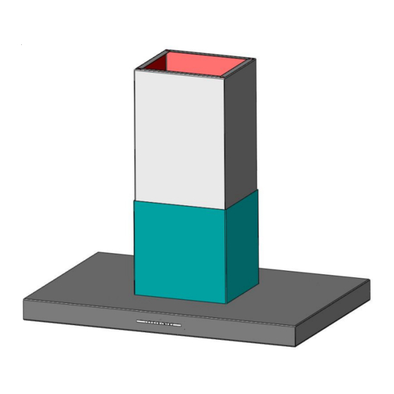
- Page 42 De elektrische aansluiting tot stand brengen 1 = boventoren (bedrijf met afgevoerde lucht). Wanneer een 2 = ondertoren externe blazermotor gebruikt wordt, de 3 = motormodule aansluitingskabel verbinden. 4 = lade voor sturing 5 = langsgaten voor kapbevestiging 6 = kaplichaam 12.
-
Page 43: Montage Eendelige Toren
-Montage eendelige toren 17.) Kunststof – De blinde stop op de module verwijderen (4 stuks) Uitvoering circulatieluchttoren bij eiland- kappen 18.) De plaatschroef op de module uitdraaien (4 stuks) 19.) Metalen clips in de buis schuiven en in de moer insluiten, eventueel met een hamer (4 stuks) Uitvoering circulatieluchttoren bij wand- kappen... -
Page 44: Afvoeren Van De Verpakking
21.) Metaalclips met buis van boven met het deksel van de motormodule vastschroeven ( 4 x ). 22.) Nu de tapstangen in de buis steken. De kap kan nu met de tapstangen gemonteerd Afvoeren van de verpakking worden. De verpakking van het apparaat kan worden gerecycled. - Page 45 X = screw for ceiling M8 = threaded rod for hood suspension...
- Page 46 Befestigung Wandhaube Abb. Model Campo / Palma Befestigung Inselhaube...
- Page 47 Typ: Sommer - Winterschaltung / VSA sep. Anleitung hierzu beachten!
- Page 48 Exklusiv-Hauben Mühlackerstraße 77 D-75417 Mühlacker Tel. (49) 0 70 41/8 82-0 Fax (49) 0 70 41/4 68 82 Internet: http://www.gutmann-exklusiv.de E-Mail: info@gutmann-exklusiv.de HRB 705602 Amtsgericht Mannheim DE263391836 Index 08 / 14 Artikel Nr.: 67201350...