Hitachi C 12FSA Mode D'emploi Et Instructions De Securite
Table des Matières
Les langues disponibles
Les langues disponibles
Liens rapides
All manuals and user guides at all-guides.com
MODEL
C 12FSA
MODÈLE
MODELO
INSTRUCTION MANUAL AND SAFETY INSTRUCTIONS
Improper and unsafe use of this power tool can result in death or serious bodily injury!
This manual contains important information about product safety. Please read and
understand this manual before operating the power tool. Please keep this manual
available for others before they use the power tool.
MODE D'EMPLOI ET INSTRUCTIONS DE SECURITE
Une utilisation incorrecte et dangereuse de cet outil motorisé peut entraîner la mort
ou de sérieuses blessures corporelles!
Ce mode d'emploi contient d'importantes informations à propos de la sécurité de
ce produit. Prière de lire et d'assimiler ce mode d'emploi avant d'utiliser l'outil
motorisé. Garder ce mode d'emploi à la disponibilité des autres utilisateurs avant
qu'ils utilisent l'outil motorisé.
MANUAL DE INSTRUCCIONES E INSTRUCCIONES DE SEGURIDAD
¡La utilización inapropiada e insegura de esta herramienta eléctrica puede resultar
en lesiones serias o en la muerte!
Este manual contiene información importante sobre la seguridad del producto. Lea y
comprenda este manual antes de utilizar la herramienta eléctrica. Guarde este manual
para que puedan leerlo otras personas antes de que utilicen la herramienta eléctrica.
DOUBLE INSULATION
DOUBLE ISOLATION
AISLAMIENTO DOBLE
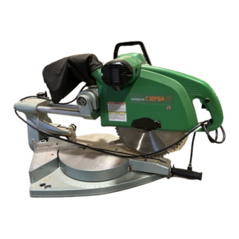
SLIDE COMPOUND SAW
SCIE A COUPE D'ONGLET RADIALE
TRONZADORA RADIAL ABATIBLE
WARNING
AVERTISSEMENT
ADVERTENCIA
Table des Matières

Manuels Connexes pour Hitachi C 12FSA


Sommaire des Matières pour Hitachi C 12FSA
- Page 1 All manuals and user guides at all-guides.com MODEL SLIDE COMPOUND SAW C 12FSA MODÈLE SCIE A COUPE D’ONGLET RADIALE MODELO TRONZADORA RADIAL ABATIBLE INSTRUCTION MANUAL AND SAFETY INSTRUCTIONS WARNING Improper and unsafe use of this power tool can result in death or serious bodily injury! This manual contains important information about product safety.
-
Page 2: Table Des Matières
All manuals and user guides at all-guides.com CONTENTS English Page Page IMPORTANT INFORMATION ........3 OPTIONAL ACCESSORIES ........10 MEANINGS OF SIGNAL WORDS ....... 3 APPLICATIONS ............10 PREPARATION BEFORE OPERATION ..... 11 SAFETY IMPORTANT SAFETY INSTRUCTIONS BEFORE USING ............12 BEFORE CUTTING ............13 FOR USING ALL POWER TOOLS ...... -
Page 27: Informations Importantes
AVERTISSEMENTS sur l’outil électrique et dans ce mode d’emploi. Ne jamais utiliser cet outil électrique d’une manière qui n’est pas spécifiquement recommandée par HITACHI sans avoir d’abord vérifié que l’utilisation prévue est sans danger pour vous et les autres. -
Page 28: Toujours Débrancher L'outil
Français All manuals and user guides at all-guides.com 8. PORTER DES VÊTEMENTS APPROPRIÉS PENDANT LE TRAVAIL. Ne jamais porter de vêtements lâches ni de gants, cravate, bagues, bracelets ni aucun autre bijou. Ils pourraient se coincer dans les pièces en rotation. Toujours porter des chaussures anti-dérapantes, en particulier avec des doigts de pied en acier. - Page 29 Français All manuals and user guides at all-guides.com Consignes de sécurité spéciales pour cet outil électrique AVERTISSEMENT: Pour éviter tout risque de blessure, les consignes de sécurité spéciales suivantes devront être respectées lors de l’utilisation de l’outil. CHOSES A FAIRE TOUJOURS OBSERVER LES CONSIGNES SUIVANTES POUR GARANTIR UNE UTILISA- TION EN TOUTE SÉCURITÉ: Bien lire le manuel et se familiariser avec les consignes de sécurité...
- Page 30 Français All manuals and user guides at all-guides.com CHOSES A NE PAS FAIRE POUR GARANTIR UNE UTILISATION EN TOUTE SÉCURITÉ, NE JAMAIS VIOLER LES CONSIGNES SUIVANTES: Ne jamais utiliser l’OUTIL ELECTRIQUE si l’on ne comprend pas bien les instructions de ce manuel. Ne jamais s’éloigner de l’OUTIL ELECTRIQUE sans débrancher auparavant son cordon d’alimentation.
-
Page 31: Pieces De Rechange
électrique. DOUBLE ISOLATION POUR UN FONCTIONNEMENT PLUS SUR Pour assurer un fonctionnement plus sûr de cet outil électrique, HITACHI a adopté une conception à double isolation. “Double isolation” signifie que deux systèmes d’isolation physiquement séparés ont été utilisés pour isoler les matériaux conducteurs d’ électrique connectés à l’outil électrique à partir du cadre extérieur manipulé... -
Page 32: Utilisation Et Entretien
Français All manuals and user guides at all-guides.com UTILISATION ET ENTRETIEN REMARQUE: Les informations contenues dans ce manuel sont destinées à vous aider à utiliser et à entretenir l’OUTIL ELECTRIQUE en toute sécurité. Certaines illustrations de ce manuel peuvent montrer des détails ou des fixations qui diffèrent de ceux de votre OUTIL ELECTRIQUE. -
Page 33: Spécifications
Français All manuals and user guides at all-guides.com SPÉCIFICATIONS Article Modèle C 12FSA Moteur Type Moteur à commutateur série Alimentation Courant alternatif monophasé 60 Hz Tension (volts) Courant à pleine charge (Amp) 12 Lame applicable Dia. extérieur 305 mm (12") Dia. -
Page 34: Accessoires Standard
Support de rallonge et butée (Fig. 1) (No. de code 320277) w Ensemble d’étau (A) (type horizontal, No. de code 305174) REMARQUE: Les accessoires sont sujets à changement sans obligation de la part de HITACHI. APPLICATIONS Cadres en bois et en aluminium. -
Page 35: Préparation Avant L'utilisation
Français All manuals and user guides at all-guides.com PRÉPARATION AVANT L’UTILISATION Avant de mettre l’outil électrique en service, effectuer les préparations suivantes : 1. Installation Boulon de 10 mm (13/32") Socle 2 orifices de 11 mm (7/16") 440mm (17-21/64") Etabli Ecrou de 10 mm (13/32") Fig. -
Page 36: Avant L'utilisation
Français All manuals and user guides at all-guides.com AVANT L’UTILISATION 1. S’assurer que la source d’alimentation convient pour l’outil. AVERTISSEMENT: Ne jamais raccorder l’outil électrique si l’alimentation secteur n’est pas de la tension spécifiée sur la plaque signalétique de l’outil Ne jamais raccorder l’outil à... -
Page 37: Avant La Coupe
Français All manuals and user guides at all-guides.com AVANT LA COUPE 1. Découpe d’une encoche dans la protection Le support (A) possède une protection (voir Fig. 8) dans laquelle il Garde (B) Support (A) Pièce faudra découper une encoche. Desserrer le bouton de boulonnage de 8 mm pour rentrer légèrement la protection. -
Page 38: Angle Oblique
Français All manuals and user guides at all-guides.com (2) Tourner le boulon de réglage de la profondeur de 8 mm pour régler la position de limite inférieure. (3) Quand le réglage est terminé, serrer à fond les deux écrous de 8 mm et l’écrou à oreilles de 8 mm. REMARQUE: Avant de serrer les deux écrous de 8 mm et l’écrou à... -
Page 39: Utilisation D'un Trait D'encre
Français All manuals and user guides at all-guides.com 7. Butée pour la précision de coupe ... (La butée est un accessoire en option.) Pièce Butée La butée facilite la précision des coupes continues sur des longueurs de 290 à 470 mm (11-13/32" à 18-1/2"). Support Pour installer la butée, la fixer au support à... -
Page 40: Fonctionnement De L'interrupteur
Français All manuals and user guides at all-guides.com 1. Fonctionnement de l’interrupteur Le bouton de déverrouillage de l’interrupteur à gâchette est conçu pour éviter tout fonctionnement inopiné pendant le travail. Pour Bouton de pouvoir utiliser l’outil électrique, il faudra tout d’abord enfoncer à déverrouillage Poignée fond le bouton de déverrouillage dans l’orifice de la poignée comme... -
Page 41: Coupe De Pièces Minces (Coupe À Pression Simple)
Français All manuals and user guides at all-guides.com 3. Coupe (1) Comme indiqué à la Fig. 19, la largeur de la lame est Ligne de réglage la largeur de coupe. En conséquence, glisser la pièce vers la droite (vue de la position de l’opérateur) pour obtenir la longueur b, et sur la gauche pour obtenir la longueur a. -
Page 42: Coupe De Pièces Volumineuses
Français All manuals and user guides at all-guides.com On abaissera donc la poignée doucement et avec soin. * Lors d’une coupe avec chariot, ramener délicatement la poignée (vers l’arrière) d’un mouvement régulier et ininterrompu. Le fait d’arrêter la poignée pendant la coupe laissera des marques de coupe peu esthétiques sur la pièce. -
Page 43: Procédure De Coupe D'onglet
Français All manuals and user guides at all-guides.com 8. Procédure de coupe d’onglet Echelle d’angle (1) Desserrer la poignée latérale et régler la plaque tournante jusqu’à ce que l’indicateur soit aligné sur le réglage voulu de l’échelle d’onglet (Fig. 26). (2) Resserrer la poignée latérale pour fixer la plaque tournante à... -
Page 44: Réglage D'une Coupe D'onglet
Français All manuals and user guides at all-guides.com Réglage d’une coupe d’onglet Si la plaque tournante est réglée sur l’un des angles décrits, déplacer la poignée latérale de réglage de la plaque tournante légèrement vers la droite ou vers la gauche pour stabiliser la position et aligner correctement l’échelle d’onglet et l’extrémité... - Page 45 Français All manuals and user guides at all-guides.com Garde Garde Table du socle Table du socle Fig. 30 Fig. 32 (3) Réglage de coupe en corniche complexe aux positions 1 et 4 de la Fig. 28 (voir Fig. 33 ; incliner la tête vers la droite) : q Tourner la plaque tournante vers la droite et régler l’angle d’onglet comme suit : * Pour des corniches complexes de type 45°...
-
Page 46: Procédures De Coupe D'encoche
Français All manuals and user guides at all-guides.com 11. Procédures de coupe d’encoche Boulon de réglage de la profondeur de 8 mm Ecrou à oreilles de 8 mm Découper les encoches avec la lame. Charnière Plaque tournante Trait inférieur de l’encoche Fig. -
Page 47: Utilisation Du Sac À Copeaux (Accessoire Standard)
Français All manuals and user guides at all-guides.com 13. Utilisation du sac à copeaux (Accessoire standard) (1) Si le sac à copeaux est plein, les copeaux sortent du sac quand Cache Conduit latéral (R) la lame tourne. Vérifier le sac à copeaux périodiquement et le vider avant qu’il ne soit plein. -
Page 48: Entretien Et Inspection
Français All manuals and user guides at all-guides.com ATTENTION :* Un guide-copeaux est installé à l’intérieur du cache latéral (L). Lors du retrait ou de l’installation de la lame, ne pas toucher le guide-copeaux. Cela pourrait casser ou ébrécher les extrémités de la lame. * Vérifier que le verrou d’axe est revenu en position rentrée après le retrait ou l’installation de la lame. -
Page 49: Inspection Des Vis De Montage
Français All manuals and user guides at all-guides.com 3. Inspecter les balais carbone (Fig. 43 et Fig. 44) Les balais carbone du moteur sont des pièces consommables. Si les balais en carbone sont usés, le moteur risque d’avoir des anomalies. En conséquence, inspecter périodiquement les balais en carbone et les remplacer lorsqu’ils ont atteint la limite d’usure comme indiqué... -
Page 50: Nettoyage
Pour garantir que seules des pièces de rechange agréées seront utilisées et que le système de double isolation sera protégé, il faudra confier toutes les opérations d’entretien (autres que l’entretien de routine) exclusivement à un SERVICE APRES-VENTE D’OUTILS ELECTRIQUES HITACHI AGREE. REMARQUE :... - Page 84 Issued by Shinagawa Intercity Tower A, 15-1, Konan 2-chome, Minato-ku, Tokyo 108-6020, Japan Distributed by Hitachi Koki U.S.A., Ltd. 3950 Steve Reynolds Blvd. Norcross, GA 30093 Hitachi Koki Canada Co. 6395 Kestrel Road Mississauga ON L5T 1Z5 Code No.