VEVOR C3A18 Pro Max Manuel D'utilisation
Table des Matières
Technical Support and E-Warranty Certificate
www.vevor.com/support
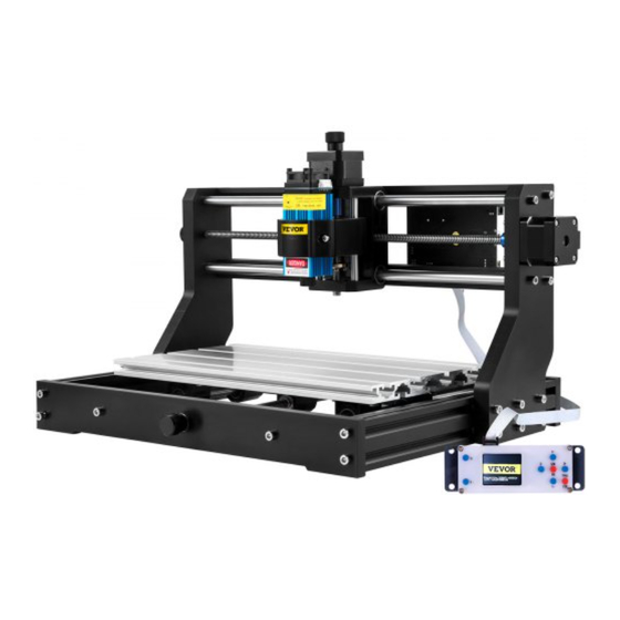
CNC ENGRAVING MACHINE
USER MANUAL
MODEL: C3A18 Pro Max
We continue to be committed to provide you tools with competitive price.
"Save Half", "Half Price" or any other similar expressions used by us only represents an
estimate of savings you might benefit from buying certain tools with us compared to the major
top brands and does not necessarily mean to cover all categories of tools offered by us. You
are kindly reminded to verify carefully when you are placing an order with us if you are
actually saving half in comparison with the top major brands.
Table des Matières

Manuels Connexes pour VEVOR C3A18 Pro Max


Sommaire des Matières pour VEVOR C3A18 Pro Max
- Page 1 CNC ENGRAVING MACHINE USER MANUAL MODEL: C3A18 Pro Max We continue to be committed to provide you tools with competitive price. "Save Half", "Half Price" or any other similar expressions used by us only represents an estimate of savings you might benefit from buying certain tools with us compared to the major top brands and does not necessarily mean to cover all categories of tools offered by us.
- Page 2 This is the original instruction, please read all manual instructions carefully before operating. VEVOR reserves a clear interpretation of our user manual. The appearance of the product shall be subject to the product you received. Please forgive us that we won't inform you again if...
-
Page 3: Important Safety Instructions
Warning-To reduce the risk of injury, user must read instructions manual carefully. Warning- Be sure to wear eye protectors when using this product. Indoor Use Only Avoiddirectlaserradiationoneyesorskin Do not touch any rotating parts when the machine is running Always wear protective glasses when use the machine Prohibited from use in flammable objects or gases Do not touch the socket with wet hand to reduce risk of electrocutions Please cut off the power immediately in case of emergency... - Page 4 MATTERS NEED ATTENTION Warning Please wear protective glasses when using the machine. In case your eyes hurt. Before replacing the tool, please disconnect the power supply of the machine to avoid accidents. Unplug the socket when not in use, before replacing parts and maintaining ...
-
Page 5: Parts List
1.Parts List C3A18 Pro Max Parts List Component A ( Alread assembled ) Part No Part Name E planation Quantit Picture Part No Part Name E planation Quantit Picture Aluminum profile 15180*300mm Guide block (X) Aluminum profile 2020*370mm,Black Aluminum profile... -
Page 6: Machine Assembly
2. Machine Assembly 13: Stepper motor 1PCS 15: Nut support seat 1PCS 15: Nut support seat 1PCS 11:Y Lead screw T8*308mm 1PCS 14: Muff coupling 1PCS 17: Spring 1PCS Press T8 nut to the bottom and turn Y Lead screw at the same time 12: T8 Nut 1PCS 25: Trapezoidal nut M5-20 12PCS... - Page 7 07: Connecting plate (right) 1PCS 25: Trapezoidal nut M5-20 6PCS Step ③ 21: M5*20 6PCS Screw Step ④ 19: Hand knob Z Φ5*18mm 1PCS 27: M4*5 1PCS Set Screw for knob Component A Component A Component A 08: X Smooth axis Φ10*370 2PCS 12: T8 Nut (X 1PCS 10: X Lead screw...
- Page 8 C1: Control board 1PCS 29: M5-10 4PCS Ship nut C2: Column 4PCS The plastic column must C3: M5*10 4PCS be assembled between Screw the control board and the aluminum parts. Step Step 30: Guard plate 2PCS 28: M5*8 8PCS Screw 29: M5-10 8PCS Ship nut...
- Page 9 3. Control-Board and Laser (Laser is optional) The terminal of the red dot of the spindle motor is positive, 3.1 Instructions for control board connection please plug in the red wire. The Motor-X/Y/Z interface on board should be connected to the X/Y/Z motors correspondingly.
-
Page 10: Home Button
4.1 States Work coordinates: Represents current X, Y & Z local coordinates of the CNC. Machine coordinates: Represents current X, Y & Z absolute machine coordinates. One of following CNC status: ◎ Idle - waiting for a G-code command Running - running a G-code command ◎... - Page 11 (3). Complete connection After setting the port and baud rate, click Finish. The status bar at the top right of the Candle interface will show Idle, and at the same time, the console at the bottom right will display the information shown below, indicating that the connection has been successfully established.
- Page 12 (6) Start carving After finding the engraving position, click the send button below and the device will automatically start engraving. The status bar at the top right shows running. The visualization window shows that the tool is moving along the tool path. You can choose the pause and stop buttons below when engraving.
- Page 13 (4). After the connection is successful, click “File” on the menu bar of the interface to enter the selection file interface, select “Open File”, import the picture to be engraved, etc. (5). Select the file to be engraved, click “Open”, the “Input Raster Image”dialog box will pop up. Here is the setting engraving mode and some other engraving parameters.
- Page 14 Q: What is the reason for the software connection failed? Please confirm whether the USB interface is in contact with normal. Please confirm whether the COM port is selected correctly (do not select COM1); please confirm whether the baud rate is selected correctly (select 115200). Q: How long does it take to engrave a picture? The length of time required for engraving depends mainly on the speed of the engraving, the speed of the idling, and the size of the picture.
- Page 15 Network status: There is a dot in the upper left corner of the main page. The dot indicates that VIGO-STK**** hotspot is active, and the GREEN dot indicates that the controller has connected to Local WiFi. The web management interface is as previous page. The web pages functions as follows: Click the menu "Control", the MOVE Control interface appears, you can click the corresponding button to control the CNC machine movement.
- Page 16 Please scan the QR code below to watch the machine assembly video. If the U disk in the machine kit can't be read, please scan the QR code to see how to download the software and related documents. Technical Support and E-Warranty Certificate www.vevor.com/support -15-...
- Page 17 Machine Translated by Google Assistance t echnique e t c ertificat d e g arantie électronique w ww.vevor.com/support MACHINE D E G RAVURE C NC MANUEL D 'UTILISATION MODÈLE : C 3A18 P ro M ax Nous c ontinuons à n ous e ngager à v ous f ournir d es o utils à d es p rix c ompétitifs.
-
Page 18: Assistance T Echnique E T C Ertificat D E G Arantie É Lectronique
Assistance t echnique e t c ertificat d e g arantie é lectronique www.vevor.com/support Il s 'agit d e l a n otice d 'utilisation d 'origine. V euillez l ire a ttentivement t outes l es ... -
Page 19: Consignes De Sécurité Importantes
Machine Translated by Google Avertissement P our r éduire l e r isque d e b lessure, l 'utilisateur d oit l ire l e m anuel d 'instructions soigneusement. Avertissement – A ssurezvous d e p orter d es l unettes d e p rotection l orsque v ous u tilisez c e p roduit. Utilisation ... - Page 20 Machine Translated by Google LES Q UESTIONS N ÉCESSITENT U NE A TTENTION P ARTICULIÈRE Avertissement u V euillez p orter d es l unettes d e p rotection l orsque v ous u tilisez l a m achine. E n c as d e c ontact a vec l es y eux, blesser.
- Page 21 Machine Translated by Google 1. L iste d es p ièces Liste d es p ièces d u C 3A18 P ro M ax Composant A ( déjà a ssemblé) Nom d e l a p ièce Nom d e l a p ièce Explication Numéro ...
-
Page 22: Assemblage De La Machine
Machine Translated by Google 2. A ssemblage d e l a m achine 13 : M oteur p as à p as 1 p ièce 15 : S iège d e s upport d 'écrou 1 PCS 15 : S iège d e s upport d 'écrou 1 PCS 11: ... - Page 23 Machine Translated by Google 1 p ièce Plaque d e c onnexion ( à d roite) 46 m m Écrou t rapézoïdal M520 6 p ièces Étape 21 : M5*20 6 p ièces Étape 19 : B outon à m ain ( Z) Φ 5*18mm 1 PCS 27 : ...
- Page 24 Machine Translated by Google C1 : C arte d e c ontrôle 1 PCS 29: M 510 4 p ièces Écrou d e b ateau C2 : C olonne 4 PCS La c olonne e n p lastique d oit C3 : M 5*10 4 p ièces être ...
- Page 25 Machine Translated by Google 3. C arte d e c ontrôle e t l aser ( le l aser e st f acultatif) Le t erminal d u p oint r ouge d e le m oteur d e l a b roche e st p ositif, v euillez 3.1 ...
- Page 26 Machine Translated by Google 4.1 É tats Coordonnées d e t ravail: Représente l es c oordonnées l ocales X , Y e t Z a ctuelles d e l a C NC. Coordonnées d e l a m achine : Représente ...
- Page 27 Machine Translated by Google (3). T erminer l a c onnexion A près avoir d éfini l e p ort e t l e d ébit e n b auds, c liquez s ur T erminer. L a b arre d 'état à le ...
- Page 28 Machine Translated by Google (6) C ommencer à s culpter Après a voir t rouvé l a p osition d e g ravure, c liquez s ur l e b outon d 'envoi c idessous e t l 'appareil c ommencera a utomatiquement l a g ravure. L a b arre d 'état à en ...
- Page 29 Machine Translated by Google (4). U ne f ois l a c onnexion é tablie, c liquez s ur « Fichier » d ans l a b arre d e m enu d e l 'interface p our a ccéder à l 'interface d e s élection d e f ichier, s électionnez « Ouvrir » Fichier”, ...
- Page 30 Machine Translated by Google Q : Q uelle e st l a r aison p our l aquelle l a c onnexion l ogicielle a é choué ? Veuillez c onfirmer s i l 'interface U SB e st e n c ontact n ormal. V euillez c onfirmer s i l e p ort C OM e st c orrectement s électionné ( ne p as sélectionnez ...
- Page 31 Machine Translated by Google État d u r éseau : u n p oint a pparaît d ans l e c oin s upérieur g auche d e l a p age p rincipale. L e p oint R OUGE i ndique q ue l e p oint d 'accès V IGOSTK**** e st a ctif e t l e p oint V ERT ...
-
Page 32: Guide D'entretien
Q R c ode p our v oir c omment t élécharger l e l ogiciel e t l es d ocuments a ssociés. Assistance t echnique e t c ertificat d e g arantie é lectronique w ww.vevor.com/support... - Page 33 CNC-GRAVURMASCHINE BENUTZERHANDBUCH MODELL: C3A18 Pro Max Wir sind weiterhin bestrebt, Ihnen Werkzeuge zu wettbewerbsfähigen Preisen anzubieten. „Sparen Sie die Hälfte“, „Halber Preis“ oder andere ähnliche Ausdrücke, die wir verwenden, stellen nur eine Schätzung der Ersparnis dar, die Sie beim Kauf bestimmter Werkzeuge bei uns im Vergleich zu den großen Topmarken erzielen können, und decken nicht unbedingt alle von uns angebotenen Werkzeugkategorien ab.
- Page 34 Dies ist die Originalanleitung. Bitte lesen Sie alle Anweisungen sorgfältig durch, bevor Sie das Gerät in Betrieb nehmen. VEVOR behält sich eine klare Auslegung unserer Bedienungsanleitung vor. Das Erscheinungsbild des Produkts richtet sich nach dem Produkt, das Sie erhalten haben.
-
Page 35: Wichtige Sicherheitshinweise
Machine Translated by Google Warnung: Um das Verletzungsrisiko zu verringern, muss der Benutzer die Bedienungsanleitung lesen sorgfältig. Warnung: Tragen Sie bei der Verwendung dieses Produkts unbedingt einen Augenschutz. Nur zur Verwendung im Innenbereich Vermeiden Sie direkte Laserstrahlung auf Augen oder Haut Berühren Sie keine rotierenden Teile, wenn die Maschine läuft Tragen Sie immer eine Schutzbrille, wenn Sie die Maschine benutzen Verboten für den Einsatz in brennbaren Objekten oder Gasen... - Page 36 Machine Translated by Google Angelegenheiten benötigen Aufmerksamkeit Warnung u Tragen Sie bei der Benutzung der Maschine eine Schutzbrille. Falls Ihre Augen verletzt. u Vor dem Austausch des Werkzeugs die Stromversorgung der Maschine trennen, um Unfälle vermeiden. u Ziehen Sie den Stecker aus der Steckdose, wenn Sie ihn nicht benutzen, bevor Sie Teile austauschen der Maschine.
- Page 37 Machine Translated by Google 1.Teileliste C3A18 Pro Max-Teileliste Komponente A (bereits montiert) Teile-Nr Teilename Teile-Nr Teilename Erläuterung Menge Bild Erklärung Menge Bild 15180 x 300 mm Aluminiumprofil —— Führungsblock (X) 2020 x 370 mm, Schwarz Aluminiumprofil 2040 x 295 mm, Schwarz Aluminiumprofil ——...
- Page 38 Machine Translated by Google 2. Maschinenmontage 13: Schrittmotor 1 STK 15: Mutternstützsitz 1 STK 15: Mutternstützsitz 1 STK 11:Y Leitspindel T8*308mm 1 STK 14: Muffenkupplung 1Stk 17: Feder 1 Stück T8 Mutter nach unten drücken und Drehen Sie gleichzeitig die Y-Leitspindel 12: T8 Mutter 1 STK Richtung Anschlusskabel...
- Page 39 Machine Translated by Google Anschlussplatte (rechts) 1 STÜCK 46 mm Trapezmutter M5-20 6 Stück Schritt ÿ 21: M5*20 6 STK Schrauben 19: Handknopf (Z) ÿ5 x 18 mm, 1 Stück Schritt ÿ 27: M4*5 1 STK Stellschraube für Knopf Komponente A Komponente A Komponente A 08: X Glatte Achse...
- Page 40 Machine Translated by Google C1: Steuerplatine 1 STK 29: M5-10 4 Stück Schiffsmutter C2: Spalte 4PCS Die Kunststoffsäule muss C3: M5 x 10, 4 Stück zwischen der Steuerplatine Schrauben und den Aluminiumteilen montiert werden. Schritt ÿ Schritt ÿ 30: Schutzplatte 2ST 28: M5 x 8, 8 Stück Schrauben 29: M5-10 8 Stück...
- Page 41 Machine Translated by Google 3. Steuerplatine und Laser (Laser ist optional) Das Terminal des roten Punktes von der Spindelmotor ist positiv, bitte stecken 3.1 Hinweise zum Anschluss der Steuerplatine Sie das rote Kabel ein. Die Motor-X/Y/Z-Schnittstelle an Bord sollte an die X/Y/Z-Motoren angeschlossen werden entsprechend.
- Page 42 Machine Translated by Google 4.1 Staaten Arbeitskoordinaten: Stellt die aktuellen lokalen X-, Y- und Z-Koordinaten der CNC dar. Maschinenkoordinaten: Stellt die aktuellen absoluten Maschinenkoordinaten X, Y und Z dar. Einer der folgenden CNC-Status: ÿ Leerlauf – Warten auf einen G-Code-Befehl. Läuft – Ausführen eines G-Code-Befehls. ÿ...
- Page 43 Machine Translated by Google (3). Verbindung herstellen Nach dem Einstellen von Port und Baudrate klicken Sie auf Fertig stellen. Die Statusleiste bei oben rechts auf der Candle-Oberfläche wird Idle angezeigt und gleichzeitig Zeit, die Konsole unten rechts zeigt die Informationen angezeigt und zeigt damit an, dass die Verbindung erfolgreich hergestellt wurde.
-
Page 44: Download Und Installation
Machine Translated by Google (6) Beginnen Sie mit dem Schnitzen Nachdem Sie die Gravurposition gefunden haben, klicken Sie unten auf die Schaltfläche Senden und das Gerät beginnt automatisch mit der Gravur. Die Statusleiste unter oben rechts wird „running“ angezeigt. Das Visualisierungsfenster zeigt, dass sich das Werkzeug entlang des Werkzeugpfads bewegt. Sie können die Pause wählen und Stopp-Tasten unten beim Gravieren. - Page 45 Machine Translated by Google (4). Nachdem die Verbindung erfolgreich hergestellt wurde, klicken Sie in der Menüleiste der Schnittstelle auf „Datei“, um die Dateiauswahlschnittstelle aufzurufen. Wählen Sie „Öffnen“ Datei“, zu gravierendes Bild importieren, usw. (5). Wählen Sie die zu gravierende Datei aus und klicken Sie auf „Öffnen“. Das Dialogfeld „Rasterbild eingeben“ wird angezeigt. Hier ist die Einstellung Gravur Modus und einige andere Gravurparameter.
- Page 46 Machine Translated by Google F: Was ist der Grund für den Fehler bei der Softwareverbindung? Bitte bestätigen Sie, ob die USB-Schnittstelle normal verbunden ist. Bitte bestätigen Sie, ob der COM-Port richtig ausgewählt ist (nicht wählen Sie COM1); bitte bestätigen Sie, ob die Baudrate richtig ausgewählt ist (wählen Sie 115200). F: Wie lange dauert die Gravur eines Bildes? Die Dauer der Gravur hängt hauptsächlich von der Geschwindigkeit der Gravur, der Leerlaufgeschwindigkeit und der Größe des Bild.
- Page 47 Machine Translated by Google Netzwerkstatus: In der oberen linken Ecke der Hauptseite befindet sich ein Punkt. Der ROTE Punkt zeigt an, dass der VIGO-STK****- Hotspot aktiv ist, und der GRÜNE Punkt zeigt an, dass der Controller mit dem lokalen WLAN verbunden ist. Die Web-Verwaltungsoberfläche ist wie auf der vorherigen Seite.
- Page 48 Bitte scannen Sie den QR-Code unten, um das Video zur Maschinenmontage anzusehen. Wenn die U-Disk im Maschinenkit nicht gelesen werden kann, scannen Sie bitte Klicken Sie auf den QR-Code, um zu erfahren, wie Sie die Software und die zugehörigen Dokumente herunterladen können. Technischer Support und E-Garantie-Zertifikat www.vevor.com/support -15-...
- Page 49 MACCHINA PER INCISIONE CNC MANUALE D'USO MODELLO: C3A18 Pro Max Continuiamo a impegnarci per fornirvi strumenti a prezzi competitivi. "Risparmia la metà", "Metà prezzo" o qualsiasi altra espressione simile da noi utilizzata rappresenta solo una stima del risparmio che potresti ottenere acquistando determinati utensili con noi rispetto ai principali marchi principali e non significa necessariamente coprire tutte le categorie di utensili da noi offerti.
- Page 50 Questa è l'istruzione originale, si prega di leggere attentamente tutte le istruzioni del manuale prima di utilizzare. VEVOR si riserva una chiara interpretazione del nostro manuale utente. L'aspetto del prodotto sarà soggetto al prodotto ricevuto. Vi preghiamo di perdonarci...
-
Page 51: Importanti Istruzioni Di Sicurezza
Machine Translated by Google Attenzione: per ridurre il rischio di lesioni, l'utente deve leggere il manuale di istruzioni accuratamente. Attenzione: indossare sempre protezioni per gli occhi quando si utilizza questo prodotto. Solo per uso interno Evitare la radiazione laser diretta sugli occhi o sulla pelle Non toccare le parti rotanti quando la macchina è... - Page 52 Machine Translated by Google LE QUESTIONI RICHIEDONO ATTENZIONE Avvertimento u Si prega di indossare occhiali protettivi quando si utilizza la macchina. Nel caso in cui i tuoi occhi male. u Prima di sostituire l'utensile, scollegare l'alimentazione elettrica della macchina per evitare incidenti.
-
Page 53: Elenco Delle Parti
Machine Translated by Google 1. Elenco delle parti Elenco dei componenti C3A18 Pro Max Componente A (già assemblato) Nome della parte Nome della parte Numero di parte Spiegazione Quantità Immagine Numero di parte Spiegazione Quantità Immagine 15180*300mm Profilo in alluminio ——... -
Page 54: Assemblaggio Della Macchina
Machine Translated by Google 2. Assemblaggio della macchina 13: Motore passo-passo 1 pz. 15: Supporto dado sedile 1 pz. 15: Supporto dado sedile 1 pz. 11:Y Vite di comando T8*308mm 1PZ 17: Primavera 1PZ 14: Giunto manicotto 1 pz. Premere il dado T8 verso il basso e girare contemporaneamente la vite di comando Y 12: Dado T8 1 PZ Direzione di... - Page 55 Machine Translated by Google 1 PZ Piastra di collegamento (destra) 46mm Dado trapezoidale M5-20 6 PZ Passo ÿ 21: M5*20 6 PZ Vite Passo ÿ 19: Manopola (Z)ÿ5*18mm 1 PZ 27: M4*5 1 pz Vite di fissaggio per manopola Componente A Componente A Componente A 08: X Asse liscio...
- Page 56 Machine Translated by Google C1: Scheda di controllo 1 PZ 29: M5-10 4 PZ Dato della nave C2: Colonna 4PCS La colonna in plastica deve C3: M5*10 4 PZ essere montata tra la Vite scheda di controllo e le parti in alluminio. Passo ÿ...
- Page 57 Machine Translated by Google 3. Scheda di controllo e laser (il laser è opzionale) Il terminale del punto rosso di il motore del mandrino è positivo, 3.1 Istruzioni per il collegamento della scheda di controllo collegare il filo rosso. L'interfaccia Motor-X/Y/Z a bordo dovrebbe essere collegato ai motori X/Y/Z corrispondentemente.
- Page 58 Machine Translated by Google 4.1 Stati Coordinate di lavoro: Rappresenta le coordinate locali X, Y e Z correnti del CNC. Coordinate della macchina: Rappresenta le coordinate assolute correnti della macchina X, Y e Z. Uno dei seguenti stati CNC: ÿ Inattivo - in attesa di un comando G-code In esecuzione - in esecuzione di un comando G-code ÿ...
- Page 59 Machine Translated by Google (3). Completamento della connessione Dopo aver impostato la porta e la velocità in baud, fare clic su Fine. La barra di stato in in alto a destra dell'interfaccia di Candle verrà visualizzato Idle e allo stesso tempo tempo, la console in basso a destra visualizzerà...
- Page 60 Machine Translated by Google (6) Inizia a scolpire Dopo aver trovato la posizione di incisione, clicca sul pulsante Invia qui sotto e il dispositivo inizierà automaticamente a incidere. La barra di stato a in alto a destra mostra running. La finestra di visualizzazione mostra che l'utensile si sta muovendo lungo il percorso utensile. Puoi scegliere la pausa e i pulsanti di arresto sottostanti durante l'incisione.
- Page 61 Machine Translated by Google (4). Dopo che la connessione è riuscita, fare clic su "File" sulla barra dei menu dell'interfaccia per accedere all'interfaccia di selezione del file, selezionare "Apri File”, importa l’immagine da incidere, ecc. (5). Selezionare il file da incidere, cliccare su “Apri”, apparirà la finestra di dialogo “Input Raster Image”. Ecco l’impostazione di incisione modalità...
-
Page 62: Pagina Principale
Machine Translated by Google D: Qual è la causa per cui la connessione software non è riuscita? Si prega di confermare che l'interfaccia USB sia in contatto con la norma. Si prega di confermare che la porta COM sia selezionata correttamente (non selezionare COM1);... - Page 63 Machine Translated by Google Stato della rete: c'è un punto nell'angolo in alto a sinistra della pagina principale. Il punto ROSSO indica che l'hotspot VIGO-STK**** è attivo, mentre il punto VERDE indica che il controller si è connesso al WiFi locale. L'interfaccia di gestione web è...
-
Page 64: Guida Alla Manutenzione
Si prega di scansionare il codice QR qui sotto per guardare il video di assemblaggio della macchina. Se il disco U nel kit della macchina non può essere letto, si prega di scansionare il codice QR per scoprire come scaricare il software e i documenti correlati. Supporto tecnico e certificato di garanzia elettronica www.vevor.com/support -15-... - Page 65 Machine Translated by Google Soporte t écnico y c ertificado d e g arantía electrónica w ww.vevor.com/support MÁQUINA D E G RABADO C NC MANUAL D EL U SUARIO MODELO: C 3A18 P ro M ax Seguimos c omprometidos a b rindarle h erramientas a p recios c ompetitivos.
- Page 66 Soporte t écnico y c ertificado d e g arantía e lectrónica www.vevor.com/support Estas s on l as i nstrucciones o riginales, l ea a tentamente t odas l as instrucciones d el m anual a ntes d e u tilizar e l p roducto. V EVOR s e r eserva u na ...
-
Page 67: Instrucciones De Seguridad Importantes
Machine Translated by Google Advertencia: P ara r educir e l r iesgo d e l esiones, e l u suario d ebe l eer e l m anual d e i nstrucciones. con c uidado. Advertencia: A segúrese d e u sar p rotectores p ara l os o jos c uando u tilice e ste p roducto. Uso ... - Page 68 Machine Translated by Google ASUNTOS Q UE N ECESITAN A TENCIÓN Advertencia u U tilice g afas p rotectoras c uando u tilice l a m áquina. E n c aso d e q ue s us o jos herir. u ...
- Page 69 Machine Translated by Google 1. L ista d e p iezas Lista d e p iezas d el C 3A18 P ro M ax Componente A ( Ya e nsamblado) Pieza N ro. Pieza N ro. Nombre d e l a p ieza Explicación Nombre ...
-
Page 70: Montaje De La Máquina
Machine Translated by Google 2. M ontaje d e l a m áquina 13: M otor p aso a p aso 1 p ieza 15: A siento d e s oporte d e t uerca 1 p ieza 15: ... - Page 71 Machine Translated by Google Placa d e c onexión ( derecha) 1 p iezas 46 m m Tuerca t rapezoidal M520 6 p iezas Paso 21: M 5*20 6 p iezas Tornillo Paso 19: P erilla d e m ano ( Z) Φ 5*18 m m 1 p ieza 27: ...
- Page 72 Machine Translated by Google C1: P laca d e c ontrol 1 p ieza 29: M 510 4 p iezas Tuerca d e b arco C2: C olumna 4 p iezas La c olumna d e p lástico d ebe C3: ...
- Page 73 Machine Translated by Google 3. T ablero d e c ontrol y l áser ( el l áser e s o pcional) La t erminal d el p unto r ojo d e El m otor d el h usillo e s p ositivo, c onecte 3.1 ...
- Page 74 Machine Translated by Google 4.1 E stados Coordenadas d e t rabajo: Representa l as c oordenadas l ocales X , Y y Z a ctuales d el C NC. Coordenadas d e l a m áquina: Representa ...
- Page 75 Machine Translated by Google (3) C onexión c ompleta D espués d e configurar e l p uerto y l a v elocidad e n b audios, h aga c lic e n F inalizar. L a b arra d e e stado e n La ...
- Page 76 Machine Translated by Google (6) C omience a t allar Después d e e ncontrar l a p osición d e g rabado, h aga c lic e n e l b otón d e e nvío a c ontinuación y e l d ispositivo c omenzará a g rabar a utomáticamente. L a b arra d e e stado e n La ...
- Page 77 Machine Translated by Google (4). U na v ez q ue l a c onexión s ea e xitosa, h aga c lic e n “ Archivo” e n l a b arra d e m enú d e l a i nterfaz p ara i ngresar a l a i nterfaz d e s elección d e a rchivo, s eleccione “ Abrir”. Archivo”, ...
- Page 78 Machine Translated by Google P: ¿ Cuál e s e l m otivo p or e l c ual f alló l a c onexión d el s oftware? Confirme s i l a i nterfaz U SB e stá e n c ontacto c on n ormalidad. C onfirme s i e l p uerto C OM e stá s eleccionado c orrectamente ( no seleccione ...
- Page 79 Machine Translated by Google Estado d e l a r ed: H ay u n p unto e n l a e squina s uperior i zquierda d e l a p ágina p rincipal. E l p unto R OJO i ndica ...
-
Page 80: G Uía D E M Antenimiento
ódigo Q R p ara v er c ómo d escargar e l s oftware y l os d ocumentos r elacionados. Soporte t écnico y c ertificado d e g arantía e lectrónica w ww.vevor.com/support... - Page 81 MASZYNA DO GRAWEROWANIA CNC INSTRUKCJA OBSŁUGI MODEL: C3A18 Pro Max Nadal staramy się oferować Państwu narzędzia w konkurencyjnych cenach. „Oszczędź połowę”, „Połowa ceny” lub inne podobne wyrażenia używane przez nas stanowią jedynie szacunkowe oszczędności, jakie możesz uzyskać, kupując u nas określone narzędzia w porównaniu z głównymi markami i niekoniecznie oznaczają...
- Page 82 To jest oryginalna instrukcja, przed użyciem należy uważnie przeczytać wszystkie instrukcje. VEVOR zastrzega sobie jasną interpretację naszej instrukcji obsługi. Wygląd produktu będzie zależał od produktu, który otrzymałeś. Prosimy o wybaczenie, że nie poinformujemy Cię ponownie, jeśli w naszym produkcie pojawią się jakiekolwiek aktualizacje technologiczne lub...
-
Page 83: Ważne Instrukcje Bezpieczeństwa
Machine Translated by Google Ostrzeżenie – aby zmniejszyć ryzyko obrażeń, użytkownik musi przeczytać instrukcję obsługi ostrożnie. Ostrzeżenie: Podczas stosowania tego produktu należy nosić okulary ochronne. Tylko do użytku wewnątrz pomieszczeń Unikaj bezpośredniego promieniowania laserowego na oczy lub skórę Nie dotykaj żadnych obracających się części, gdy maszyna pracuje. Podczas korzystania z maszyny należy zawsze nosić... - Page 84 Machine Translated by Google SPRAWY WYMAGAJĄCE UWAGI Ostrzeżenie u Podczas korzystania z urządzenia należy nosić okulary ochronne. W przypadku uszkodzenia oczu zraniony. Przed wymianą narzędzia należy odłączyć zasilanie maszyny, aby unikaj wypadków. u Odłączaj gniazdo, gdy nie jest używane, przed wymianą części lub konserwacją. maszyna.
-
Page 85: Lista Części
Machine Translated by Google 1. Lista części Lista części C3A18 Pro Max Komponent A (już zmontowany) Nazwa części Nazwa części Numer części Wyjaśnienie Ilość Obrazek Numer części Wyjaśnienie Ilość Obraz 15180*300mm Profil aluminiowy —— Blok prowadzący (X) 2020*370mm,Czarny Profil aluminiowy... - Page 86 Machine Translated by Google 2. Montaż maszyn 13: Silnik krokowy 1 szt. 15: Podkładka pod nakrętkę 1 szt. 15: Podkładka pod nakrętkę 1 szt. 11:Y Śruba pociągowa T8*308mm 1 szt 14: Złącze mufowe 1 szt. 17: Wiosna 1 szt. Wciśnij nakrętkę T8 do dołu i jednocześnie obrócić...
- Page 87 Machine Translated by Google 1 SZT. Płyta łącząca (prawa) 46mm Nakrętka trapezowa M5-20 6 SZT. Krok 21: M5*20 6 SZT. Śruba Krok 19: Gałka ręczna (Z)Φ5*18mm 1 szt. 27: M4*5 1 szt. Śruba ustalająca do pokrętła Składnik A Składnik A Składnik A 08: X Gładka oś...
- Page 88 Machine Translated by Google C1: Płyta sterownicza 1 szt. 29: M5-10 4 SZT. Orzech okrętowy C2: Kolumna 4PCS Kolumnę plastikową należy C3: M5*10 4 SZT. zamontować pomiędzy płytą Śruba sterowniczą a częściami aluminiowymi. Krok Krok 30: Płyta ochronna 2szt 28: M5*8 8 SZT. Śruba 29: M5-10 8 SZT.
- Page 89 Machine Translated by Google Terminal czerwonej kropki 3. Płyta sterownicza i laser (laser jest opcjonalny) silnik wrzeciona jest dodatni, proszę 3.1 Instrukcja podłączenia płyty sterującej podłączyć czerwony przewód. Interfejs Motor-X/Y/Z na pokładzie powinien być podłączonym do silników X/Y/Z odpowiednio. Wtyczka 6Pin jest przeznaczona do silnik, a 4-pinowy jest do panelu sterowania.
- Page 90 Machine Translated by Google 4.1 Stany Współrzędne pracy: Reprezentuje aktualne lokalne współrzędne X, Y i Z CNC. Współrzędne maszyny: Reprezentuje aktualne współrzędne absolutne maszyny X, Y i Z. Jeden z następujących statusów CNC: Bezczynny — oczekiwanie na polecenie G-code Uruchomiony — uruchamianie polecenia G-code Strona główna - cykl powrotu do domu jest wykonywany Sprawdź...
- Page 91 Machine Translated by Google (3). Zakończ połączenie Po ustawieniu portu i szybkości transmisji kliknij Zakończ. Pasek stanu na w prawym górnym rogu interfejsu Candle będzie widoczny stan bezczynności, a jednocześnie w prawym dolnym rogu konsoli będą wyświetlane informacje pokazano poniżej, wskazując, że połączenie zostało pomyślnie nawiązane przyjęty.
- Page 92 Machine Translated by Google (6) Rozpocznij rzeźbienie Po znalezieniu pozycji grawerowania kliknij przycisk wysyłania poniżej, a urządzenie automatycznie rozpocznie grawerowanie. Pasek stanu na prawy górny róg pokazuje bieganie. Okno wizualizacji pokazuje, że narzędzie porusza się wzdłuż ścieżki narzędzia. Możesz wybrać pauzę i przyciski stop poniżej podczas grawerowania.
- Page 93 Machine Translated by Google (4) Po pomyślnym nawiązaniu połączenia kliknij „Plik” na pasku menu interfejsu, aby wejść do interfejsu wyboru pliku, wybierz „Otwórz Plik”, zaimportuj obraz, który chcesz wygrawerować, itd. (5). Wybierz plik do grawerowania, kliknij „Otwórz”, pojawi się okno dialogowe „Wprowadź obraz rastrowy”. Oto ustawienia grawerowania tryb i niektóre inne parametry grawerowania.
-
Page 94: Strona Główna
Machine Translated by Google P: Jaka jest przyczyna braku połączenia z oprogramowaniem? Proszę potwierdzić, czy interfejs USB jest w kontakcie z normalnym. Proszę potwierdzić, czy port COM jest wybrany prawidłowo (nie wybierz COM1); sprawdź czy wybrana prędkość transmisji jest prawidłowa (wybierz 115200). P: Jak długo trwa wygrawerowanie obrazu? Czas potrzebny do grawerowania zależy głównie od szybkości grawerowania, prędkości biegu jałowego i rozmiaru obraz. - Page 95 Machine Translated by Google Status sieci: W lewym górnym rogu strony głównej znajduje się kropka. CZERWONA kropka oznacza, że hotspot VIGO-STK**** jest aktywny, a ZIELONA kropka oznacza, że kontroler połączył się z lokalnym WiFi. Interfejs zarządzania siecią jest taki sam jak na poprzedniej stronie. Strony internetowe działają następująco: Kliknij menu „Sterowanie”, pojawi się...
- Page 96 Zeskanuj poniższy kod QR, aby obejrzeć film o montażu maszyny. Jeśli nie można odczytać dysku U w zestawie maszyny, zeskanuj go kod QR, aby dowiedzieć się, jak pobrać oprogramowanie i powiązane dokumenty. Wsparcie techniczne i certyfikat gwarancji elektronicznej www.vevor.com/support -15-...
- Page 97 CNC GRAVEERMACHINE GEBRUIKERSHANDLEIDING MODEL: C3A18 Pro Max Wij streven er voortdurend naar om u gereedschappen tegen concurrerende prijzen te leveren. "Save Half", "Half Price" of andere soortgelijke uitdrukkingen die wij gebruiken, geven alleen een schatting van de besparingen die u kunt behalen door bepaalde gereedschappen bij ons te kopen in vergelijking met de grote topmerken en betekent niet noodzakelijkerwijs dat alle categorieën gereedschappen die wij aanbieden, worden gedekt.
- Page 98 Dit is de originele instructie, lees alle handleidingen zorgvuldig door voordat u het product gebruikt. VEVOR behoudt zich een duidelijke interpretatie van onze gebruikershandleiding voor. Het uiterlijk van het product is afhankelijk van het product dat u hebt ontvangen. Vergeef ons dat we u niet...
-
Page 99: Belangrijke Veiligheidsinstructies
Machine Translated by Google Waarschuwing - Om het risico op letsel te verminderen, moet de gebruiker de gebruiksaanwijzing lezen voorzichtig. Waarschuwing: draag altijd een oogbescherming wanneer u dit product gebruikt. Alleen voor gebruik binnenshuis Vermijd directe laserstraling op de ogen of de huid Raak geen draaiende onderdelen aan als de machine draait Draag altijd een veiligheidsbril wanneer u de machine gebruikt Verboden te gebruiken in ontvlambare voorwerpen of gassen... - Page 100 Machine Translated by Google ZAKEN HEBBEN AANDACHT NODIG Waarschuwing u Draag een beschermende bril als u de machine gebruikt. Mocht uw ogen pijn doen. u Voordat u het gereedschap vervangt, dient u de stroomtoevoer naar de machine los te koppelen om ongelukken voorkomen.
- Page 101 Machine Translated by Google 1.Onderdelenlijst C3A18 Pro Max Onderdelenlijst Component A (al gemonteerd) Onderdeelnr. Onderdeelnaam Onderdeelnr. Onderdeelnaam Uitleg Hoeveelheid Afbeelding Uitleg Hoeveelheid Afbeelding 15180*300mm Aluminium profiel —— Geleidingsblok (X) 2020*370mm, Zwart Aluminium profiel 2040*295mm, Zwart Aluminium profiel —— Geleidingsblok (Z)
-
Page 102: Machine-Assemblage
Machine Translated by Google 2. Machine-assemblage 13: Stappenmotor 1PCS 15: Moersteunzitting 1PCS 15: Moersteunzitting 1PCS 11:Y Leidingsschroef T8*308mm 1PCS 14: Muff-koppeling 1PCS 17: Lente 1PCS Druk de T8-moer naar beneden en draai tegelijkertijd de Y-spindel 12: T8 moer 1PCS Richting van 13: Stappenmotor 1PCS verbindingsdraad 25: Trapeziummoer... - Page 103 Machine Translated by Google Verbindingsplaat (rechts) 1 STUKS 46mm Trapeziummoer M5-20 6STUKS Stap ÿ 21: M5*20 6 STUKS Schroef Stap ÿ 19: Handknop (Z) ÿ5 * 18mm 1PCS 27: M4*5 1PCS Stelschroef voor knop Onderdeel A Onderdeel A Onderdeel A 08: X Gladde as ÿ10*370 2PCS 12: T8 moer (X)1PCS...
- Page 104 Machine Translated by Google C1: Besturingskaart 1PCS 29: M5-10 4PCS Scheepsmoer C2: Kolom 4PCS De kunststof kolom moet tussen C3: M5*10 4 STUKS het bedieningspaneel en de Schroef aluminium onderdelen worden gemonteerd. Stap ÿ Stap ÿ 30: Beschermplaat 2PCS 28: M5*8 8STUKS Schroef 29: M5-10 8STUKS Scheepsmoer...
- Page 105 Machine Translated by Google 3. Controlebord en laser (laser is optioneel) Het uiteinde van de rode stip van De spindelmotor is positief, sluit de rode 3.1 Instructies voor het aansluiten van het bedieningspaneel draad aan. De Motor-X/Y/Z-interface aan boord moet worden aangesloten op de X/Y/Z-motoren overeenkomstig.
- Page 106 Machine Translated by Google 4.1 Staten Werkcoördinaten: Geeft de huidige lokale X-, Y- en Z-coördinaten van de CNC weer. Machinecoördinaten: Geeft de huidige absolute X-, Y- en Z-machinecoördinaten weer. Een van de volgende CNC-statussen: ÿ Inactief - wachtend op een G-code-opdracht. Actief - een G-code-opdracht uitvoeren. ÿ...
- Page 107 Machine Translated by Google (3). Voltooi de verbinding Nadat u de poort en de baudrate hebt ingesteld, klikt u op Voltooien. De statusbalk bij rechtsboven in de Candle-interface wordt Idle weergegeven, en tegelijkertijd tijd, de console rechtsonder zal de informatie weergeven hieronder weergegeven, wat aangeeft dat de verbinding succesvol is gemaakt gevestigd.
- Page 108 Machine Translated by Google (6) Begin met snijden Nadat u de graveerpositie hebt gevonden, klikt u op de knop Verzenden hieronder en het apparaat begint automatisch met graveren. De statusbalk bij rechtsboven toont running. Het visualisatievenster toont dat het gereedschap langs het gereedschapspad beweegt. U kunt de pauze kiezen en stopknoppen hieronder tijdens het graveren.
- Page 109 Machine Translated by Google (4) Nadat de verbinding succesvol is, klikt u op "Bestand" in de menubalk van de interface om de interface voor het selecteren van bestanden te openen, selecteert u "Openen" Bestand”, importeer de te graveren afbeelding, enz. (5).
- Page 110 Machine Translated by Google V: Wat is de reden dat de softwareverbinding mislukt? Controleer of de USB-interface in contact is met normaal. Controleer of de COM-poort correct is geselecteerd (niet selecteer COM1); controleer of de baudrate correct is geselecteerd (selecteer 115200). V: Hoe lang duurt het om een foto te graveren? De tijd die nodig is voor het graveren hangt voornamelijk af van de graveersnelheid, de stationairloopsnelheid en de grootte van de afbeelding.
- Page 111 Machine Translated by Google Netwerkstatus: Er is een stip in de linkerbovenhoek van de hoofdpagina. De RODE stip geeft aan dat de VIGO-STK**** hotspot actief is, en de GROENE stip geeft aan dat de controller verbinding heeft gemaakt met Local WiFi. De webbeheerinterface is zoals op de vorige pagina.
- Page 112 Scan de QR-code hieronder om de video over de machinemontage te bekijken. Als de U-schijf in de machinekit niet kan worden gelezen, scan dan de QR-code om te zien hoe u de software en bijbehorende documenten kunt downloaden. Technische ondersteuning en e-garantiecertificaat www.vevor.com/support -15-...
- Page 113 CNC-GRAVERMASKIN ANVÄNDARMANUAL MODELL: C3A18 Pro Max Vi fortsätter att vara engagerade i att ge dig verktyg till konkurrenskraftiga priser. "Spara hälften", "halva priset" eller andra liknande uttryck som används av oss representerar bara en uppskattning av besparingar du kan dra nytta av att köpa vissa verktyg hos oss jämfört med de stora toppmärkena och betyder inte nödvändigtvis att täcka alla kategorier av verktyg som erbjuds...
- Page 114 Detta är den ursprungliga instruktionen, läs alla instruktioner noggrant innan du använder den. VEVOR reserverar sig för en tydlig tolkning av vår användarmanual. Utseendet på produkten är beroende av den produkt du fått. Ursäkta oss att vi inte kommer att informera dig igen om...
-
Page 115: Viktiga Säkerhetsinstruktioner
Machine Translated by Google Varning - För att minska risken för skada måste användaren läsa bruksanvisningen försiktigt. Varning- Var noga med att bära ögonskydd när du använder denna produkt. Endast för inomhusbruk Undvik direkt laserstrålning av ögonskinn Rör inte vid några roterande delar när maskinen är igång Bär alltid skyddsglasögon när du använder maskinen Förbjudet att använda i brandfarliga föremål eller gaser Rör inte vid uttaget med våta händer för att minska risken för elektriska stötar... - Page 116 Machine Translated by Google ÄRenden BEHÖVER UPPMÄRKSAMHET Varning u Bär skyddsglasögon när du använder maskinen. I fall dina ögon skada. u Innan du byter ut verktyget, vänligen koppla bort maskinens strömförsörjning till undvika olyckor. u Koppla ur uttaget när det inte används, innan du byter ut delar och underhåller maskinen.
- Page 117 Machine Translated by Google 1.Delarlista C3A18 Pro Max reservdelslista Komponent A (Redan monterad) Delnr Delens namn Delnr Delens namn Förklaring Kvantitet Bild Förklaring Kvantitet Bild 15180*300mm Aluminiumprofil —— Styrblock (X) 2020*370 mm, svart Aluminiumprofil 2040*295 mm, svart Aluminiumprofil —— Styrblock (Z)
- Page 118 Machine Translated by Google 2. Maskinmontering 13: Stegmotor 1st 15: Mutterstödssäte 1st 15: Mutterstödssäte 1st 11:Y Blyskruv T8*308mm 1ST 17: Vår 1st 14: Muffkoppling 1ST Tryck ner T8-muttern till botten och vrid samtidigt Y-skruven 12: T8 Mutter 1st Riktning av 13: Stegmotor 1st anslutningstråd 25: Trapetsmutter...
- Page 119 Machine Translated by Google 1 st Anslutningsplatta (höger) 46 mm Trapetsformad mutter M5-20 6st Steg ÿ 21: M5*20 6 st Skruva 19: Handknopp(Z)ÿ5*18mm 1st Steg ÿ 27: M4*5 1ST Ställskruv för knopp Komponent A Komponent A Komponent A 08: X Slät axel ÿ10*370 2PCS 12: T8 Mutter (X)1 STK 10: X Blyskruv...
- Page 120 Machine Translated by Google C1: Styrkort 1st 29: M5-10 4ST Skeppsmutter C2: Kolumn 4PCS Plastpelaren ska monteras C3: M5*10 4ST mellan styrkortet och Skruva aluminiumdelarna. Steg ÿ Steg ÿ 30: Skyddsplåt 2ST 28: M5*8 8PCS Skruva 29: M5-10 8st Skeppsmutter...
- Page 121 Machine Translated by Google 3. Styrkort och laser (laser är valfritt) Terminalen av den röda pricken av spindelmotorn är positiv, anslut den 3.1 Instruktioner för anslutning av styrkort röda kabeln. Motor-X/Y/Z-gränssnittet ombord ska kopplas till X/Y/Z-motorerna motsvarande. 6-stiftskontakten är för motor, och 4Pin är för kontrollpanelen.
- Page 122 Machine Translated by Google 4.1 Stater Arbetskoordinater: Representerar nuvarande X, Y & Z lokala koordinater för CNC. Maskinkoordinater: Representerar aktuella X, Y & Z absoluta maskinkoordinater. En av följande CNC-status: ÿ Inaktiv - väntar på ett G-kodkommando Körs - kör ett G-kodkommando ÿ...
- Page 123 Machine Translated by Google (3). Komplett anslutning När du har ställt in porten och baudhastigheten klickar du på Slutför. Statusfältet kl den övre högra delen av Candle-gränssnittet kommer att visa Idle, och samtidigt tid kommer konsolen längst ner till höger att visa informationen visas nedan, vilket indikerar att anslutningen har lyckats etablerad.
- Page 124 Machine Translated by Google (6) Börja tälja När du har hittat graveringspositionen klickar du på skicka-knappen nedan så börjar enheten automatiskt gravera. Statusfältet kl uppe till höger visar löpning. Visualiseringsfönstret visar att verktyget rör sig längs verktygsbanan. Du kan välja paus och stoppknappar nedan vid gravering.
- Page 125 Machine Translated by Google (4). När anslutningen har lyckats, klicka på "Arkiv" på menyraden i gränssnittet för att gå in i gränssnittet för val av fil, välj "Öppna Arkiv”, importera bilden som ska graveras osv. (5). Välj filen som ska graveras, klicka på "Öppna", dialogrutan "Mata in rasterbild" kommer att dyka upp. Här är inställningsgravyren läge och några andra graveringsparametrar.
- Page 126 Machine Translated by Google F: Vad är orsaken till att mjukvaruanslutningen misslyckades? Bekräfta om USB-gränssnittet är i kontakt med normalt. Kontrollera om COM-porten är korrekt vald (gör inte välj COM1); vänligen bekräfta om baudhastigheten är korrekt vald (välj 115200). F: Hur lång tid tar det att gravera en bild? Hur lång tid som krävs för gravering beror främst på...
- Page 127 Machine Translated by Google Nätverksstatus: Det finns en prick i det övre vänstra hörnet på huvudsidan. Den RÖDA punkten indikerar att VIGO-STK**** hotspot är aktiv, och den GRÖNA punkten indikerar att kontrollern har anslutit till lokalt WiFi. Webbhanteringsgränssnittet är som föregående sida. Webbsidorna fungerar enligt följande: Klicka på...
- Page 128 9. Monteringsvideo och onlineguide Skanna QR-koden nedan för att se videon om maskinmontering. Om U-skivan i maskinsatsen inte kan läsas, vänligen skanna QR-koden för att se hur du laddar ner programvaran och relaterade dokument. Teknisk support och e-garanticertifikat www.vevor.com/support -15-...