Table des Matières
Publicité
Les langues disponibles
Les langues disponibles
Liens rapides
READ AND SAVE THESE INSTRUCTIONS
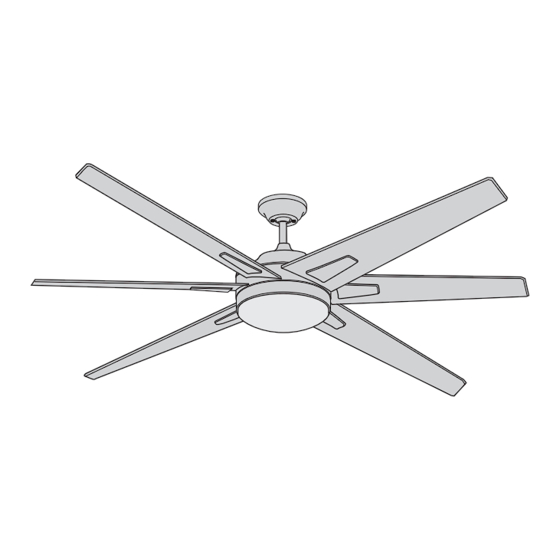
Ceiling Fan Owner's Manual
CF915TM60BS00 -
CF915TM60GRT00 -
CF915W60BS00 -
CF915W60ORB00 -
CF915TM72BS00 -
CF915TM72GRT00 -
CF915W72BS00 -
CF915W72ORB00 -
Questions, problems, missing parts: Before returning to the store call
Emerson Electric Customer Service - 8 a.m. - 6 p.m., Eastern, Monday-Friday
Part No. F40BP75280002
Revision: 180515
RAH ECO
Model Numbers
Brushed Steel with 60" Timber Gray Blades
Graphite with 60" Timber Gray Blades
Brushed Steel with 60" Sunburst Walnut Blades
Oil Rubbed Bronze with 60" Sunburst Walnut Blades
Brushed Steel with 72" Timber Gray Blades
Graphite with 72" Timber Gray Blades
Brushed Steel with 72" Sunburst Walnut Blades
Oil Rubbed Bronze with 72" Sunburst Walnut Blades
17.6
Net Weight:
1-800-654-3545
www.emersonfans.com
Lbs.
• Español - página 31
• Français - page 61
Form No. BP7528-2
U.L. Model No.: CF915
Publicité
Table des Matières

Manuels Connexes pour Emerson RAH ECO CF915TM60BS00


Sommaire des Matières pour Emerson RAH ECO CF915TM60BS00
- Page 1 17.6 Net Weight: Lbs. Questions, problems, missing parts: Before returning to the store call Emerson Electric Customer Service - 8 a.m. - 6 p.m., Eastern, Monday-Friday • Español - página 31 • Français - page 61 1-800-654-3545 Part No. F40BP75280002 Form No.
-
Page 2: Table Des Matières
Model No. RH-786NRW, manufactured by Rhine Electric Co., Ltd. To avoid fire, shock or injury, do not use an Emerson or 1. To avoid possible shock, be sure electricity is turned off... -
Page 3: Unpacking Instructions
Emerson Electric Shade Co. Substitution of parts or accessories not designated LED Light Fixture Assembly for use with this product by Emerson Electric Co. could Medallions result in personal injury or property damage. Fan Support Plates... -
Page 4: Tools Needed For Assembly
One 1/4” Blade Screwdriver One Wire Stripper regulate your ceiling fan speed and light control. Materials This Emerson Ceiling Fan may be used with the following accessory (purchased separately): SR600 Remote Wiring outlet box and box connectors must be of type Control. -
Page 5: Ceiling Fan Assembly
3. Ceiling Fan Assembly Remove and discard the Cardboard Shipping Retainers from the Fan Motor Assembly (Figure 1). FAN MOTOR ASSEMBLY CARDBOARD SHIPPING RETAINERS (2) Figure 1 NOTE: Be sure NOT to loosen or remove the Green GREEN GROUND WIRE Ground Wire Screw. -
Page 6: Clevis Pin
3. Ceiling Fan Assembly (Continued) Loosen the two Phillips Head Set Screws in the Motor DOWNROD Coupler for installation of the Downrod (Figure 4). Seat the Downrod in the Motor Coupler (Figure 4). MOTOR COUPLER LOOSEN PHILLIPS HEAD SET SCREWS (2) Figure 4 Align the Clevis Pin holes in the Downrod with the holes in the Motor Coupler. - Page 7 3. Ceiling Fan Assembly (Continued) Make sure the Grommet is properly installed in the Coupler GROMMET Cover then slide the Coupler Cover on the Downrod until it rests on the Fan Motor Assembly (Figure 7). COUPLER COVER DOWNROD FAN ASSEMBLY Figure 7 Place the Ceiling Cover over the Downrod.
- Page 8 3. Ceiling Fan Assembly (Continued) NOTE: Only use the Hanger Ball supplied with this MOTOR LEADS Ceiling Fan. DOWNROD Reinstall the Hanger Ball (Figure 9) on the Downrod as follows: CEILING COVER Route the two 80-inch Motor Leads through the Hanger HANGER Ball and slide the Hanger Ball over the Downrod.
-
Page 9: How To Hang Your Ceiling Fan
4. How to Hang Your Ceiling Fan WARNING CEILING The fan must be hung with at least 7' of clearance from floor to blades (Figure 11). WARNING Turning off wall switch is not sufficient. To avoid possible electrical shock, be sure electricity is turned off at the main fuse box before wiring. - Page 10 4. How to Hang Your Ceiling Fan (Continued) Remove the Socket Head Cap Screw with the Hex Wrench (supplied in the parts bag) from the Retaining Strap to the Hanger Bracket (Figure 13); retain the Socket OUTLET Head Cap Screw for future use. Swing open the Retaining Strap as shown in Figure 13.
-
Page 11: How To Wire Your Ceiling Fan
Co. Substitution of parts or accessories not designated to the Grounding Conductor of Supply (this may be a bare for use with this product by Emerson Electric Co. could wire or wire with green colored insulation). result in personal injury or property damage. - Page 12 5. How to Wire Your Ceiling Fan (Continued) Securely connect the Fan Motor White Wire to the Supply White (neutral) Wire using a Wire Connector (supplied) (Figure 17). SUPPLY WHITE (NEUTRAL) LISTED WIRE CONNECTOR FAN MOTOR WHITE WIRE Figure 17 Securely connect the Fan Motor Black Wire to the Supply Black (hot) Wire using a Wire Connector (supplied) (Figure 18).
-
Page 13: Final Installation
5. How to Wire Your Ceiling Fan (Continued) Screw the two Threaded Studs (supplied) into the tapped holes in the Hanger Bracket (Figure 20). Your Fan is now wired to be turned on and off from the Fan Switch. HANGER BRACKET THREADED STUD (2) -
Page 14: 18Mm Phillips Washer Head Screws
6. Final Installation (Continued) Mount a Medallion to the Fan Blade using three 10-24 x 3/8" PHILLIPS WASHER HEAD 10-24 x 3/8” Phillips Washer Head Screws and three Fiber SCREWS (3 per blade) Washers (supplied) (Figure 22). Complete the remaining five Blades Assemblies per the above instructions. -
Page 15: 10 #8-32 X 3/8" Pan Head Screw (Spare)
6. Final Installation (Continued) Remove and retain one of the three #8-32 x 3/8” Pan Head Screws in the Fan Motor Assembly. Loosen the remaining two #8-32 x 3/8” Pan Head Screws (Figure 24). FAN MOTOR ASSEMBLY LOOSEN TWO #8-32 x 3/8" PAN HEAD SCREWS REMOVE ONE #8-32 x 3/8"... - Page 16 6. Final Installation (Continued) Remove and retain one of the three #8-32 x 3/8” Pan Head Screws from the Lower Housing. Loosen the remaining two #8-32 x 3/8” Pan Head Screws (Figure 26). LOWER HOUSING REMOVE ONE #8-32 x 3/8" PAN HEAD SCREW LOOSEN TWO #8-32 x 3/8"...
- Page 17 Dimples on the inside of the Lower Housing (Figure 29). Then turn the Shade clockwise until it stops turning. NOTE: Periodically check that the Shade is seated fully clockwise in the Lower Housing. Please call Emerson technical support 1-800-654-3545 have questions LOWER HOUSING FLAT AREA about installation and operation of this ceiling fan.
-
Page 18: Wall Control Installation
7. Wall Control Installation Preset Memory Feature: Your Emerson receiver is Your Emerson Ceiling Fan/Light Control consists of wall equipped with a preset memory feature. If the AC supply mounted transmitter and a receiver located inside the to the receiver is powered OFF through a wall switch, the motor assembly. - Page 19 7. Wall Control Installation (Continued) This Control is designed to operate only one Ceiling Fan. NOTE: Electric connections should be in accordance with the National Electrical Codes and all Local Codes. Before starting, disconnect power to the circuit at the fuse box or circuit breaker panel. Remove the Faceplate and Screws from the Existing Wall Switch.
- Page 20 7. Wall Control Installation (Continued) SINGLE-POLE INSTALLATION WARNING (One fan controlled by one wall control) (See Figure 33). Turning off wall switch is not sufficient. To avoid possible electrical shock, be sure electricity is turned off at the main fuse or circuit breaker box before wiring. All wiring must be in accordance with National and Local codes and the ceiling fan must be properly grounded as a precaution against possible electrical shock.
- Page 21 7. Wall Control Installation (Continued) 3-WAY INSTALLATION (One fan controlled by two different wall controls) (See SECONDWALL FAN/LIGHT Figures 34 and 35). CONTROL WALL PURCHASE CONTROL SEPARATELY WARNING GROUND GROUND Turning off wall switch is not sufficient. To avoid possible BLACK electrical shock, be sure electricity is turned off at the LOAD...
- Page 22 7. Wall Control Installation (Continued) 3-WAY WIRING DIAGRAM: WARNING NOTE: Retrofit 3-way installations are likely to include two traveler wires between the two wall boxes. In new Check to see that all connections are tight and that no construction, only one traveler wire Is required (See bare wires are visible at the wire connectors.
-
Page 23: Programming The Receiver Operating Frequency & High Speed Conditioning Of Fan Control
8. Programming the Receiver Operating Frequency & High Speed Conditioning of Fan Control IMPORTANT: Ceiling fan blades MUST be installed IMPORTANT: Do not interrupt the conditioning until before high speed conditioning can begin. the fan comes to a complete stop in approximately 5 minutes. -
Page 24: Using Your Ceiling Fan
9. Using Your Ceiling Fan WARNING Fan installation must be completed, including the installation of the fan blades, before testing the wall POWER control. INDICATOR LIGHT Your Wall Control has full control of your Fan and Light LIGHT AIRFLOW (Figure 36). INTENSITY DIRECTION BUTTON... -
Page 25: Accessories
Emerson Electric Co. Substitution of parts or accessories not designated SR600 - Handheld Transmitter for use with this product by Emerson Electric Co. could SW605 - Wall Transmitter result in personal injury or property damage. -
Page 26: Repair Parts
13. Repair Parts PARTS BAG 18/19 Before discarding packaging material, be certain all parts have been removed. HOW TO ORDER REPAIR PARTS WHEN ORDERING REPAIR PARTS, ALWAYS GIVE THE FOLLOWING INFORMATION: • PART NUMBER • NAME OF ITEM • PART DESCRIPTION •... - Page 27 13. Repair Parts Listing emersonfans.com Please contact 1-800-654-3545 for further assistance U.L. Model No.: CF915...
-
Page 28: Troubleshooting
14. Troubleshooting WARNING FOR YOUR OWN SAFETY TURN OFF POWER AT FUSE BOX OR CIRCUIT BREAKER BEFORE TROUBLESHOOTING YOUR FAN. TROUBLE PROBABLE CAUSE SUGGESTED REMEDY TROUBLE PROBABLE CAUSE SUGGESTED REMEDY 1. Fan will not start. 1. Fuse or circuit breaker blown. 1. - Page 29 What We Will Do To Correct Problems: If the defect is covered by this limited warranty, Emerson will repair or replace the applicable Emerson Ceiling Fan Product at no charge to You. If repair of the Emerson Ceiling Fan Product is not practical or possible within a reasonable time and no replacement Emerson Ceiling Fan Product can be provided, Emerson will refund You the actual purchase price of Your Emerson Ceiling Fan Product.
- Page 30 You should record this data above and keep it in a safe place for future use. Air Comfort Products DIVISION OF EmErSON ElEctrIc cO. 8100 W. Florissant • St. louis, mO 63136 Questions, problems, missing parts: Before returning to the store call Emerson Electric Customer Service 8 a.m.
- Page 31 LEA Y GUARDE ESTAS INSTRUCCIONES RAH ECO Manual del usuario para ventiladores de techo CF915TM60BS00 - Números de modelo Acero cepillado con paletas gris madera de 60 pulgadas CF915TM60GRT00 - Grafito con paletas gris madera de 60 pulgadas CF915W60BS00 - Acero cepillado con paletas de nogal Sunburst de 60 pulgadas CF915W60ORB00 - Bronce aceitado con paletas de nogal Sunburst de 60 pulgadas...
-
Page 32: Instrucciones De Seguridad
Para evitar incendios, descargas eléctricas o lesiones, no utilice un realizar el cableado, y no utilice el ventilador sin paletas. control Emerson o de cualquier otra marca que no esté aprobado específicamente para este ventilador. 2. Todo el cableado se debe realizar de acuerdo con el Código Eléctrico Nacional “ANSI/NFPA 70-2014”... -
Page 33: Instrucciones De Desempaquetado
Emerson Electric Co. para utilizarse con este producto. La sustitución con piezas o accesorios no diseñados por Emerson Electric Co. para utilizarse con este producto podría causar lesiones corporales o daños materiales. NOTA: Si no está seguro acerca de la descripción de una pieza, consulte la ilustración del plano de despiece. -
Page 34: Herramientas Necesarias Para El Ensamblaje
1. Instrucciones de desempaquetado (continuación) Este manual está diseñado para que usted pueda ensamblar, instalar, utilizar y mantener su ventilador de techo de la manera más fácil posible Herramientas necesarias para el ensamblaje Materiales ADVERTENCIA Antes de ensamblar su ventilador de techo, consulte la sección sobre el método apropiado para cablear el ventilador (página 41). - Page 35 3. Ensamblaje del ventilador de techo FAN MOTOR ASSEMBLY CARDBOARD SHIPPING RETAINERS (2) Figura 1 GREEN GROUND WIRE NOTA: Asegúrese de NO aflojar ni retirar el tornillo del cable GREEN GROUND verde de conexión a tierra. WIRE SCREW 8" DOWNROD HANGER BALL PHILLIPS HEAD SET SCREW (LOOSENED) Figura 2...
- Page 36 3. Ensamblaje del ventilador de techo (continuación) DOWNROD MOTOR COUPLER LOOSEN PHILLIPS HEAD SET SCREWS (2) Figura 4 HAIRPIN DOWNROD CLIP CLEVIS CLEVIS HAIRPIN CLIP MOTOR COUPLER Figura 5 DOWNROD NOTA: Los tornillos de ajuste se deben instalar apropiadamente MOTOR COUPLER RETIGHTEN SET SCREWS de la manera descrita anteriormente, o el resultado podría ser...
- Page 37 3. Ensamblaje del ventilador de techo (continuación) GROMMET COUPLER COVER DOWNROD FAN ASSEMBLY Figura 7 DOWNROD CEILING COVER Figura 8...
- Page 38 3. Ensamblaje del ventilador de techo (continuación) MOTOR LEADS NOTA: Utilice sólo la esfera de suspensión suministrada con este DOWNROD ventilador de techo. CEILING COVER HANGER BALL SET SCREW NOTA: Un tornillo de ajuste flojo podría causar oscilación del ventilador. ADVERTENCIA Es crucial que el pasador ubicado en la esfera de suspensión esté...
-
Page 39: Cómo Colgar Su Ventilador De Techo
4. Cómo colgar su ventilador de techo ADVERTENCIA CEILING El ventilador se debe colgar con por lo menos 7 pies de holgura desde el piso hasta las paletas (Figura 11). ADVERTENCIA No basta con poner el interruptor de pared en la posición de LEAST apagado. -
Page 40: Hex Wrench
4. Cómo colgar su ventilador de techo (continuación) OUTLET RETAINING STRAP HANGER BRACKET SOCKET CAP SCREW HEX WRENCH Figura 13 HANGER BALL HANGER BRACKET HANGER BALL GROOVE ANTI-ROTATION ADVERTENCIA Si no se asienta la lengüeta en la ranura, se podrían causar daños a los cables eléctricos y posibles descargas eléctricas o peligro de incendio. -
Page 41: Cómo Cablear Su Ventilador De Techo
Emerson Electric Co. para utilizarse con este producto. La sustitución con piezas o accesorios no diseñados por Emerson Electric Co. para utilizarse con este producto podría causar lesiones corporales o daños materiales. - Page 42 5. Cómo cablear su ventilador de techo (continuación) SUPPLY WHITE (NEUTRAL) LISTED WIRE CONNECTOR FAN MOTOR WHITE WIRE Figura 17 FAN MOTOR BLACK WIRE SUPPLY BLACK (HOT) LISTED WIRE CONNECTOR Figura 18 GREEN WIRES ADVERTENCIA Asegúrese de que todas las conexiones estén apretadas, BLACK WIRES incluyendo la conexión a tierra, y que no haya cable pelado WHITE WIRES...
-
Page 43: Instalación Final
5. Cómo cablear su ventilador de techo (continuación) HANGER BRACKET THREADED STUD (2) Figura 20 6. Instalación final NOTA: LOS CABLES DE SUMINISTRO Y LOS CABLES DEL VENTILADOR SE HAN OMITIDO PARA MAYOR CLARIDAD. CEILING COVER ADVERTENCIA THREADED STUD (2) Para evitar posibles incendios o descargas eléctricas, asegúrese de que los cables eléctricos estén completamente dentro de la caja de tomacorriente y que no estén aplastados entre la cubierta... - Page 44 6. Instalación final (continuación) 10-24 x 3/8" PHILLIPS WASHER HEAD SCREWS (3 per blade) FIBER WASHERS (3 per blade) BLADE MEDALLION Figura 22 BLADE SLOT NOTA: Asegúrese de que el medallón esté orientado hacia la parte inferior del ventilador. MEDALLION BLADE ASSEMBLY NOTA: Tenga cuidado de no rasguñar el ensamblaje del motor del ventilador cuando instale las paletas.
- Page 45 6. Instalación final (continuación) FAN MOTOR ASSEMBLY LOOSEN TWO #8-32 x 3/8" PAN HEAD SCREWS REMOVE ONE #8-32 x 3/8" PAN HEAD SCREW Figura 24 LOWER HOUSING TIGHTEN #8-32 x 3/8" REINSTALL ONE PAN HEAD SCREWS #8-32 x 3/8" PAN HEAD SCREW Figura 25...
- Page 46 6. Instalación final (continuación) LOWER HOUSING REMOVE ONE #8-32 x 3/8" PAN HEAD SCREW LOOSEN TWO #8-32 x 3/8" PAN HEAD SCREWS Figura 26 FAN MOTOR ASSEMBLY BLUE WIRE FAN MOTOR ASSEMBLY WHITE WIRE LED LIGHT FIXTURE ASSEMBLY LED LIGHT WHITE WIRE FIXTURE ASSEMBLY...
- Page 47 6. Instalación final (continuación) NOTA: Asegúrese de que los cables y los terminales estén posicionados debajo del ensamblaje del accesorio de iluminación LED y no estén aplastados entre el ensamblaje del accesorio de iluminación LED y la carcasa inferior. TIGHTEN #8-32 x 3/8" PAN HEAD SCREWS LED LIGHT FIXTURE ASSEMBLY...
-
Page 48: Instalación Del Control De Pared
7. Instalación del control de pared Función de memoria preestablecida: WALL CONTROL CODE SWITCHES 1 - 5 DIMMING SWITCH CODE SWITCHES WALL CONTROL Figura 30 ADVERTENCIA NOTA: Haga todas las conexiones de cableado utilizando conec - tores de cables (suministrados). Asegúrese de que las conexiones estén bien apretadas, incluyendo la conexión a tierra, y que no No basta con poner el interruptor de pared en la posición de haya cable pelado visible en los conectores de cables, excepto el... - Page 49 7. Instalación del control de pared (continuación) NOTA: Las conexiones eléctricas deberán cumplir con los Códigos Eléctricos Nacionales y los Códigos Locales. Antes de comenzar, desconecte la alimentación al circuito en la caja de fusibles o en el panel de cortacircuitos. OUTLET WALL SWITCH...
- Page 50 7. Instalación del control de pared (continuación) ADVERTENCIA INSTALACIÓN UNIPOLAR (Un ventilador controlado por un control de pared) No basta con poner el interruptor de pared en la posición de (Vea la Figura 33) apagado. Para evitar una posible descarga eléctrica, asegúrese de que la electricidad esté...
- Page 51 7. Instalación del control de pared (continuación) INSTALACIÓN DE 3 VÍAS SECONDWALL FAN/LIGHT (Un ventilador controlado por dos controles de pared diferentes) CONTROL WALL (consulte las Figuras 34 y 35.) PURCHASE CONTROL ADVERTENCIA SEPARATELY GROUND GROUND BLACK No basta con poner el interruptor de pared en la posición de apagado.
- Page 52 7. Instalación del control de pared (continuación) ADVERTENCIA DIAGRAMA DE CABLEADO DE 3 VÍAS: NOTA: Es probable que las instalaciones de 3 vías reconvertidas Asegúrese de que todas las conexiones estén apretadas y que no incluyan dos cables conmutables entre las dos cajas de pared. haya cables pelados visibles en los conectores de cables.
- Page 53 8. Programación de la frecuencia de operación del receptor y acondicionamiento de alta velocidad del control del ventilador IMPORTANTE: Las paletas del ventilador DEBEN estar instaladas IMPORTANTE: No interrumpa el acondicionamiento hasta que el antes de que el acondicionamiento de alta velocidad pueda ventilador se detenga por completo en aproxima damente 5 comenzar.
-
Page 54: Utilización Del Ventilador De Techo
9. Utilización del ventilador de techo ADVERTENCIA Se debe completar la instalación del ventilador, incluyendo la POWER instalación de las paletas del ventilador, antes de probar el INDICATOR control remoto. LIGHT LIGHT AIRFLOW INTENSITY DIRECTION BUTTON FAN SPEED POWER BUTTONS BUTTON ON/OFF SWITCH O = OFF /... - Page 55 Emerson Electric Co. para utilizarse con este producto. La sustitución con piezas o accesorios no diseñados por Emerson Electric Co. para utilizarse con este producto podría causar lesiones corporales o daños materiales. ADVERTENCIA El uso de cualquier otro control que no esté...
-
Page 56: Piezas De Repuesto
13. Piezas de repuesto PARTS BAG BOLSA DE PIEZAS 18/19 Antes de desechar el material de embalaje, asegúrese de haber retirado todas las piezas. CÓMO PEDIR PIEZAS DE REPUESTO... - Page 57 13. Lista de piezas de repuestoo...
-
Page 58: Resolución De Problemas
14. Resolución de problemas ADVERTENCIA PARA SU PROPIA SEGURIDAD, DESCONECTE LA ALIMENTACIÓN ELÉCTRICA EN LA CAJA DE FUSIBLES O EL CORTACIRCUITO ANTES DE RESOLVER PROBLEMAS EN SU VENTILADOR PROBLEMA CAUSA PROBABLE REMEDIO SUGERIDO 1. El ventilador no arranca. DVERTENCI Asegúrese de que la alimentación eléctrica principal esté APAGADA. 2. - Page 59 Garantía limitada para productos de ventilador de techo Emerson Lo que la garantía limitada cubre: Cuál es el período de cobertura de la garantía limitada: No se aplica ninguna otra garantía expresa o implícita: Cómo puede usted recibir servicio bajo garantía: Lo que haremos para corregir los problemas: Lo que no está...
- Page 60 NÚMERO DE SERIE:____________________________________ CÓDIGO DE FECHA:__________________________________ Air Comfort Products DIVISION OF EmErSON ElEctrIc cO. 8100 W. Florissant • St. louis, mO 63136 +1-800-654-3545 www.emersonfans.com...
- Page 61 LISEZ ET CONSERVEZ CES INSTRUCTIONS RAH ECO Mode d’emploi du ventilateur de plafond CF915TM60BS00 - Numéros des modèles Acier brossé avec pales gris doré de 60 po CF915TM60GRT00 - Graphite avec pales gris doré de 60 po CF915W60BS00 - Acier brossé avec pales en noyer ensoleillé de 60 po CF915W60ORB00 - Bronze huilé...
-
Page 62: Consignes De Sécurité
Pour éviter tout risque d’incendie, de choc électrique ou de sans avoir installé les pales. blessure, n’utilisez pas de commande d’Emerson ou de toute autre 2. Tout le câblage doit être conforme aux dispositions du Code marque qui n’a pas été approuvée spécifiquement pour ce national d’électricité... -
Page 63: Instructions Pour Le Déballage
Ce produit est conçu pour n’être utilisé qu’avec les pièces fournies avec celui-ci et/ou les accessoires conçus spécifiquement pour emploi avec ce produit par Emerson Electric Co. Toute substitution de pièces ou d’accessoires non conçus pour emploi avec ce produit par Emerson Electric Co. -
Page 64: Alimentation Électrique
1. Instructions pour le déballage (suite) Ce mode d’emploi est conçu pour vous permettre d’assembler, d’installer, d’utiliser et d’entretenir votre ventilateur de plafond aussi facilement que possible Outils nécessaires pour le montage Matériaux VERTISSEMENT Avant d’assembler votre ventilateur de plafond, référez-vous à la rubrique consacrée à... - Page 65 3. Assemblage du ventilateur de plafond FAN MOTOR ASSEMBLY CARDBOARD SHIPPING RETAINERS (2) Figure 1 GREEN GROUND WIRE REMARQUE : Il ne faut PAS desserrer ou retirer la vis de borne de terre verte. GREEN GROUND WIRE SCREW 8" DOWNROD HANGER BALL PHILLIPS HEAD SET SCREW (LOOSENED) Figure 2...
- Page 66 3. Assemblage du ventilateur de plafond (suite) DOWNROD MOTOR COUPLER LOOSEN PHILLIPS HEAD SET SCREWS (2) Figure 4 HAIRPIN DOWNROD CLIP CLEVIS CLEVIS HAIRPIN CLIP MOTOR COUPLER Figure 5 DOWNROD MOTOR COUPLER RETIGHTEN REMARQUE : Les vis de pression doit être installées correctement, SET SCREWS de la façon décrit plus haut, car sinon le ventilateur risquerait de trembler.
- Page 67 3. Assemblage du ventilateur de plafond (suite) GROMMET COUPLER COVER DOWNROD FAN ASSEMBLY Figure 7 DOWNROD CEILING COVER Figure 8...
- Page 68 3. Assemblage du ventilateur de plafond (suite) MOTOR LEADS REMARQUE : N’utilisez que la rotule de la tige de suspension DOWNROD fournie avec ce ventilateur de plafond. CEILING COVER HANGER BALL SET SCREW REMARQUE : Une vis de pression desserrée pourrait faire osciller le ventilateur.
- Page 69 4. Comment suspendre votre ventilateur de plafond CEILING VERTISSEMENT Le ventilateur doit être suspendu de telle sorte que les pales se trouvent à au moins 7 pi (2 m) du sol (Figure 11). VERTISSEMENT Éteindre l’interrupteur mural ne suffit pas. Pour éviter tout choc électrique éventuel, assurez-vous que l’alimentation électrique est LEAST coupée au niveau du boîtier des fusibles avant d’effectuer le...
- Page 70 4. Comment suspendre votre ventilateur de plafond (suite) OUTLET RETAINING STRAP HANGER BRACKET SOCKET CAP SCREW HEX WRENCH Figure 13 HANGER BALL HANGER BRACKET HANGER BALL GROOVE ANTI-ROTATION VERTISSEMENT Si la languette n’est pas bien en place dans la rainure, les fils électriques pourraient être endommagés et ceci pourrait causer un risque de choc ou d’incendie.
-
Page 71: Ce Produit Est Conçu Pour Être Utilisé Uniquement Avec Les Pièces
être utilisés avec ce produit par Emerson Electric Co. Toute substitution de pièces ou d’accessoires non désignés comme pouvant être utilisé avec ce produit par Emerson Electric Co. peut entraîner une blessure ou un dommage matériel. - Page 72 5. Comment effectuer le câblage pour raccorder votre ventilateur de plafond (suite) SUPPLY WHITE (NEUTRAL) LISTED WIRE CONNECTOR FAN MOTOR WHITE WIRE Figure 17 FAN MOTOR BLACK WIRE SUPPLY BLACK (HOT) LISTED WIRE CONNECTOR Figure 18 GREEN WIRES VERTISSEMENT Vérifiez que tous les raccordements sont bien serrés, y compris la BLACK WIRES WHITE WIRES mise à...
-
Page 73: Installation Finale
5. Comment effectuer le câblage pour raccorder votre ventilateur de plafond (suite) HANGER BRACKET THREADED STUD (2) Figure 20 6. Installation finale REMARQUE : LES FILS D’ALIMENTATION ET LES FILS DU VENTILATEUR ONT ÉTÉ OMIS POUR PLUS DE CLARTÉ. CEILING COVER VERTISSEMENT THREADED STUD (2) - Page 74 6. Installation finale (suite) 10-24 x 3/8" PHILLIPS WASHER HEAD SCREWS (3 per blade) FIBER WASHERS (3 per blade) BLADE MEDALLION Figure 22 BLADE SLOT REMARQUE : Assurez-vous que le médaillon est orienté vers le bas du ventilateur. MEDALLION BLADE ASSEMBLY REMARQUE : Faites attention de ne pas rayer l’ensemble de moteur du ventilateur lorsque vous installez les pales.
- Page 75 6. Installation finale (suite) FAN MOTOR ASSEMBLY LOOSEN TWO #8-32 x 3/8" PAN HEAD SCREWS REMOVE ONE #8-32 x 3/8" PAN HEAD SCREW Figure 24 LOWER HOUSING TIGHTEN #8-32 x 3/8" REINSTALL ONE PAN HEAD SCREWS #8-32 x 3/8" PAN HEAD SCREW Figure 25...
- Page 76 6. Installation finale (suite) LOWER HOUSING REMOVE ONE #8-32 x 3/8" PAN HEAD SCREW LOOSEN TWO #8-32 x 3/8" PAN HEAD SCREWS Figure 26 FAN MOTOR ASSEMBLY BLUE WIRE FAN MOTOR ASSEMBLY WHITE WIRE LED LIGHT FIXTURE LED LIGHT ASSEMBLY WHITE WIRE FIXTURE ASSEMBLY...
- Page 77 6. Installation finale (suite) REMARQUE : Assurez-vous que les fils et les bornes sont positionnés en dessous de l’ensemble de luminaire et ne sont pas pincés entre l’ensemble de luminaire à DEL et le boîtier inférieur. TIGHTEN #8-32 x 3/8" PAN HEAD SCREWS LED LIGHT FIXTURE ASSEMBLY...
-
Page 78: Installation De La Commande Murale
7. Installation de la commande murale Fonction de mémorisation des paramètres : WALL CONTROL CODE SWITCHES 1 - 5 DIMMING SWITCH CODE SWITCHES WALL CONTROL Figure 30 REMARQUE : Effectuez toutes les connexions de fils en utilisant des VERTISSEMENT capuchons de connexion (fournis). Assurez-vous que toutes les connexions sont bien serrées, y compris la mise à... - Page 79 7. Installation de la commande murale (suite) REMARQUE : Tout le câblage électrique doit être conforme aux dispositions du Code national d’électricité et des codes d’électricité locaux. Avant de commencer, coupez l’alimentation au circuit au niveau du coffret à fusibles ou du panneau à disjoncteurs.
- Page 80 7. Installation de la commande murale (suite) INSTALLATION UNIPOLAIRE VERTISSEMENT (Un ventilateur commandé par une commande murale) Éteindre l’interrupteur mural ne suffit pas. Pour éviter tout choc (Voir Figure 33). électrique éventuel, assurez-vous que l’alimentation électrique est coupée au niveau du boîtier des fusibles avant d’effectuer le câblage.
- Page 81 7. Installation de la commande murale (suite) INSTALLATION AVEC DOUBLE COMMANDE SECONDWALL FAN/LIGHT (Un ventilateur contrôlé depuis deux commandes murales CONTROL WALL différentes) (Voir Figures 34 et 35). PURCHASE CONTROL SEPARATELY GROUND VERTISSEMENT GROUND BLACK Éteindre l’interrupteur mural ne suffit pas. Pour éviter tout choc électrique éventuel, assurez-vous que l’alimentation électrique est LOAD TRAVELER...
- Page 82 7. Installation de la commande murale (suite) SCHÉMA DE CÂBLAGE POUR INSTALLATION AVEC VERTISSEMENT DOUBLE COMMANDE : Assurez-vous que toutes les connexions sont bien serrées et REMARQUE : Les installations avec double commande ayant été qu’aucun fil nu n’est visible au niveau des capuchons de connexion. modifiées incluent probablement deux fils itinérants entre les deux boîtiers muraux.
-
Page 83: Programmation De La Fréquence De Fonctionnement Du Récepteur & Conditionnement À Haute Vitesse De La Commande Du Ventilateur
8. Programmation de la fréquence de fonctionnement du récepteur & conditionnement à haute vitesse de la commande du ventilateur IMPORTANT : Il FAUT installer les pales du ventilateur de plafond IMPORTANT : N’interrompez pas le conditionnement avant que le avant de commencer la procédure de condition nement à haute ventilateur ne s’arrête complètement, au bout d’environ cinq vitesse. -
Page 84: Utilisation De Votre Ventilateur De Plafond
9. Utilisation de votre ventilateur de plafond AVERTISSEMENT Avant de tester les commandes, l’installation du ventilateur doit POWER être terminée, y compris l’installation des pales du ventilateur. INDICATOR LIGHT LIGHT AIRFLOW INTENSITY DIRECTION BUTTON FAN SPEED POWER BUTTONS BUTTON ON/OFF SWITCH O = OFF / = ON IVORY... -
Page 85: Accessoires
être utilisés avec ce produit par Emerson Electric Co. Toute substitution de pièces ou d’accessoires non désignés comme pouvant être utilisé avec ce produit par Emerson Electric Co. peut entraîner une blessure ou un dommage matériel. AVERTISSEMENT L’utilisation de toute autre commande qui ne serait pas spécifi que -... - Page 86 PARTS BAG 18/19 Avant de jeter les matériaux ayant été utilisés pour l’emballage du produit, vérifiez que toutes les pièces ont bien été sorties. COMMENT COMMANDER DES PIÈCES DE RECHANGE...
-
Page 87: Nomenclature Des Pièces De Rechange
13. Nomenclature des pièces de rechange... -
Page 88: Identification Des Causes Des Problèmes
14. Identification des causes des problèmes VERTISSEMENT POUR VOTRE SÉCURITÉ, METTEZ LE COFFRET À FUSIBLES OU LE DISJONCTEUR HORS TENSION AVANT DE TENTER D’IDENTIFIER LES PROBLÈMES POUVANT AFFECTER VOTRE VENTILATEUR. PROBLÈME CAUSE PROBABLE SOLUTION PROPOSÉE 1. Le ventilateur ne démarre pas. VERTISSEMENT Vérifiez au préalable que l’alimentation est coupée. -
Page 89: Garantie Limitée De Produit Pour Les Ventilateurs De Plafond Emerson
Garantie limitée de produit pour les ventilateurs de plafond Emerson Ce que la garantie limitée couvre : Période de couverture de la garantie limitée : Absence d’application de toute autre garantie expresse ou tacite : Comment faire valoir vos droits à l’application de la garantie : Ce que nous ferons pour corriger les problèmes éventuels :... - Page 90 NUMÉRO DE SÉRIE : CODE DE DATE Air Comfort Products DIVISION OF EmErSON ElEctrIc cO. 8100 W. Florissant • St. louis, mO 63136 +1-800-654-3545 www.emersonfans.com...