Table des Matières
Publicité
Les langues disponibles
Les langues disponibles
Liens rapides
READ AND SAVE THESE INSTRUCTIONS
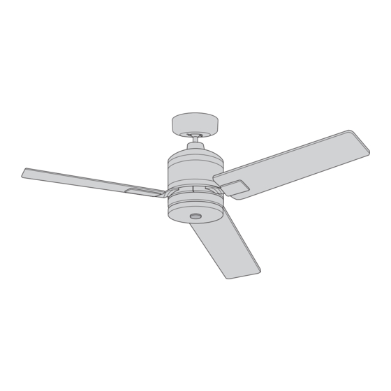
54" Ceiling Fan Owner's Manual
Questions, problems, missing parts: Before returning to the store call
Emerson Electric Customer Service - 8 a.m. - 6 p.m., Eastern, Monday-Friday
Part No. F40BP75220001
Revision: 171005
IDEAL
Model Numbers
15.8
Net Weight:
1-800-654-3545
www.emersonfans.com
CF330GBQ00
Barbeque Black with
Satin Gold Accents
CF330GSW00
Satin White with
Satin Gold Accents
Lbs.
• Español - página 29
• Français - page 57
Form No. BP7522-1
ETL Model No.: CF330
Publicité
Chapitres
Table des Matières

Manuels Connexes pour Emerson IDEAL


Sommaire des Matières pour Emerson IDEAL
- Page 1 15.8 Net Weight: Lbs. Questions, problems, missing parts: Before returning to the store call Emerson Electric Customer Service - 8 a.m. - 6 p.m., Eastern, Monday-Friday • Español - página 29 • Français - page 57 1-800-654-3545 Part No. F40BP75220001 Form No.
-
Page 2: Table Des Matières
Electric Co. Substitution of parts or accessories not 1. To avoid possible shock, be sure electricity is turned designated for use with this product by Emerson could off at the fuse box before wiring, and do not operate result in personal injury or property damage. -
Page 3: Unpacking Instructions
Ceiling Cover Emerson Electric Co. Substitution of parts or Motor Coupler Cover accessories not designated for use with this product by Emerson Electric Co. could result in personal injury LED Array or property damage. Light Kit Housing Assembly Fan Blade Flanges Fan Blades Open carton containing fan. -
Page 4: Tools Needed For Assembly
One 1/4” Blade Screwdriver One Wire Stripper Materials This Emerson Ceiling Fan may be used with the following accessory (purchased separately): SR600 Remote Control. Wiring outlet box and box connectors must be of type required by the local code. -
Page 5: Ceiling Fan Assembly
3. Ceiling Fan Assembly Flip the upper foam pad over and place on a stable SHIPPING working surface. MOTOR HUB RETAINERS (3) Remove the fan motor assembly from the protective plastic bag. Place fan motor assembly on top of the foam pad with the upper motor cover supporting the weight of the motor. - Page 6 3. Ceiling Fan Assembly (Continued) NOTE: Take care not to scratch the fan housing 1/4-20 x 1/2" OVAL HEAD SCREWS when installing the blade assemblies. (2 per assembly) Attach the Blade Flange Assembly onto the Fan Motor/ BLADE FLANGE ASSEMBLY Hub by tightening the 1/4-20 x 1/2”...
- Page 7 3. Ceiling Fan Assembly (Continued) Remove the Hanger Ball by loosening the Phillips Head GREEN GROUND WIRE Set Screw in the Hanger Ball until the Ball falls freely down the 4.5” Downrod (Figure 5). Remove the Pin from the 4.5” Downrod, then remove the Hanger Ball (Figure 5).
- Page 8 3. Ceiling Fan Assembly (Continued) Align the Clevis Pin holes in the Downrod with the holes in the Motor Coupler. Install the Clevis Pin and secure with the Hairpin Clip (Figure 8). HAIRPIN The Clevis Pin must go through the holes in the Motor CLIP MOTOR Coupler.
- Page 9 3. Ceiling Fan Assembly (Continued) 3.11 Route the two 80” Motor Wires through the Hanger Ball (Figure 11). HANGER BALL Reinstall the Hanger Ball on the Downrod as follows: DOWNROD Position the Pin through the two holes in the Downrod PHILLIPS HEAD and align the Hanger Ball so the Pin is captured in the SET SCREW...
-
Page 10: How To Hang Your Ceiling Fan
4. How to Hang Your Ceiling Fan WARNING CEILING The fan must be hung with at least 7' of clearance from floor to blades (Figure 13). WARNING To avoid possible electrical shock, be sure electricity is turned off at the main fuse box before wiring. NOTE: If you are not sure if the outlet box is grounded, contact a licensed electrician for advice, as it must be grounded for safe operation. - Page 11 4. How to Hang Your Ceiling Fan (Continued) WARNING The outlet box and joist must be securely mounted and capable of supporting at least 50 lbs. Use only a U.L. outlet box listed as “Acceptable for Fan Support of 22.7 kg. (50 lbs.) or less”. OUTLET BOX TWO SCREWS WARNING...
-
Page 12: How To Wire Your Ceiling Fan
Emerson Electric Co. Substitution of parts or accessories not designated for use with this product by Emerson Electric Co. could result in personal injury or property damage. ETL Model No.: CF330... - Page 13 5. How to Wire Your Ceiling Fan (Continued) Securely connect the Fan Motor White Wire to the Supply White (neutral) Wire using Wire Connector SUPPLY WHITE (supplied) (Figure 17). (NEUTRAL) LISTED WIRE CONNECTOR FAN MOTOR WHITE WIRE Figure 17 Securely connect the Fan Motor Black Wire to the Supply Black (hot) Wire using Wire Connector (supplied) (Figure 18).
-
Page 14: Final Assembly
6. Final Assembly Engage the Fan Motor 2-Pin Wire Connector into the 2-pin Wire Connector of the LED Array (Figure 20). The connection is complete when you hear a soft click. FAN MOTOR 2-PIN WIRE CONNECTOR LED ARRAY 2-PIN WIRE CONNECTOR LED ARRAY Figure 20 Carefully tuck all the wires and connectors into the Light... - Page 15 You have now completed the complete assembly of your new ceiling fan. Please call Emerson technical support 1-800-654-3545 if you have any questions about installation and operation of this ceiling fan.
-
Page 16: Wall Control Installation
7. Wall Control Installation Preset Memory Feature: Your Emerson receiver is Your Emerson Ceiling Fan/Light Control consists of wall equipped with a preset memory feature. If the AC mounted transmitter and a receiver located inside the supply to the receiver is powered OFF through a wall motor assembly. - Page 17 7. Wall Control Installation (Continued) This control is designed to operate only one ceiling fan NOTE: Electric connections should be in accordance with the National Electrical Codes and all Local Codes. Before starting, disconnect power to the circuit at the fuse box or circuit breaker panel.
- Page 18 7. Wall Control Installation (Continued) SINGLE-POLE INSTALLATION WARNING (One fan controlled by one wall control) Turning off wall switch is not sufficient. To avoid (See Figure 28). possible electrical shock, be sure electricity is turned off at the main fuse or circuit breaker box before wiring.
- Page 19 7. Wall Control Installation (Continued) 3-WAY INSTALLATION (One fan controlled by two different wall controls) SECONDWALL FAN/LIGHT (See Figures 29 and 30). CONTROL WALL PURCHASE CONTROL SEPARATELY WARNING GROUND GROUND Turning off wall switch is not sufficient. To avoid BLACK possible electrical shock, be sure electricity is turned off at the main fuse or circuit breaker box before LOAD...
- Page 20 7. Wall Control Installation (Continued) 3-WAY WIRING DIAGRAM: WARNING NOTE: Retrofit 3-way installations are likely to include two traveler wires between the two wall Check to see that all connections are tight and that no boxes. In new construction, only one traveler wire Is bare wires are visible at the wire connectors.
-
Page 21: Programming The Receiver Operating Frequency
8. Programming the Receiver Operating Frequency -- Important - Read This Section Carefully -- IMPORTANT: Ceiling fan blades MUST be installed before programming can begin. If programming is unsuccessful, retry the previous NOTE: If using a 3-way switch installation, ensure instructions after cycling the wall control ON/OFF switch that both wall controls are using the same switch to restart the 1 minute programming time period. -
Page 22: Using Your Ceiling Fan
9. Using Your Ceiling Fan WARNING Fan installation must be completed, including the installation of the fan blades, before testing the wall POWER control. INDICATOR LIGHT Your Wall Control has full control of your Fan and Light LIGHT AIRFLOW (Figure 31). INTENSITY DIRECTION BUTTON... -
Page 23: Maintenance
Emerson Electric Co. Substitution of parts or accessories not designated for use with this product WARNING by Emerson Electric Co. could result in personal injury or property damage. The use of any other control not specifically approved for this fan could result in fire, shock and personal injury. -
Page 24: Repair Parts
13. Repair Parts HARDWARE BAG ETL Model No.: CF330... - Page 25 13. Repair Parts Listing Model Numbers No. Description CF330BQ00 CF330GRT00 CF330SW00 CF330GBQ00 CF330GSW00 Hanger Ball Assembly, 761655-19 761655-102 761655-92 761655-19 761655-92 Consisting of: Hanger Bracket (1) — — — — — Hanger Ball (1) — — — — — 4.5” Downrod (1) —...
-
Page 26: Troubleshooting
14. Troubleshooting WARNING FOR YOUR OWN SAFETY TURN OFF POWER AT FUSE BOX OR CIRCUIT BREAKER BEFORE TROUBLESHOOTING YOUR FAN. TROUBLE PROBABLE CAUSE SUGGESTED REMEDY 1. Fan will not start. 1. Loose electrical connections in the 1. Check the electrical connections at the ceiling cover. ceiling cover. -
Page 27: Product Limited Warranty
What We Will Do To Correct Problems: If the defect is covered by this limited warranty, Emerson will repair or replace the applicable Emerson Ceiling Fan Product at no charge to You. If repair of the Emerson Ceiling Fan Product is not practical or possible within a reasonable time and no replacement Emerson Ceiling Fan Product can be provided, Emerson will refund You the actual purchase price of Your Emerson Ceiling Fan Product. - Page 28 You should record this data above and keep it in a safe place for future use. Air Comfort Products DIVISION OF EmErSON ElEctrIc cO. 8100 W. Florissant • St. louis, mO 63136 Questions, problems, missing parts: Before returning to the store call Emerson Electric Customer Service 8 a.m.
- Page 29 Peso neto: Preguntas, problemas, piezas faltantes: Antes de devolver el producto a la tienda, llame al Servicio al Cliente de Emerson Electric — 8 a.m. a 6 p.m., Hora del Este, lunes a viernes • Français – page 57 1-800-654-3545 No.
-
Page 30: Instrucciones De Seguridad
Códigos Locales. El ventilador de techo se debe conectar a tierra específicamente por Emerson Electric Co. para utilizarse con este producto. La sustitución con piezas o accesorios no diseñados por como precaución contra posibles descargas eléctricas. La Emerson para utilizarse con este producto podría causar lesiones... -
Page 31: Instrucciones De Desempaquetado
Emerson Electric Co. para utilizarse con Cubierta del acoplador del motor este producto. La sustitución con piezas o accesorios no diseñados por Emerson Electric Co. para utilizarse con este Conjunto de luces LED producto podría causar lesiones corporales o daños materiales. -
Page 32: Herramientas Necesarias Para El Ensamblaje
Este manual está diseñado para que usted pueda ensamblar, instalar, utilizar y mantener su ventilador de techo de la manera más fácil posible Este ventilador de techo Emerson viene equipado con un receptor de CC y un control de pared para el ventilador. Este sistema permite que usted Herramientas necesarias regule el control de velocidad y de iluminación de su ventilador de techo. -
Page 33: Ensamblaje Del Ventilador De Techo
3. Ensamblaje del ventilador de techo Voltee la almohadilla de espuma superior y colóquela sobre una RETENEDORES NÚCLEO DEL MOTOR SHIPPING DE ENVÍO (3) superficie de trabajo estable. MOTOR HUB RETAINERS (3) Saque el ensamblaje del motor del ventilador de la bolsa protectora de plástico. - Page 34 3. Ensamblaje del ventilador de techo (continuación) TORNILLOS DE CABEZA OVAL DE 1/4-20 x 1/2 1/4-20 x 1/2" OVAL HEAD SCREWS PULGADA (2 por ensamblaje) Nota: Las paletas tienen tornillos instalados desde la parte (2 per assembly) ENSAMBLAJE DE PALETA Y PESTAÑA superior y la parte inferior que entran en el ensamblaje del motor.
- Page 35 3. Ensamblaje del ventilador de techo (continuación) CABLE VERDE DE CONEXIÓN Retire la esfera de suspensión aflojando el tornillo de ajuste de cabeza A TIERRA GREEN GROUND WIRE Phillips ubicado en dicha esfera hasta que la misma caiga libremente PASADOR bajando por la varilla descendente de 4,5 pulgadas (Figura 5).
- Page 36 3. Ensamblaje del ventilador de techo (continuación) Alinee los agujeros para pasador de horquilla ubicados en la varilla descen - dente con los agujeros ubicados en el acoplamiento del motor. Instale el pasador de horquilla y sujételo firmemente con el clip de horquilla (Figura CLIP DE HORQUILLA...
- Page 37 3. Ensamblaje del ventilador de techo (continuación) 3.11 PASADOR Encamine los dos cables de conexión del motor de 80 pulgadas a través ESFERA DE de la esfera de suspensión (Figura 11). SUSPENSIÓN VARILLA DESCENDENTE HANGER BALL Reinstale la esfera de suspensión en la varilla descendente de la DOWNROD siguiente manera: TORNILLO DE AJUSTE...
-
Page 38: Cómo Colgar Su Ventilador De Techo
4. Cómo colgar su ventilador de techo ADVERTENCIA TECHO CEILING El ventilador se debe colgar con por lo menos 7 pies de holgura desde el piso hasta las paletas (Figura 13). ADVERTENCIA Para evitar posibles descargas eléctricas, asegúrese de que la electricidad esté... - Page 39 4. Cómo colgar su ventilador de techo (continuación) ADVERTENCIA La caja de tomacorriente y la viga deben estar montadas de manera segura y ser capaces de soportar por lo menos 50 lb. CAJA DE TOMA CORRIENTE Utilice únicamente una caja de tomacorriente U.L. listada con las OUTLET BOX DOS TORNILLOS palabras “Acceptable for Fan Support of 22.7 kg.
-
Page 40: Cómo Cablear Su Ventilador De Techo
Emerson Electric Co. para utilizarse con este producto. La sustitución con piezas o accesorios no diseñados por Emerson Electric Co. para utilizarse con este producto podría causar lesiones corporales o daños materiales. No. de modelo ETL: CF330... - Page 41 5.Cómo colgar su ventilador de techo (continuación) Conecte de manera segura el cable blanco del motor del ventilador al CABLE BLANCO cable blanco de suministro (neutro) utilizando el conector de cables DE SUMINISTRO SUPPLY WHITE suministrado (Figura 17). (NEUTRO) (NEUTRAL) CONECTOR DE CABLES LISTADO LISTED WIRE...
-
Page 42: Ensamblaje Final
6.Ensamblaje final Acople el conector de cables de 2 pines del motor del ventilador en el interior del conector de cables de 2 pines del conjunto de luces LED (Figura 20). CONECTOR DE CABLES La conexión estará completa cuando usted oiga un clic suave. DE 2 PINES DEL MOTOR FAN MOTOR DEL VENTILADOR... - Page 43 Usted ha finalizado ahora el ensamblaje completo de su nuevo ventilador de techo. Sírvase llamar a asistencia técnica de Emerson al 1-800-654-3545 si tiene alguna pregunta sobre la instalación y utilización de este ventilador de techo.
-
Page 44: Instalación Del Control De Pared
7. Instalación del control de pared Función de memoria preestablecida: Su receptor Emerson está Su control del ventilador de techo y luz Emerson consiste en un equipado con una función de memoria preestablecida. Si el suministro de transmisor montado en la pared y un receptor ubicado dentro del CA al receptor se controla a través de un interruptor de pared, al poner el... - Page 45 7. Instalación del control de pared (continuación) Este control está designado para operar sólo un ventilador de techo. NOTA: Las conexiones eléctricas deberán cumplir con los Códigos Eléctricos Nacionales y los Códigos Locales. Antes de comenzar, desconecte la alimentación al circuito en la caja de fusibles o en el panel de cortacircuitos.
- Page 46 7. Instalación del control de pared (continuación) ADVERTENCIA INSTALACIÓN UNIPOLAR (Un ventilador controlado por un control de pared) No basta con poner el interruptor de pared en la posición de (Vea la Figura 28). apagado. Para evitar una posible descarga eléctrica, asegúrese de que la electricidad esté...
- Page 47 7. Instalación del control de pared (continuación) CONTROL DE SEGUNDO CONTROL INSTALACIÓN DE 3 VÍAS PARED DEL DE PARED CORRIENTE NGR SECONDWALL VENTILADOR Y FAN/LIGHT COMPRADO (Un ventilador controlado por dos controles de pared diferentes) LA LUZ CONTROL WALL POR SEPARADO (consulte las Figuras 29 y 30.) PURCHASE CONTROL...
- Page 48 7. Instalación del control de pared (continuación) ADVERTENCIA DIAGRAMA DE CABLEADO DE 3 VÍAS: NOTA: Es probable que las instalaciones de 3 vías reconvertidas Asegúrese de que todas las conexiones estén apretadas y que no incluyan dos cables conmutables entre las dos cajas de pared. haya cables pelados visibles en los conectores de cables.
-
Page 49: Programación De La Frecuencia De Operación Del Receptor
8. Programación de la frecuencia de operación del receptor -- Importante: Lea detenidamente esta sección -- IMPORTANTE: Las paletas del ventilador de techo SE DEBEN Si la programación no tiene éxito, reintente las instrucciones que instalar antes de que pueda comenzar la programación. anteceden después de ciclar el interruptor de ENCENDIDO y NOTA: Si está... -
Page 50: Utilización De Su Ventilador De Techo
9. Utilización del ventilador de techo ADVERTENCIA Se debe completar la instalación del ventilador, incluyendo la POWER INDICADORA DE instalación de las paletas del ventilador, antes de probar el ALIMENTACIÓN INDICATOR control remoto. LIGHT SENTIDO DE BOTÓN DE El control de pared tiene control completo del ventilador y la luz CIRCULACIÓN INTENSIDAD LIGHT... -
Page 51: Mantenimiento
11. Accesorios Vea a su distribuidor local de Emerson, visite www.emersonfans.com o ADVERTENCIA consulte el Catálogo de ventiladores de techo Emerson acerca de estos accesorios: • Controles del ventilador de techo Este producto está diseñado para utilizar únicamente las piezas suministradas con este producto y/o los accesorios diseñados... - Page 52 No. de modelo ETL: CF330...
- Page 53 Números de modelo de clave Descripción CF330BQ00 CF330GRT00 CF330SW00 CF330GBQ00 CF330GSW00 Ensamblaje de la esfera de suspensión, 761655-19 761655-102 761655-92 761655-19 761655-92 que consiste en — — — — — Soporte de suspensión (1) — — — — — Esfera de suspensión (1) Varilla descendente de 4,5 pulgadas (1) 764860-BLX 764860-BLX...
-
Page 54: Resolución De Problemas
14. Resolución de problemas ADVERTENCIA PARA SU PROPIA SEGURIDAD, DESCONECTE LA ALIMENTACIÓN ELÉCTRICA EN LA CAJA DE FUSIBLES O EL CORTACIRCUITO ANTES DE RESOLVER PROBLEMAS EN SU VENTILADOR PROBLEMA CAUSA PROBABLE REMEDIO SUGERIDO 1. Conexiones eléctricas flojas en la cubierta 1. - Page 55 Ventilador de Techo Emerson sigue estando bajo garantía, sírvase retener Su recibo u otro comprobante de compra y tener esa información al alcance de la mano cuando envíe su Producto de Ventilador de Techo Emerson a Su lugar de compra o cuando llame a Servicio al Cliente de Emerson. Si Usted llama a Servicio al Cliente de Emerson, antes de Su llamada esté preparado para dar todos los números de modelo mostrados en su Producto de Ventilador de Techo Emerson.
- Page 56 DIVISION OF EmErSON ElEctrIc cO. 8100 W. Florissant • St. louis, mO 63136 Preguntas, problemas, piezas faltantes: Antes de devolver el producto a la tienda, llame al Servicio al Cliente de Emerson Electric 8 a.m. a 6 p.m., Hora del Este, lunes a viernes 1-800-654-3545 www.emersonfans.com...
- Page 57 15,8 Poids net : Questions, problèmes, pièces manquantes : Avant de retourner un produit au magasin, veuillez téléphoner au Emerson Electric Customer Service 8h00 – 18h00 (HNE) du lundi au vendredi • Español – página 29 1-800-654-3545 Pièce N° F40BP75220001 Formulaire N°...
-
Page 58: Consignes De Sécurité
Référez-vous au Code national d’électricité emploi avec celui-ci par Emerson Electric Co. Toute substitution de s’il n’existe pas de codes locaux. Le ventilateur de plafond doit pièces ou d’accessoires non conçus pour emploi avec ce produit être mis à... -
Page 59: Instructions Pour Le Déballage
4,5 po/rotule de la tige de suspension emploi avec ce produit par Emerson Electric Co. Toute substitution Monture de plafond de pièces ou d’accessoires non conçus pour emploi avec ce produit par Emerson Electric Co. -
Page 60: Outils Nécessaires Pour Le Montage
Ce mode d’emploi est conçu pour vous permettre d’assembler, d’installer, d’utiliser et d’entretenir votre ventilateur de plafond aussi facilement que possible Votre ventilateur de plafond Emerson est fourni avec un récepteur c.c. et une commande murale de ventilateur. Ce système vous permet de Outils nécessaires pour le montage... -
Page 61: Assemblage Du Ventilateur De Plafond
3. Assemblage du ventilateur de plafond PATTES DE FIXATION Retournez le coussinet de mousse supérieur et placez sur une surface MOYEU DU MOTEUR TEMPORAIRE (3) SHIPPING de travail stable. MOTOR HUB RETAINERS (3) Retirez l’ensemble de moteur du ventilateur du sac de protection en plastique. - Page 62 3. Assemblage du ventilateur de plafond (suite) VIS À TÊTE OVALE 1/4-20 x 1/2 po (2 par ensemble) 1/4-20 x 1/2" OVAL HEAD SCREWS Remarque : Faites attention de ne pas rayer le boîtier du (2 per assembly) ENSEMBLE DE BRIDE ventilateur en installant les ensembles de pales.
- Page 63 3. Assemblage du ventilateur de plafond (suite) FIL DE MISE À LA TERRE VERT Retirez la rotule de la tige de suspension en desserrant la vis de pression GREEN GROUND WIRE à tête cruciforme qui se trouve dans la rotule de la tige de suspension jusqu’à...
- Page 64 3. Assemblage du ventilateur de plafond (suite) Alignez les trous des axes à épaulement dans la tige de suspension descendante sur les trous du coupleur de moteur. Installez l’axe à épaulement et assujettissez-le au moyen de la pince de retenue (Figure 8). PINCE DE RETENUE HAIRPIN...
- Page 65 3. Assemblage du ventilateur de plafond (suite) 3.11 Acheminez les deux câbles du moteur de 80 po à travers la rotule de la ROTULE DE LA TIGE tige de suspension (Figure 11). TIGE DE SUSPENSION DESCENDANTE HANGER BALL Réinstallez la rotule de la tige de suspension sur la tige de suspension DOWNROD descendante de la façon suivante : VIS DE PRESSION...
-
Page 66: Comment Suspendre Votre Ventilateur De Plafond
4. Comment suspendre votre ventilateur de plafond AVERTISSEMENT PLAFOND CEILING Le ventilateur doit être suspendu de telle sorte que les pales se trouvent à au moins 7 pi (2 m) du sol (Figure 13). AVERTISSEMENT Pour éviter tout risque de choc électrique, assurez-vous que l’ali - mentation électrique est coupée au niveau du boîtier des fusibles avant d’effectuer le câblage. - Page 67 4. Comment suspendre votre ventilateur de plafond (suite) AVERTISSEMENT Le boîtier de prises de courant et la solive doivent être installés de façon sécurisée et être capables de supporter sans problème au BOÎTIER DE moins 50 livres (22,7 kg). Utilisez seulement des boîtiers de prises PRISES DE OUTLET BOX COURANT...
-
Page 68: Comment Effectuer Le Câblage Pour Raccorder Votre Ventilateur De Plafond
être utilisés avec ce produit par Emerson Electric Co. Toute substitution de pièces ou d’accessoires non désignés comme pouvant être utilisé avec ce produit par Emerson Electric Co. peut entraîner une blessure ou un dommage matériel. Modèle E.T.L. N° : CF330... - Page 69 5. Comment effectuer le câblage pour raccorder votre ventilateur de plafond (suite) Connectez solidement le fil blanc provenant du moteur du ventilateur au FIL D’ALIMENTATION fil blanc (neutre) de l’alimentation en utilisant un capuchon de connexion BLANC (NEUTRE) SUPPLY WHITE de fils fourni (Figure 17).
-
Page 70: Assemblage Final
6. Assemblage final Engagez le capuchon de connexion de fils à 2 broches du moteur du ventilateur dans le capuchon de connexion de fils à deux broches de la matrice de DEL (Figure 20). CAPUCHON DE CONNEXION À Lorsque la connexion aura été réalisée vous entendrez un léger déclic. FAN MOTOR 2 BROCHES DU MOTEUR DU 2-PIN WIRE CONNECTOR... - Page 71 Le montage de votre nouveau ventilateur de plafond est maintenant terminé. Veuillez contacter le support technique d’Emerson au 1-800-654-3545 si vous avez des questions concernant l’installation et le fonction nement de ce ventilateur de plafond. emersonfans.com Veuillez téléphoner au 1-800-654-3545 pour toute assistance complémentaire...
-
Page 72: Installation De La Commande Murale
7. Installation de la commande murale Fonction de mémorisation des paramètres : Votre commande de Votre commande du ventilateur de plafond/luminaire Emerson consiste ventilateur de plafond/d’éclairage Emerson comporte une fonction de en un transmetteur monté sur un mur et un récepteur qui est monté sous mémorisation des paramètres. - Page 73 7. Installation de la commande murale (suite) Cette commande n’est conçue que pour faire fonctionner un seul venti lateur de plafond. REMARQUE : Tout le câblage électrique doit être conforme aux dispositions du Code national d’électricité et des codes d’électricité locaux. Avant de commencer, coupez l’alimentation au circuit au niveau du coffret à...
- Page 74 7. Installation de la commande murale (suite) AVERTISSEMENT INSTALLATION UNIPOLAIRE (Un ventilateur commandé par une commande murale) Éteindre l’interrupteur mural ne suffit pas. Pour éviter tout choc (Voir Figure 28). électrique éventuel, assurez-vous que l’alimentation électrique est coupée au niveau du boîtier des fusibles avant d’effectuer le câblage.
- Page 75 7. Installation de la commande murale (suite) COMMANDE MURALE DU INSTALLATION AVEC DOUBLE COMMANDE SOUS VENTILATEUR/ DEUXIÈME COMMANDE SECONDWALL TENSION NOIR FAN/LIGHT LUMINAIRE MURALE ACHETÉE (Un ventilateur contrôlé depuis deux commandes murales CONTROL WALL SÉPARÉMENT différentes) (Voir Figures 29 et 30). PURCHASE CONTROL AVERTISSEMENT...
- Page 76 7. Installation de la commande murale (suite) AVERTISSEMENT SCHÉMA DE CÂBLAGE POUR INSTALLATION AVEC DOUBLE COMMANDE : Assurez-vous que toutes les connexions sont bien serrées et REMARQUE : Les installations avec double commande ayant été qu’aucun fil nu n’est visible au niveau des capuchons de connexion. modifiées incluent probablement deux fils itinérants entre les deux boîtiers muraux.
-
Page 77: Programmation De La Fréquence De Fonctionnement
8. Programmation de la fréquence de fonctionnement du récepteur -- Important - Lire attentivement cette section -- IMPORTANT : Les pales de ventilateur de plafond DOIVENT avoir Si la programmation n’a pas été couronnée de succès, recom mencez la été installées avant de commencer la programmation. procédure indiquée plus haut après avoir activé/désactivé... -
Page 78: Utilisation De Votre Ventilateur De Plafond
9. Utilisation de votre ventilateur de plafond AVERTISSEMENT Avant de tester les commandes, l’installation du ventilateur doit VOYANT INDICATEUR POWER DE MISE SOUS être terminée, y compris l’installation des pales du ventilateur. INDICATOR TENSION LIGHT BOUTON DE SENS DE CONTRÔLE DE C’est votre commande murale qui contrôle totalement votre ventilateur, CIRCULATION LIGHT... -
Page 79: Maintenance
Il est déconseillé d’utiliser des agents de nettoyage abrasifs car ceux-ci pourraient abîmer la finition de votre ventilateur de plafond. 11. Accessoires Contactez votre revendeur local de produits Emerson, allez sur le site AVERTISSEMENT www.emersonfans.com ou consultez le catalogue des ventilateurs de plafond Emerson pour ces accessoires : Ce produit est conçu pour être utilisé... - Page 80 Modèle E.T.L. N° : CF330...
- Page 81 Numéros de modèles Ref. Description CF330BQ00 CF330GRT00 CF330SW00 CF330GBQ00 CF330GSW00 Ensemble de support de suspension consistant en : 761655-19 761655-102 761655-92 761655-19 761655-92 Support de suspension (1) — — — — — Rotule de la tige de suspension (1) — —...
- Page 82 AVERTISSEMENT POUR VOTRE SÉCURITÉ, METTEZ LE COFFRET À FUSIBLES OU LE DISJONCTEUR HORS TENSION AVANT DE TENTER D’IDENTIFIER LES PROBLÈMES POUVANT AFFECTER VOTRE VENTILATEUR. PROBLÈME CAUSE PROBABLE SOLUTION PROPOSÉE 1. Connexions électriques desserrées dans la monture de 1. Inspectez les connexions électriques dans la monture de plafond. plafond.
-
Page 83: Garantie Limitée De Produit Pour Les Ventilateurs De Plafond Emerson
Ce que la garantie limitée couvre : La présente garantie limitée est offerte par Air Comfort Products, une division d’Emerson Electric Co. (« Emerson », ou « notre », « nos » ou « nous ») à l’acheteur primitif (« vous », « votre » ou «... - Page 84 DIVISION OF EmErSON ElEctrIc cO. 8100 W. Florissant • St. louis, mO 63136 Questions, problèmes, pièces manquantes : Avant de retourner un produit au magasin, veuillez téléphoner au Service à la clientèle d’Emerson Electric 8h00 – 18h00 (HNE) du lundi au vendredi 1-800-654-3545 www.emersonfans.com Conservez ce mode d’emploi pour toute utilisation future...