Table des Matières

Publicité

Les langues disponibles

Les langues disponibles

Liens rapides


INSTALLATION ET MISE EN SERVICE 
INSTALLATION AND OPERATING INSTRUCTIONS  
 
N.M.S. n° 40868051/ Ed. 3 / 10‐13 
All manuals and user guides at all-guides.com
 
NOLH 


FRANÇAIS


ENGLISH  

Publicité

Chapitres

Table des Matières
loading

Sommaire des Matières pour salmson NOLH

  • Page 1 All manuals and user guides at all-guides.com       NOLH                         INSTALLATION ET MISE EN SERVICE  FRANÇAIS           INSTALLATION AND OPERATING INSTRUCTIONS   ENGLISH    ...
  • Page 2: Installation Et Mise En Service

    All manuals and user guides at all-guides.com       NOLH                                                    FRANÇAIS     INSTALLATION ET MISE EN SERVICE ...
  • Page 3: Table Des Matières

    All manuals and user guides at all-guides.com   FRANÇAIS           Sommaire :      Généralités  ...................................... 5     A propos de ce document ..................................  5     Sécurité ....................................... 5     Pictogrammes utilisés dans la notice ..............................  5     Qualification du personnel ...................................  5     Dangers encourus en cas de non‐observation des consignes de securite ....................  5     Consignes de sécurité  ...................................  5  ...
  • Page 4 All manuals and user guides at all-guides.com   FRANÇAIS         Implantation  .......................................  1 1     7.1.1 Fondations ...................................... 11     7.1.2 Scellement  ...................................... 12     7.1.3 Positionnement du groupe  ................................ 12     7.1.4 Lignage pompe / moteur  ................................... 12     Montage et raccordement des tuyauteries ...
  • Page 5: Généralités

    Si  des  joints  de  dilatation  Si le personnel ne dispose pas des connaissances nécessaires, il y a lieu  doivent  être  montés,  vérifier  qu’ils  sont  prévus  avec  dispositif  de  de le former. Si besoin, l’utilisateur peut demander à SALMSON ou à son  blocage.  représentant  de  lui  dispenser  la  formation  appropriée.  L’exploitant  du  Le  contrôle  du  sens  de  rotation  du  moteur  ne  doit  être  effectué ...
  • Page 6: Modes D'utilisation Interdits

      La  classe  de  température  de  la  pompe  est  indiquée  sur  sa  plaque  2.9 INSTRUCTIONS  DE  SECURITE  POUR  UNE  signalétique.  Elle  est  indiquée  pour  une  température  ambiante  maximum  de  40°C  (consulter  SALMSON  pour  des  températures  UTILISATION  EN  ATMOSPHERE  ambiantes plus élevées).  ...
  • Page 7: Risque D'accumulation De Mélanges Explosifs

    Lorsque  la  pompe  est  utilisée  en  atmosphère  explosible,  T1  400°C  l’utilisateur doit vérifier régulièrement les paramètres suivants et  T2  275°C  respecter un plan de maintenance.  T3  180°C    T4  115°C  La surveillance portera particulièrement sur :  T5  80°C   La qualité de l’étanchéité d’arbre,  T6  UNIQUEMENT APRES ACCORD SALMSON   L’évolution de la température des paliers,     L’absence de signe de cavitation ou de bruit anormal,  S’il  existe  un  risque  de  fonctionnement  vanne  fermée  au     La position des vannes d’isolement et le bon fonctionnement  refoulement, il est conseillé d'installer un système de mesure de la  des vannes motorisées.  température de surface.  ...
  • Page 8: Stockage Provisoire

    Un  large  choix  de  matières  et  d’étanchéités  est  disponible  pour    doit être stockée dans un local tempéré, sec, ventilé et exempt de  répondre aux problématiques de pompage des Industriels.  vibrations. A intervalles de temps réguliers (tous les mois) faire tourner  On  trouve  les  pompes  NOLH  dans  tous  les  types  d’industries,  en  génie  l’arbre de pompe pour éviter le marquage des portées de roulement et  climatique, en adduction d’eau, pour l’irrigation, …  le  gommage  des  garnitures  mécaniques.  Refermer  l’emballage  après  manipulation de la pompe.  En  respectant  ces  conditions  de  stockage,  la  pompe  peut  être ...
  • Page 9: Sens De Rotation

    All manuals and user guides at all-guides.com   FRANÇAIS       3000  1800  1500  tr/mn  tr/mn  tr/mn  40‐315  5. 2. 2. 2 PRESSION DE SERV ICE  100‐250  150‐250  50‐315   Toutes versions : PS = 16 bar   65‐200  125‐200  Sauf pour les versions fonte des pompes :  80‐160     NOLH150‐500 : 14 bar     NOLH200‐250 à 300‐500 : 10 bar   Nombre de démarrages par heure :  Attendre  l'arrêt  complet  du  moteur  avant  de  lancer  un  nouveau   ...
  • Page 10: Position Des Brides

    All manuals and user guides at all-guides.com   FRANÇAIS         Si  un  niveau  sonore  doit  être  garanti,  seul  un  essai  réalisé  sur  le  Montage sur socle en fonte :    groupe livré peut être représentatif.  Refoulement axe z :    F  M              (N)  (N)  (N)  (N.m) ...
  • Page 11: Etendue De La Fourniture

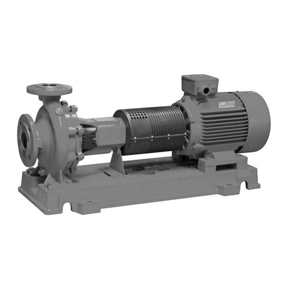
    (au  moins  X0  suivant  la  DIN  1045).  La  masse  6.2 FONCTIONNEMENT  recommandée  pour  dimensionner  le  massif  béton  doit  être  3  fois  supérieure  à  celle  du  groupe  complet.  Ceci  permet  de  déterminer  la  La  pompe  NOLH  est  une  pompe  centrifuge  à  aspiration  axiale  et  hauteur du massif en connaissant la longueur et la largeur de ce dernier  refoulement vertical.   ainsi que la masse volumique du béton utilisé. ...
  • Page 12: Scellement

    All manuals and user guides at all-guides.com   FRANÇAIS        Avant  d’intervenir  sur  les  parties  mobiles  du  groupe  motopompe  l’alimentation électrique du moteur a été coupée et condamnée.  7.1.2 SCELLEMENT    L’utilisation de chevilles chimiques est conseillée pour fixer les socles sur  Le  groupe  moto  pompe  a  été  ligné  en  usine.  Si  un  calage  très  un massif existant.  important  est  nécessaire  sous  le  moteur  ou  sous  la  pompe,  Utiliser des boulons de scellement si le massif est à réaliser (réservations ...
  • Page 13 All manuals and user guides at all-guides.com   FRANÇAIS     Si des manchons de dilatation sont utilisés, limiter leur débattement en    utilisant les tiges filetées préconisées par leur fabricant.  Clapet anti‐retour :    L’ajout d’un clapet anti‐retour au refoulement de la pompe la protègera  Deux  principes  de  montage  des  tuyauteries  d’aspiration :  pompe  en  des contre‐pressions et d’un éventuel retour de liquide lors de l’arrêt de  charge ou pompe en aspiration.  la machine.    Tuyauteries auxiliaires :  Dans la majorité des cas la pompe est montée avec une garniture simple.  Si  la  pompe  est  équipée  de  dispositifs  hydrauliques  auxiliaires,  il  faut   ...
  • Page 14: Raccordement Électrique / Mise À La Terre

    All manuals and user guides at all-guides.com   FRANÇAIS       7.3.1 RAPPEL DES COUPLAGES MOTEURS ETOILE (Y)  ET  TRIANGLE  () POUR  LES  MOTEURS  MULTI‐ TENSIONS.   Bobinage moteur multi tensions 230/400V et 400/690V :   6 bornes :      Orifices :   Vp : orifice de vidange de la pompe :    32‐125 à 50‐315 : G1/4’’  L’inversion  du  sens  de  marche  de  la  pompe  peut  être  réalisé  65‐125 à 200‐250 : G3/8’’  directement dans la boite à bornes du moteur par simple inversion entre  150‐500 à 300‐500 : G1/2’’ ...
  • Page 15: Fonctionnement Avec Un Variateur De Fréquence

    All manuals and user guides at all-guides.com   FRANÇAIS      La présence de liquide à pomper dans la tuyauterie d’aspiration et dans  7.4 FONCTIONNEMENT  AVEC  UN  VARIATEUR  le corps de pompe,  DE FREQUENCE   Le sens de rotation du moteur correct,   L’alignement de la pompe et du moteur est correct,  Si  la  pompe  doit  être  utilisée  en  vitesse  variable  ,  la  notice  du   Les niveaux et appoint de graisse ont été faits,    variateur devra être disponibles et les préconisations constructeur   La présence du(es) carter(s) de protection.  respectées.     8.2 REMPLISSAGE / DEGAZAGE  Les moteurs électriques qui équipent les pompes peuvent être raccordés ...
  • Page 16: Mise Hors Service

    All manuals and user guides at all-guides.com   FRANÇAIS      Flushing externe :  de protection, de gants, etc …) et doit appliquer les règles d’hygiène et  Vérifier  la  pression  d’alimentation  du  flushing  en  prenant  en  sécurité en vigueur dans l’Entreprise.  considération les limites suivantes :  Après arrêt, la pompe contient encore une part de produit pompé.  Pression :  Vidanger et rincer soigneusement l’hydraulique de la pompe avant  Roue diamètre 125 : P  + 0,5 bar  de commencer son démontage.  aspiration Autres diamètres de roue : P  + P  + 0,5 bar    aspiration différentielle Débit :  Des  moyens  de  levage  adaptés  doivent  être  disponibles  pour  aider  Prévoir un débit compris entre 0,1 et 0,2 m /h ...
  • Page 17: Frequences De Rempla Cement Huile

    All manuals and user guides at all-guides.com   FRANÇAIS     sont munis d’un graisseur aussi bien du côté entraînement que du côté    pompe.  Il est possible d’ajouter en accessoire un huileur à niveau constant.   Sur demande, ces pompes sont disponibles avec palier à bain d’huile.  Dès  que  le  niveau  baisse  dans  le  palier,  l’air  pénètre  dans  le    réservoir d’appoint et permet ainsi à l’huile de s’écouler dans le palier,  Préconisation pour les huiles :  ceci  tant  que  le  niveau  n’aura  pas  atteint  le  point  N  correspondant  au   ...
  • Page 18 All manuals and user guides at all-guides.com   FRANÇAIS     •  Si  nécessaire,  démonter  les  conduites  d’alimentation  de  la  garniture    mécanique.   Renouvellement des tresses :  • Si nécessaire vidanger le palier à huile et démonter le huileur à niveau  Lors  du  renouvellement  des  tresses,  les  tresses  usagés  doivent  être  constant pour qu’il ne soit pas endommagé pendant l’intervention.  enlevés  avec  précaution,  ainsi  que  la  bague  lanterne,  de  la  chambre  • Il n’est pas nécessaire de débrider le corps de pompe des tuyauteries. ...
  • Page 19 All manuals and user guides at all-guides.com   FRANÇAIS     4. Retirer le grain fixe de la garniture  mécanique 43.30 et le pion 56.10.  3. Retirer le mobile complet de la volute 10.20, retirer le joint plat 40.00,  dévisser les vis 56.00 et retirer la bague d’usure 50.20.          4. Démonter l’écrou de roue 92.20 et son hélicoïde 93.00.  Démontage du palier:  5. Démonter la roue 23.00, ôter le joint 40.03, retirer la clavette 94.01,  1. Retirer les vis 90.11, ôter le joint en V 42.20 (lubrification par graisse),  dévisser les écrous 92.02 et déposer le fond de volute 16.10.  ôter  le  couvercle  de  roulement  36.00  et  le  joint  plat  40.02.  Retirer  la    bague à lèvre 42.10 (lubrification par huile).  Exécution avec presse‐étoupe:  2. Retirer le déflecteur 50.70  1. Dévisser les écrous 92.01 et retirer les goujons 90.21.  3.  Dévisser  la  vis  90.12,  ôter  la  rondelle  frein  93.01  et  démonter  la  2. ...
  • Page 20: Remontage

    All manuals and user guides at all-guides.com   FRANÇAIS     4. En  cas de lubrification par huile,  ôter le bouchon  67.20. Si la pompe  est  équipée  d’un  huileur  à  niveau  constant  et  si  cela  n’a  pas  été  fait  avant  la  dépose  de  la  pompe,  démonter  le  huileur  à  niveau  constant  63.80.   ...
  • Page 21 All manuals and user guides at all-guides.com   FRANÇAIS         Exécution avec réchauffage :  9. 3. 2. 2 REMON TAGE PA LIERS 55 ET 65  Insérer les joints 41.22 et 41.23 dans le couvercle 16.50.  1. Préparation du palier.    2. Si l’arbre est équipé avec de nouveaux roulements, ils peuvent  être  chauffés  dans  un  bain  d’huile  à  une  température  de  80º  C  avant  assemblage.  En  premier,  positionner  le  roulement  32.11,  ensuite  le circlips 93.21 et en dernier le roulement 32.10. Assurez‐vous que les ...
  • Page 22: Moteur

    All manuals and user guides at all-guides.com   FRANÇAIS         Exécution avec garniture mécanique :    9.  Placer  le  couvercle  47.10  avec  le  grain  fixe  43.30  et  le  pion  56.10  si  Le moteur peut être équipé de paliers à roulements à billes lubrifiés à vie  nécessaire, ensuite placer le joint 40.06 et les vis 90.24.  (2Z)  comme  de  paliers  équipés  de  graisseurs  manuels.  Les  graisseurs  10. ...
  • Page 23: Incidents, Causes Et Remèdes

    All manuals and user guides at all-guides.com   FRANÇAIS     10 INCIDENTS, CAUSES ET REMEDES              Incidents  Causes  Remèdes  ‐ Contre‐pression trop importante  Démonter et nettoyer les tuyauteries de refoulement  Vérifier le point de fonctionnement  ‐ Alimentation insuffisante de la pompe  Purger l’air du corps de pompe  Remplir complètement la canalisation d’aspiration  ‐ Hauteur d’aspiration trop grande ou NPSH disponible trop faible  Vérifier les niveaux de liquide  Vérifier que les vannes coté aspiration sont ouvertes  Nettoyer les filtres  Performances trop faibles  ‐ Bague de laminage de roue trop usée  Remplacer la roue  Vérifier l’usure du corps  ‐ Mauvais sens de rotation  Inverser 2 phases dans la boite à bornes du moteur  ‐  Fuite  du  corps  de  pompe,  de  l’étanchéité  d’arbre  ou  de  la  Vérifier le serrage des boulons de fixation du fond de corps ...
  • Page 24: Recyclage Et Fin De Vie Du Produit

    All manuals and user guides at all-guides.com   FRANÇAIS       11 RECYCLAGE ET FIN DE VIE DU PRODUIT  12 PIECES DE RECHANGE  A  la  fin  de  la  vie  du  produit  ou  de  ses  composants,  les  constituants  doivent  être  recyclés  ou  éliminés  en  12.1 PLAN  EN  COUPE  ET  NOMENCLATURE  respectant les règles de protection de l'environnement et ...
  • Page 25: Plan En Coupe

    All manuals and user guides at all-guides.com   FRANÇAIS       12.1.1 PLAN EN COUPE  12. 1. 1. 1 PALIERS 25‐35‐45 :  Etanchéité par garniture mécanique :  Avec palier à roulements lubrifiés à vie :      Avec palier à roulements lubrifiés bain d’huile  :          25 ...
  • Page 26 All manuals and user guides at all-guides.com   FRANÇAIS       Montage GM simple :            Montage GM simple + quench extérieur :        Montage GM simple + réchauffage fond de corps :      Montage GM simple + flushing extérieur :          Etanchéité par presse‐étoupe à tresses :  Avec palier à roulements lubrifiés à vie :          26 ...
  • Page 27 All manuals and user guides at all-guides.com   FRANÇAIS       Avec palier à roulements lubrifiés bain d’huile  :      Montage presse‐étoupe à tresses :        27 ...
  • Page 28 All manuals and user guides at all-guides.com   FRANÇAIS       12. 1. 1. 2 PALIERS 55‐65 :  Etanchéité par garniture mécanique :  Avec palier à roulements lubrifiés à vie :      Avec palier à roulements lubrifiés bain d’huile :        28 ...
  • Page 29 All manuals and user guides at all-guides.com   FRANÇAIS       Etanchéité par presse‐étoupe à tresses :  Avec palier à roulements lubrifiés à vie :        Avec palier à roulements lubrifiés bain d’huile :        29 ...
  • Page 30: Nomenclature

    All manuals and user guides at all-guides.com   FRANÇAIS       Montage presse‐étoupe à tresses :                12. 1. 2  NOMENCLA TURE  70.30 Tuyauterie de liaison   73.10 Raccord  Repère  Désignation  73.11 Raccord flushing 10.20  Volute  90.10 Vis H  16.10  Fond de volute  90.11 Vis H  16.50  Couvercle ...
  • Page 31: Pièces De Rechange De Première Urgence

    All manuals and user guides at all-guides.com   FRANÇAIS         12.3 PIECES  DE  RECHANGE  DE  PREMIERE  12.4 PIECES  DE  RECHANGE  POUR  2  ANS  DE  URGENCE  FONCTIONNEMENT    Pour  déterminer  le  lot  de  pièces  de  rechange  en  première  Si la pompe fonctionne pour le point de fonctionnement pour lequel elle  dotation, on peut s’appuyer sur les recommandations émises dans  a été dimensionnée, elle ne nécessite que très peu de maintenance. La ...
  • Page 32: Déclaration Ce

    All manuals and user guides at all-guides.com   FRANÇAIS     13 DECLARATION CE      32 ...
  • Page 33 All manuals and user guides at all-guides.com    ...
  • Page 34 All manuals and user guides at all-guides.com       NOLH                                    ENGLISH INSTALLATION AND OPERATING INSTRUCTIONS            N.M.S. n° 4086805 / Ed. 3 / 10‐13  ...
  • Page 35 All manuals and user guides at all-guides.com                  ...
  • Page 36 All manuals and user guides at all-guides.com   ENGLISH         CON TEN TS  1  General information ........................................  5   1.1  About this document ........................................5  2  Safety ............................................  5   2.1  Symbols used in these instructions ...................................5  2.2  Personnel qualification  ......................................5  2.3  Danger in event of non‐observance of the safety instructions..........................5  2.4  Safety instructions  ........................................5  2.4.1  Safety instructions for the operator ................................... 5  2.4.2  Safety instructions for the equipment ................................ 5  2.5 ...
  • Page 37 All manuals and user guides at all-guides.com   ENGLISH       8.1  Pre‐commissioning  ........................................  1 4  8.2  Filling / Venting ........................................  1 4  8.3  Start‐up ...........................................  1 4  8.4  Running checks ........................................  1 4  8.5  Shutdown  ..........................................  1 5  9  Maintenance .........................................  1 5  9.1  General information  ........................................  1 5  9.2 ...
  • Page 38: General Information

    Qualification, knowledge evaluation and personnel supervision must be    strictly handled by the pump owner. If necessary, SALMSON or one of its  Before  checking  direction  of  rotation  make  sure  that  no  parts  representative can perform adequate training. Plant management must  could  be  ejected  from  shafts  (pins,  keys,  coupling  element  …).  ensure that contents of the operation instructions are fully understood  Several pump types will be damaged if started in the wrong direction of ...
  • Page 39: Safety Instructions For Inspection And Installation Work

    MOTOR ENCLOSURE :    Exd = flameproof  2.6 MODIFICATION  OF  EQUIPMENT  AND  Exd(e) = flameproof frame and increased safety junction box    USE OF SPARE PARTS  GAS GROUP :  Modifying  the  product  is  only  permitted  after  agreement  of  Salmson.  IIA ‐ Propane  Use  of  genuine  spare  parts  and  accessories  authorized  by  the  IIB ‐ Ethylene  manufacturer ensure safety and proper work of the pump.  IIC ‐ Hydrogen      2.7 IMPROPER USE ...
  • Page 40: Preventing Leakage

    Close  meet following requirements :   protective packing when done.  Consist of non‐sparking material (e.g brass),   If stored as described above, the pump can be stored up to 6 months.  Must be made of antistatic material,  Consult  SALMSON  for  preservative  procedure  when  a  longer  storage   Must  be  designed  in  such  a  way  that  the  rotating  parts  will  period is required.  not come in contact with any part of the guard after a choc.    2.9.8 MAINTENANCE ...
  • Page 41: Intended Use

    TEMPERATURE    Pumps with single mechanical seal arrangement : from ‐20°C to +120°C.  INTENDED USE  Pumps with gland packing arrangement : from ‐40°C to 110°C    NOLH  pumps  are  used  for  handling  of  clear  or  slightly  turbid  fluids  5. 2. 2. 1 PRESSURE  without any particle content.  All variants : maximum working pressure PS = 16 bar   Designed  according  to  EN  733  &  ISO  5199  this  pump  can  be  used  to  With the exception of following pumps with cast iron casing : ...
  • Page 42: Direction Of Rotation

    All manuals and user guides at all-guides.com   ENGLISH           Cast iron impellers :    Check  direction  of  rotation  when  motor  is  apart  (coupling  spacer  3600  3000  1800  1500 RPM  RPM  RPM  RPM  dismantled or motor not coupled to pump). If not feasible due to pump  design  (pump  fitted  with  rigid  coupling)  it  is  necessary  to  check  that  32‐125 ...
  • Page 43: Scope Of Delivery

        (N)  (N)  (N)  (N.m)  (N.m)  (N.m)  (N)  N.m)  6.1 PRODUCT INFORMATION  NOLH  pump  is  a  single  stage  PN16  volute  casing  pump  designed  for  50  600  540  660  1040  400  460  560  830  horizontal  installation.  Hydraulic  characteristics  and  dimensions  meet ...
  • Page 44: Location

    All manuals and user guides at all-guides.com   ENGLISH         INSTALLATION  AND  ELECTRICAL  Using of shrink free grout is the most efficient. Grouting ensures correct  CONNECTION  positioning of the baseframe and reduces vibrations transmission to civil  work.  Foundation  work  surface  preparation  and  leveling  of  baseframe  7.1 LOCATION  will  be  performed  in  the  state  of  the  art  and  should  be  done  before   ...
  • Page 45: Pipe Work

    All manuals and user guides at all-guides.com   ENGLISH         Negative suction head operation :  Using a straight‐edge and a caliper  :  The  suction  line  intake  should  be  located  below  the  minimum  level  of  the liquid and a strainer with non return foot valve should be installed.  The strainer should be set far enough from pit bottom to avoid excessive  suction head loss and particle intake. Ensure that there is no air intake  along suction line and avoid any air pockets creation.  Suction  lift line  should  be  laid  with a  rising  slope  towards  the  pump.  A  straight pipe (length should be 8 to 10 times the pipe nominal diameter) ...
  • Page 46: Electrical Connection / Earthing

    All manuals and user guides at all-guides.com   ENGLISH           7.3 ELECTRICAL CONNECTION / EARTHING  Impeller  dia  Check  that  motor  winding  corresponds  to  site  electric  power  supply characteristics before electrical connections are performed.  Connecting  a  230/400V  motor  on  a  400V  power  supply  or  connection  of  a  400/690V  motor  on  a  690V  power  supply  might  drive ...
  • Page 47: Y /  Starter

    All manuals and user guides at all-guides.com   ENGLISH           In every cases check :  7.3.4 Y /  STARTER :   Quality of electrical connections,   Protection devices are installed,   Auxiliary piping are connected,   Flanges connections,   Suction line and pump casing are filled with fluid,   Motor direction of rotation is correct,   Coupling alignment is correct,   Oil level was checked and greasing of ball bearings has been done,   Coupling guard is installed.        8.2 FILLING / VENTING  Grounding  of  the  complete  pumpset  will  be  performed  with  Before the very first start‐up, pump casing and suction line must be filled    special ...
  • Page 48: Shutdown

      necessary actions were taken to avoid the creation of a hazard for  State of the auxiliary systems  Depends on equipment type. See  people or environment during drainage operations.  dedicated equipment IOM  Motor  See manufacturer IOM    Shaft sealing  Weekly  Products  which  are  sent  back  to  Salmson  must  be  drained  and  Leaks from gaskets  Weekly    cleaned.  Pumped  fluid  should  be  completely  removed  from  the  Oil level and grease quantities  Daily / Weekly / Monthly  pump.  Lubricants (ball bearings)  Replacement frequency according ball  bearing type and shaft speed ...
  • Page 49: Oil Change Intervals

    All manuals and user guides at all-guides.com   ENGLISH           Greasing nipples :  Level  is  reached  when  oil  appears  in  the  elbow  of  the  fitting  (G).  (to  check, rotate tank). Then fill in the auxiliary oil tank and put back in its  vertical  position.  Always  check  that  oil  tank  is  filled  with  oil  while  the  pump is running. ...
  • Page 50 All manuals and user guides at all-guides.com   ENGLISH         9. 3. 1. 1  DISMANTLING B RA CKETS SIZES 25,35 A ND 45      Design with mechanical seal :  1. Slide out the spacer ring 50.40.  2. Remove the rotating part of the mechanical seal 43.30.  3. Remove the screws 91.40 and remove the casing cover 16.10.        1.  Mark  the  position  of  the  parts  in  relation  to  each  other  with  a  color pen or a scribing point. ...
  • Page 51 All manuals and user guides at all-guides.com   ENGLISH       Dismantling bearing bracket assembly :    1.  Remove  screws  90.11,  remove  V‐rings  42.20,  remove  the  ball  Design with stuffing box:  bearing  cover  36.00  and  flat  gasket  40.02.  Slide  out  lip  seals  42.10  1. Loosen nuts 92.01 and remove stud bolts 90.21.  (oil lubricated ball bearings).  2.  Remove  packing  gland  45.20,  tear  out  packing  rings  46.10  and  2. Remove thrower 50.70. ...
  • Page 52: Re-Assembly

    All manuals and user guides at all-guides.com   ENGLISH         Design with mechanical seal:  7. Insert the stationary part of the mechanical seal 43.30, with the  pin 56.10 if necessary, in the casing cover 16.10.    9.3.2 RE‐ASSEMBLY  Refer to tightening torques table for screws and bolts.        9. 3. 2. 1  ASSEMB LY  OF  BEARIN G  BRA CKETS  SIZES  25,35 AN D 45  1. Install spacer rings 50.50 (bracket size 25), slide the ball bearings  onto the shaft. Before assembly, heat them up to 80°C.  2.  For  oil  lubricated  ball  bearings,  press  the  lip  seal  42.10  into  bearing housing 33.00 using a tool. The lip should point towards the ...
  • Page 53 All manuals and user guides at all-guides.com   ENGLISH         7. Screw the plug 67.20, the oil level sight 64.20 and the CLO 63.80  Fasten cover 16.50 and casing cover 16.10.  (oil lubricated ball bearings).  8. Fasten foot 18.30 and slide the thrower onto the shaft 50.70.      Design with stuffing box :      9. Slide the shaft sleeve 52.40 onto the shaft.  8. Assemble bearing bracket housing 33.00 and casing cover 16.10.  10. Install one of the packing rings 46.10 in the packing housing, the  9. Install rotating part of the mechanical seal 43.30 and spacer ring  lantern  ring  45.80  and  then,  the  remaining  packing  rings  and  the  50.40.  gland 45.20.  10.  Press  the  key  94.01  in  the  shaft,  slide  impeller  23.00  onto  the  11. ...
  • Page 54: Motor

    All manuals and user guides at all-guides.com   ENGLISH       13. Add flat gasket 40.01, key 94.01, impeller 23.00 and flat gasket    40.03.  9.5 TOOLS REQUIRED  14. Tighten nut 92.20 with helicoil 93.00.  A typical range of tools that are required for pump maintenance is  15. Insert wear ring 50.20, screws 56.00 and then stud bolts 90.20.  listed below. Those tools are standard one and should be available  16.  Insert  flat  gasket  40.00  between  the  bearing  bracket  assembly  in every industrial maintenance Dpt.   and the casing 10.20. Tighten nuts 92.00.  • Wrenches to suit up to M48 nuts,  • Socket spanner up to M 48,  9.3.3 MOTOR  • Allen keys up to 10 mm,  In  order  to  ensure  an  optimum  lifetime  of  the  integrated  motor  a  • Range of screwdrivers, ...
  • Page 55: Faults, Causes And Remedies

    All manuals and user guides at all-guides.com   ENGLISH         10 FAULTS, CAUSES AND REMEDIES    Fault  Cause  Remedy ‐ Discharge pressure is too high  Open and clean discharge pipe  Check pump duty point  ‐ Pump or piping is not completely vented or filled  Vent pump casing  Fill completely suction pipe with liquid  The  pump  is  ‐ Suction lift is too high / NPSH available is too low  Check liquid levels  Check that both suction and discharge isolating valves are open  not  Clean filters  producing  ‐ Impeller laminating ring is worn  Replace impeller – Check wear in the casing  the  rated  ‐ Wrong direction of rotation  Change two phases in motor junction box  flow or head  ‐ Leakage on pump casing gaskets, on shaft sealing or on suction piping  Check the tightening of the casing cover fastening nuts ...
  • Page 56: Recycling And End Of Product Life

    All manuals and user guides at all-guides.com   ENGLISH           12 SPARE PARTS  11 RECYCLING AND END OF PRODUCT LIFE  12.1 SECTIONAL  DRAWING  AND  BILL  OF  At  the  end  of  the  service  life  of  the  equipment  or  its  parts, the relevant materials and parts should be  recycled  MATERIAL  or  disposed  of  using  an  environmentally  acceptable  The pump sectional drawing and bill of material is available ...
  • Page 57: Sectional Drawing

    All manuals and user guides at all-guides.com   ENGLISH         12.1.1 SECTIONAL DRAWING  12. 1. 1. 1 BEA RIN G BRA CKETS 25‐35‐45 :  Shaft sealing with mechanical seal :  Lifetime lubricated ball bearings :      Oil lubricated ball bearings  :          24 ...
  • Page 58 All manuals and user guides at all-guides.com   ENGLISH         Single mechanical seal arrangement  :          Single mechanical seal + external quench :        Single mechanical seal + back cover heating :      Single mechanical seal + external flushing :          Shaft sealing with stuffing box:  Lifetime lubricated ball bearings :          25 ...
  • Page 59 All manuals and user guides at all-guides.com   ENGLISH         Oil lubricated ball bearings  :      Stuffing box arrangement :        26 ...
  • Page 60 All manuals and user guides at all-guides.com   ENGLISH         12. 1. 1. 2 BEA RIN G BRA CKETS 55‐65 :  Shaft sealing with mechanical seal :  Lifetime lubricated ball bearings :      Oil lubricated ball bearings  :        27 ...
  • Page 61 All manuals and user guides at all-guides.com   ENGLISH         Shaft sealing with stuffing box:  Lifetime lubricated ball bearings :        Oil lubricated ball bearings  :        28 ...
  • Page 62: Bill Of Material

    During  warranty  period  the  use  of  genuine  pump  parts  is  50.20  Front wear ring  mandatory. It is highly recommended to do so even after warranty  50.21  Rear wear ring  period ends.  50.40  Distance ring  Your  request  for  spare  parts  can  be  sent  to  your  local  Salmson  50.50  Spacing bush  distributor  or  to  our  Spare  Parts  Department  through  our  Salmson  50.70  Thrower  Hotline.  52.30  Shaft sleeve ...
  • Page 63: Recommended Spare Parts

    All manuals and user guides at all-guides.com   ENGLISH           12.3 RECOMMENDED SPARE PARTS  12.4 RECOMMENDED  SPARE  PARTS  FOR  2    YEARS OPERATION    Spare  parts  list  can  be  erected  using  the  recommended  list    available in the DIN24296.  When  the  pump  runs  on  the  selected  duty  point,  maintenance  For ...
  • Page 64: Ec Declaration Of Conformity

    All manuals and user guides at all-guides.com   ENGLISH         13 EC DECLARATION OF CONFORMITY      31 ...
  • Page 65 ISO 14,001, respectful of the environment. This product is composed of materials in very great part which can be recycled. At the end of the lifetime, to make it eliminate in the suitable sector. SALMSON SOUTH AFRICA WILO SALMSON ARGENTINA 13, Gemini street C.U.I.T.

Table des Matières