Vetus FOLLOW-UP STEERING Manuel D'utilisation Et Instructions D'installation

Vetus FOLLOW-UP STEERING Manuel D'utilisation Et Instructions D'installation

Système de pilotage
Table des Matières

Publicité

Les langues disponibles
  • FR

Les langues disponibles

  • FRANÇAIS, page 51

Liens rapides

'Follow-Up' besturing
'Follow-Up' steering system
'Follow-Up' Steuersystem
Système de pilotage 'Follow-Up'
Mando basculati
Timonerie idrauliche con controllo a
distanza
C o pyrigh t © 2 01 2 Ve t us n .v. Sc h i e da m H o ll a n d
Bedieningshandleiding en
installatieinstructies
Operation manual and
installation instructions
Bedienungshandbuch und
Einbauanleitung
Manuel d'utilisation et
instructions d'installation
Manual de manejo y
instrucciones de instalación
Manuale per l'uso e
istruzioni per l'installazione

Publicité

Table des Matières
loading

Sommaire des Matières pour Vetus FOLLOW-UP STEERING

  • Page 1 Bedieningshandleiding en installatieinstructies Operation manual and installation instructions Bedienungshandbuch und Einbauanleitung Manuel d’utilisation et instructions d’installation Manual de manejo y instrucciones de instalación Manuale per l’uso e istruzioni per l’installazione ‘Follow-Up’ besturing ‘Follow-Up’ steering system ‘Follow-Up’ Steuersystem Système de pilotage ‘Follow-Up’ Mando basculati Timonerie idrauliche con controllo a distanza...
  • Page 2 Ce produit répond aux normes de la directive CE- 2004/108/EC (EMC), EN60945 (IEC945) Este producto cumple las normas de la directiva CE 2004/108/EC (EMC), EN60945 (IEC945) Questo prodotto è conforme alle direttive comunitarie 2004/108/EC (EMC), EN60945 (IEC945) 100901.02 Follow-Up Steering System Follow-Up Steering System...
  • Page 3: Table Des Matières

    Inleiding Deze handleiding bevat informatie over de installatie en 1 Inleiding ................ 3 de bediening van de Vetus Follow-Up besturing. Lees deze handleiding daarom zorgvuldig door alvorens de follow-up 2 Bediening ..............4 besturing te installeren, dan wel in gebruik te nemen.
  • Page 4: Bediening

    Bediening 2.1 Algemeen Bij de toelichting hoe de stuurinrichting te bedienen wordt er van uit gegaan dat de installatie volledig is uitgevoerd en de FOLLOW-UP STEERING inbedrijfstelling heeft plaatsgevonden. De volgende bedieningselementen staan ter beschikking: Hendel Met de hendelpositie wordt de stand van het roer bepaalt.
  • Page 5 Niet-plaatsgebonden bedieningseenheid Bij gebruik van de niet plaatsgebonden bedieningseenheid kunnen dezelfde handelingen worden verricht als bij de vast in de stuurstand geplaatste bedieningseenheid. HENDEL FUM0025 Aansluiten Plaats de steker in de kontaktdoos, borg de steker door de ring een kwart slag rechtsom te draaien. FUM0029 Sluit altijd de kontaktdoos af met de kap als de bedienings- eenheid niet gebruikt wordt!
  • Page 6: Inschakelen, Uitschakelen En Keuze Van De Stuurplaats

    Na het inschakelen van de voedingsspanning zal op elke stuur- stand de LED gaan knipperen, elke 1,5 seconde een korte flits. LED flitst elke 1,5 seconden FOLLOW-UP STEERING De follow-up besturing is nu ‘stand-by’. FUM0010 STAND-BY Door op een van de stuurplaatsen één keer op de ‘Stand-by’...
  • Page 7: Wisselen Van Stuurplaats (Overnemen)

    2.3 Wisselen van stuurplaats (overnemen) Stuurstand 1 (huidige actieve stuurpositie) FOLLOW-UP STEERING Druk op de niet actieve stuurplaats de ‘SET’ toets in. FOLLOW-UP STEERING FUM0006 Stuurstand 2 (passieve stuurpositie) Druk op de SET toets Stuurstand 1 FOLLOW-UP STEERING De LED zal gaan branden. Indien de stand van deze hendel overeenkomt met de stand van de hendel op de andere stuur- plaats zal de LED continue branden.
  • Page 8: Trimmen Van De Hendels

    Het is mogelijk de hendels tijdens het varen zo te kalibreren dat in de 0-stand van de hendel het schip keurig rechtuit vaart. Instellen trim FOLLOW-UP STEERING Plaats op de actieve stuurstand de hendel in de stand waarbij het schip rechtuit vaart. De hendeluitslag mag maximaal 5°...
  • Page 9: Gebruik Master-Schakelaar

    2.5 Gebruik master-schakelaar HENDEL 3 HENDEL 2 Na het inschakelen van de master-schakelaar, indien geïnstal- FOLLOW-UP STEERING leerd, kan alleen met de master-hendel (hendel1) worden gestuurd. MASTER Hendel 1 is de hendel welke is aangesloten op ingang J6. SCHAKELAAR HENDEL 1...
  • Page 10: Installatie

    - energievoorziening (5) Kies een droge plaats op geruime afstand van een warmtebron. Hoge temperaturen kunnen de werking van het apparaat nega- tief beïnvloeden. FOLLOW-UP STEERING De besturingselectronica mag nooit in het bilge- water komen te staan! J5 J4 J3 J2 Plaats de besturingselectronica op een plaats tussen de accu’s...
  • Page 11: Bedieningseenheid

    Voor aansluitschema zie 7.2. Neem in de ‘+’ kabel een hoofd- schakelaar en een zekering (20 A) op. De installatie van een hoofdschakelaar van accu naar bestu- FOLLOW-UP STEERING ringselectronica zorgt er voor dat de follow-up besturing volle- dig kan worden uitgeschakeld als het schip verlaten wordt.
  • Page 12: Stuurmachine (Of Aandrijfeenheid)

    EHP . een autopiloot of voor afleesinstrumenten, moet deze worden aangesloten zoals in deze handleiding is beschreven. Het is dus niet noodzakelijk voor een Vetus autopiloot of Voorbeeld: voor een of meerdere Vetus roerstand-afleesinstrumenten De gewenste boord-boordtijd bedraagt 15 seconden aparte roerstandgevers te installeren.
  • Page 13: Montage

    Montage Op de besturingskast van de follow-up besturing zijn aansluitin- De roerstandgever nooit buiten installeren! gen voorzien voor het roerstandsignaal voor een Vetus autopi- Installeer de roerstandgever zodanig dat de arm van de gever loot en voor de Vetus roerstandaanwijzers.
  • Page 14: Blokkeerschakelaar (Master)

    Indien dit niet geval is herplaats dan de steker (X1), zie 3.7 ‘Wijze van opstelling’, en voer de instelprocedure nogmaals uit. Bij toepassing van een Vetus Autopiloot wordt ook het signaal voor de roerstand via de besturingskast op de autopiloot aan- Tijdens het varen is fijnafstelling mogelijk voor afzonderlijk de gesloten;...
  • Page 15: Invoeren Maximale Roeruitslag

    Schakel de voedingsspanning in. De follow-up bediening moet het roer. in ‘stand-by’ staan! Maak dus geen van de handels actief en schakel niet de autopiloot in auto mode. FOLLOW-UP STEERING FOLLOW-UP STEERING Beweeg het roer met de handbesturing naar de maxi-...
  • Page 16: Calibratie Van De Nulstand Van De Hendels

    Een afwijking van de nulstand van het roer, van minder dan 10 Zet alle hendels in de midden- graden, kan tijdens het varen als volgt worden ingesteld: stand (neutraalstand), scha- FOLLOW-UP STEERING kel de voedingsspanning uit Maak bedieningseenheid nummer 1 (de hendel welke is aange- FOLLOW-UP STEERING indien deze ingeschakeld is.
  • Page 17: Technische Gegevens

    Technische gegevens Algemeen Voedingsspanning : 12 / 24 Volt gelijkspanning Opgenomen stroom in stand-by : 150 mA Besturingskast Aansluitingen voor: - Bedieningshendels : max. 3 - Blokkeerschakelaar voor master stuurstand - Autopiloot - Non-follow-up schakelaar (joy-stick) - Aan/uit schakelaar voor non-follow-up schakelaar - Roerstandgever : 5 Volt voedingsspanning Signaal...
  • Page 18: Storing Zoeken

    Storing zoeken Probleem Mogelijke oorzaak Oplossing In een van de uiterste standen wordt De roerstandgever meet een roerstand Stel de roerstandgever correct in. de stuurmachine uitgeschakeld (geen groter dan 45 graden ten opzichte van spanning meer op de motor en clutch de gecalibreerde nul.
  • Page 19 Introduction This manual contains information about the installation and 1 Introduction ..............19 operation of the Vetus Follow-Up steering system. Please read this manual carefully before installing the Follow-Up 2 Operating ..............20 steering system or taking it into service.
  • Page 20: Operating

    FUM0004 FUM0005 Push button ‘Stand-by’ - Switching the Follow-Up steering on and off - Rudder calibration, together with the ‘Set’ button Push button ‘Set’ - Changing steering position, taking over - Setting rudder trimming - Rudder calibration, together with the ‘Stand-by’...
  • Page 21 The mini handle is operated in exactly the same way as the permanently mounted handle. FUM0026 FUM0027 Push button ‘Stand-by’ - Switching the Follow-Up steering on and off - Rudder calibration, together with the ‘Set’ button 'SET' 'STAND-BY' Push button ‘Set’...
  • Page 22: Switching On And Off And Choice Of Steering Position

    2.2 Switching on and off and choice of steering position After switching on the power the LED at each steering position will begin to flash every 1.5 seconds. The Follow-Up steering LED flashes every 1.5 seconds FOLLOW-UP STEERING system is now on ‘stand-by’.
  • Page 23: Changing Steering Position (Taking Over)

    If a master switch is fitted and this has been switched on FUM2009 then a takeover procedure is not possible. Operation is then Steering position 2 only possible from handle 1. (new active steering position) Press the SET button again Follow-Up Steering System Follow-Up Steering System 100901.02...
  • Page 24: Trimming The Handles

    Press the SET button Changing steering position (taking over) and trim When the controls are taken over at another steering position the trim which has been set remains in force. 100901.02 Follow-Up Steering System Follow-Up Steering System...
  • Page 25: Use Of Master Switch

    Therefore, whenever the autopilot is switched on it will always immediately take over the controls. This will occur whether or not FUM0021 a Follow-Up or a non-Follow-Up steering system is switched on. When the autopilot is switched off the previous operating sys- tem will take over.
  • Page 26: Installation

    It is therefore essential during the installation to follow and check the points given in this manual completely. 3.2 Description of system A Follow-Up steering system consists of at least the following main parts: - Electronic control unit (1) - operating unit, for permanent installation at the (main)
  • Page 27: Operating Unit

    3.4 Operating unit Power supply, main cables The Follow-Up steering system can be connected to both a 12 Operating unit for permanent installation Volt or a 24 volt on board power supply. See wiring diagram 7.2. Fit a main switch and a fuse (20 A) in the '+' cable.
  • Page 28: Steering Drive Unit

    Connecting the steering drive unit See diagram 7.2 for the connections to the steering drive unit. The Follow-Up steering system can work with one of the follow- ing sorts of steering drive units: The current for a reversible motor * runs from the connecting...
  • Page 29 2 core cable. The green wire is about 10 m long. The other connections on the rudder feedback unit are not used! The control unit of the Follow-Up steering system is provided with connections for sending the rudder position signal to a Vetus autopilot or Vetus rudder position indicator.
  • Page 30: Blocking Switch (Master)

    (+ 12 Volt or + 24 Volt) when the autopilot is in AUTO mode! When a Vetus Autopilot is used the signal for the rudder posi- Turn the rudder and check tion is also connected via the control unit to the autopilot; see whether plug (XI) has been fitted properly;...
  • Page 31: Setting Maximum Rudder Deflection

    (with reversible motor) in order not to have the rudder shoot past the required position. Hold switch (1) on the control The Follow-Up steering system slows down the drive unit by unit pressed in for about 3 J5 J4 J3 J2 switching the reversible motor on and off rapidly (PWM).
  • Page 32: Calibration Of Zero Position Of Handles

    The boat will now begin to turn because the rudder position is now aligned to that of the handle. If the deviation in the rudder zero position is more than 10 degrees the rudder feedback unit must be set first, see 4.1. 100901.02 Follow-Up Steering System Follow-Up Steering System...
  • Page 33: Technical Details

    - Rudder position indicator : 12/24 Volt power supply Signal : 2.075 Volt +/– 0.889 V, for +/- 45º rudder angle Protection level, provided fitted in a panel : IP65 Weight : 0.65 kg Follow-Up Steering System Follow-Up Steering System 100901.02...
  • Page 34: Fault Finding

    There is no electrical connection to the Connect the rudder position indicator rudder feedback unit. correctly. 100901.02 Follow-Up Steering System Follow-Up Steering System...
  • Page 35 Inhalt Einleitung Diese Anleitung enthält Informationen zur Installation und 1 Einleitung ..............35 zur Bedienung der Follow-up-Steuerung von Vetus. Lesen Sie diese Anleitung daher sorgfältig durch, bevor Sie die 2 Bedienung ..............36 Follow-up-Steuerung installieren oder in Betrieb nehmen. 2.1 Allgemeines ............36 2.2 Ein- und Ausschalten sowie Wahl des...
  • Page 36: Bedienung

    Bedienung 2.1 Allgemeines Bei der Erläuterung dazu, wie die Steuereinrichtung zu bedie- nen ist, wird davon ausgegangen, dass die Installation voll- FOLLOW-UP STEERING ständig durchgeführt worden ist und die Inbetriebnahme statt- gefunden hat. Die folgenden Bedienelemente stehen zur Verfügung: Hebel Mit der Hebelposition lässt sich der Stand des Ruders bestim-...
  • Page 37 Nicht-platzgebundene Bedienungseinheit Bei Benutzung der nicht-platzgebundenen Bedienungseinheit lassen sich dieselben Handlungen vornehmen wie bei der fest am Steuerstand angebrachten Bedienungseinheit. HEBEL FUM3025 Anschließen Stecker in die Steckdose stecken, Stecker durch den Ring sichern und um eine Vierteldrehung nach rechts drehen. Schließen Sie die Steckdose immer mit der Kappe ab, wenn FUM0029 die Bedienungseinheit nicht benutzt wird!
  • Page 38: Ein- Und Ausschalten Sowie Wahl Des Steuerplatzes

    2.2 Ein- und Ausschalten sowie Wahl des Steuerplatzes Nach dem Einschalten der Versorgungsspannung muss an jedem Steuerstand die LED-Anzeige aufblinken, und zwar alle LED-Anzeige blinkt FOLLOW-UP STEERING 1,5 Sekunden mit einem kurzen Aufleuchten. Die Follow-up- alle 1,5 Sekunden Steuerung befindet sich jetzt im ‘Standby’. FUM3010 STAND-BY Indem man an einem der Steuerplätze ein Mal auf den...
  • Page 39: Wechseln Des Steuerplatzes (Übernehmen)

    2.3 Wechseln des Steuerplatzes Steuerstand 1 (aktuell aktive Steuerposition) FOLLOW-UP STEERING (Übernehmen) Am nicht-aktiven Steuerplatz die ‘SET’-Taste drücken. FOLLOW-UP STEERING FUM3006 Steuerstand 2 (passive Steuerposition) Auf die SET-Taste drücken Steuerstand 1 Die LED-Anzeige leuchtet auf. Falls die Stellung dieses Hebels FOLLOW-UP STEERING mit dem Stand des Hebels auf dem anderen Steuerstand über-...
  • Page 40: Trimmen Der Hebel

    Es ist möglich, die Hebel während der Fahrt so zu kalibrieren, dass in der 0-Stellung des Hebels das Schiff tadellos gerade- aus fährt. FOLLOW-UP STEERING Einstellung Trimmung Stellen Sie am aktiven Steuerstand den Hebel in die Stellung, in der das Schiff geradeaus fährt.
  • Page 41: Benutzung Master-Schalter

    2.5 Benutzung Master-Schalter HEBEL 3 HEBEL 2 Nach dem Einschalten des Master-Schalters, falls installiert, FOLLOW-UP STEERING kann nur mit dem Master-Hebel (Hebel 1) gesteuert werden. Hebel 1 ist der Hebel, der am Eingang J6 angeschlossen ist. MASTER- SCHALTER HEBEL 1...
  • Page 42: Installation

    - Energieversorgung (5) Anbringung Suchen Sie einen trockenen Platz in ziemlicher Entfernung von einer Wärmequelle aus. Hohe Temperaturen können sich nega- FOLLOW-UP STEERING tiv auf die Arbeitsweise des Gerätes auswirken. Die Steuerungselektronik darf nie im Bilgenwasser J5 J4 J3 J2...
  • Page 43: Bedienungseinheit

    Die Follow-up-Steuereinrichtung lässt sich sowohl an ein 12 Bedienungseinheit zur festen Montage Volt- als auch an ein 24 Volt-Bordnetz anschließen. Für den Schaltplan siehe 7.2 Nehmen Sie in das ‚+’-Kabel einen Hauptschalter und eine FOLLOW-UP STEERING Sicherung (20 A) auf. Installation eines Hauptschalters Akku Steuerungselektronik sorgt dafür, dass die Follow-up-Steuerung...
  • Page 44: Steuermaschine (Oder Antriebseinheit)

    Anleitung angegeben. Teilen Sie den Inhalt des Zylinders durch die gewünschte Bord- Es ist also nicht erforderlich, für einen Vetus-Autopiloten oder Bordzeit, um die Leistung der zu wählenden EHP zu bestimmen. für einen oder mehrere Vetus-Ruderstand-Ableseinstrumente gesonderte Ruderstandsgeber zu installieren.
  • Page 45: Montage

    Montage Den Ruderstandsgeber nie draußen installieren! Auf dem Steuerungskasten der Follow-up-Steuerung sind Anschlüsse für das Ruderstandssignal für einen Vetus-Autopiloten Den Ruderstandsgeber so installieren, dass der Arm des Gebers genau dem Helmstock folgt. und für die Vetus-Ruderstandsanzeigen vorhanden.
  • Page 46: Blockierschalter (Master)

    Autopilot im AUTO-Modus befindet! Während der Fahrt ist Feinabstimmung getrennt möglich für die Follow-up-Steuerung, einen Autopiloten und Ruderstandsables Bei Anwendung eines Vetus-Autopiloten wird auch das Signal einstrumente. Für die Follow-up-Steuerung siehe 4.5. für den Ruderstand über den Steuerungskasten des Autopiloten Schlagen Sie für die Feinabstimmung eines Autopiloten und...
  • Page 47: Eingabe Maximaler Ruderausschlag

    Versorgungsspannung einschalten. Die Follow-up-Bedienung Ruders kontrollieren muss sich in ’Standby’ befinden! Aktivieren Sie daher also keinen Hebel und schalten Sie auch nicht den Autopiloten in den Auto-Modus. FOLLOW-UP STEERING FOLLOW-UP STEERING Bringen Sie das Ruder mit der Handsteuerung in den maximal gewünschten...
  • Page 48: Kalibrierung Des Nullstands Der Hebel

    4.6 Kalibrierung des Nullstands des Alle Hebel in Mittelstellung Ruders (Nullstand) stellen, FOLLOW-UP STEERING Eine Abweichung des Nullstands des Ruders von weniger als FOLLOW-UP STEERING Versorgungsspannung aus- 10 Grad lässt sich während der Fahrt wie folgt einstellen: schalten, falls diese einge- schaltet sein sollte.
  • Page 49: Technische Daten

    Technische Daten Allgemeines Versorgungsspannung : 12 / 24 Volt Gleichspannung Aufgenommener Strom im Standby : 150 mA Steuerungskasten Anschlüsse für: Bedienungshebel : max. 3 Blockierschalter für Master-Steuerstand Autopilot Nicht-Follow-up-Schalter (Joystick) Ein-/Aus-Schalter für Nicht-Follow-up-Schalter Ruderstandsgeber : 5 Volt Versorgungsspannung Signal : 2,5 Volt -/+ 0,342 V, bei +/- 45º Ruderausschlag Umkehrmotor oder Magnetventile : max.
  • Page 50: Fehlersuche

    Fehlersuche Problem Mögliche Ursache Lösung In einem der äußersten Stellungen wird Der Ruderstandsgeber misst einen Ruderstandsgeber korrekt einstellen die Steuermaschine ausgeschaltet (keine Ruderstand von mehr als 45 Grad im Spannung mehr auf dem Motor und Hinblick auf die kalibrierte Null. Schaltkupplung ausgegangen) Der Summer lässt während des Betriebs Der Ruderstandsgeber hat 5 Sekunden...
  • Page 51 Le présent manuel contient les informations sur l’instal- 1 Introduction ..............51 lation et la commande du système de pilotage Follow-Up Vetus. Lire attentivement ce manuel avant d’installer ou 2 Commande ..............52 d’utiliser le système de pilotage follow-up. 2.1 Généralités ............52 2.2 Branchement, débranchement et choix de...
  • Page 52: Commande

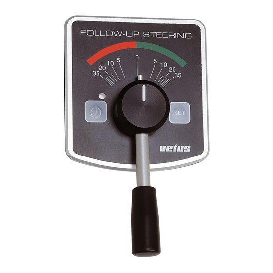
    2.1 Généralités Les explications sur la manière d’actionner le dispositif de pilo- tage partent du principe que l’installation est terminée et que la FOLLOW-UP STEERING mise en service a eu lieu. L’utilisateur dispose des éléments de commande suivants : Levier La position de levier détermine la position du gouvernail.
  • Page 53: Unité De Commande Non Liée À Un Emplacement Spécifique

    Unité de commande non liée à un emplacement spé- cifique L’unité de commande non liée à un emplacement spécifique permet d’exécuter les mêmes opérations qu’avec un dispositif LEVIER fixé dans l’emplacement de pilotage. FUM4025 Raccordement Introduire la fiche dans la prise de courant, verrouiller la fiche en tournant l’anneau d’un quart de tour vers la droite.
  • Page 54: Branchement, Débranchement Et Choix De L'emplacement De Pilotage

    Après le branchement de la tension d’alimentation, la LED de chaque emplacement de pilotage se met à clignoter toutes les LED clignotant toutes FOLLOW-UP STEERING 1,5 secondes. Le système de pilotage follow-up est maintenant les 1,5 secondes « stand-by ».
  • Page 55: Changement D'emplacement De Pilotage (Reprise)

    2.3 Changement d’emplacement de Emplacement de pilotage 1 (position de pilotage active actuelle) FOLLOW-UP STEERING pilotage (reprise) Appuyer sur la touche « SET » sur l’emplacement de pilotage non actif. FOLLOW-UP STEERING FUM4006 Emplacement de pilotage 2 (position de pilotage passive)
  • Page 56: Equilibrage Des Leviers

    Les leviers peuvent être calibrés pendant la navigation de telle manière que le bateau continue de se déplacer en ligne droite lorsque le levier est en position 0. FOLLOW-UP STEERING Réglage de l’équilibrage Sur l’emplacement de pilotage actif, placer le levier dans la position assurant un déplacement en ligne droite du bateau.
  • Page 57: Utilisation De L'interrupteur Master

    2.5 Utilisation de l’interrupteur master LEVIER 3 LEVIER 2 Après avoir branché l’interrupteur master, si présent, vous ne FOLLOW-UP STEERING pouvez piloter qu’avec le levier master (levier1). Le levier 1 est le levier qui est raccordé à l’entrée J6. INTERRUPTEUR...
  • Page 58: Installation

    Choisir un endroit sec à bonne distance d’une source de cha- leur. Les températures élevées peuvent perturber le fonctionne- ment de l’appareil. FOLLOW-UP STEERING L’électronique de commande ne doit jamais entrer en contact avec l’eau de cale ! J5 J4 J3 J2 Placer l’électronique de commande entre les batteries et le...
  • Page 59: Unité De Commande

    Le système de pilotage follow-up peut être raccordé sur un réseau de bord de 12 ou de 24 volts. Pour le schéma de raccordement, voir 7.2. FOLLOW-UP STEERING Incorporer un interrupteur principal et un fusible (20 A) dans le câble « + ».
  • Page 60: Dispositif De Pilotage (Ou D'entraînement)

    Consulter à cet effet la fiche technique remise par le fournisseur être acheté séparément. de la direction hydraulique. Si un indicateur de position de gouvernail Vetus a déjà été ins- Diviser la capacité du cylindre par le temps bord-bord souhaité tallé, pour un pilote automatique ou des instruments de lecture, pour déterminer la capacité...
  • Page 61 Vetus et pour les instruments Monter l’indicateur de position de gouvernail de façon à ce de lecture de position de gouvernail Vetus.
  • Page 62: Interrupteur De Blocage (Master)

    Pour le système de pilotage follow-up, voir 4.5. Si l’on utilise un pilote automatique Vetus, le signal pour la Consulter le manuel afférent pour le réglage plus précis du position de gouvernail est aussi raccordé via l’armoire de com- pilote automatique et des instruments de lecture de position de mande sur le pilote automatique ;...
  • Page 63: Introduction Du Déplacement Maximal Du Gouvernail

    être sur « stand-by » ! N’activez donc aucun levier gouvernail. et ne mettez pas le pilote automatique en mode auto. Déplacer le gouvernail avec la commande manuelle jus- FOLLOW-UP STEERING FOLLOW-UP STEERING qu’au déplacement maximal souhaité à tribord. FUM0034 FUM0035 Appuyer sur l’interrupteur (1)
  • Page 64: Calibrage De La Position Zéro Des Leviers

    Mettre tous les leviers dans Une déviation de la position zéro du gouvernail de moins de 10 la position centrale (position degrés peut être ajustée comme suit pendant la navigation : FOLLOW-UP STEERING FOLLOW-UP STEERING neutre), débrancher la tension d’alimentation si celle-ci est Faire en sorte que l’unité...
  • Page 65: Spécifications Techniques

    Spécifications techniques Généralités Tension d’alimentation : 12 / 24 volts continus Courant absorbé en stand-by : 150 mA Armoire de commande Raccordements pour : - Leviers de commande : max. 3 - Interrupteur de blocage pour emplacement de pilotage master - Pilote automatique - Interrupteur Non-follow-up (manche à...
  • Page 66: Recherche De Pannes

    Recherche de pannes Problème Cause probable Solution Le dispositif de pilotage se débranche L’indicateur de position du gouvernail Régler correctement l’indicateur de posi- dans l’une des positions extrêmes (il n’y mesure une position de gouvernail supé- tion de gouvernail. a plus de tension sur le moteur et les rieure à...
  • Page 67 Este manual contiene información sobre la instalación y el manejo del sistema de dirección de seguimiento “Follow- 2 Manejo ................. 68 Up” de Vetus. Primero léanse atentamente estas instruccio- 2.1 En general............. 68 nes antes de instalar el sistema de dirección de seguimien- 2.2 Activar, desactivar y selección del...
  • Page 68: Manejo

    En las instrucciones de manejo del sistema de mando se parte de la base que la instalación se ha ejecutado completamente y FOLLOW-UP STEERING que la puesta en funcionamiento ya ha tenido lugar. Quedan a su disposición los siguientes elementos de manejo: Palanca Con la posición de la palanca se determina la posición del...
  • Page 69 Unidad de manejo no sujeta a determinado lugar Al hacer uso de la unidad de manejo no sujeta a determinado lugar se pueden realizar las mismas operaciones como con la unidad de manejo instalada fijamente en la posición de gobierno. PALANCA FUM5025 Conectar...
  • Page 70: Activar, Desactivar Y Selección Del Puesto De Mando

    Una vez activada la tensión de alimentación empezará a des- tellar en cada posición de gobierno el LED, emitirá un breve LED destella cada FOLLOW-UP STEERING flechazo cada 1,5 segundo. El sistema de dirección de segui- 1,5 segundos miento ahora está ‘en posición de espera’.
  • Page 71: Cambio De Puesto De Mando (Pasar A Otro)

    2.3 Cambio de puesto de mando (pasar Posición de gobierno 1 (posición de gobierno activo actual) FOLLOW-UP STEERING de uno a otro) En el puesto de mando no activo, pulse la tecla ‘SET’. FOLLOW-UP STEERING FUM5006 Posición de gobierno 2 (posición de gobierno pasivo)
  • Page 72: Calibrar Las Palancas

    Es posible calibrar las palancas durante la navegación de forma tal que en la posición 0 de la palanca la navegación seguirá un rumbo perfectamente hacia delante. FOLLOW-UP STEERING Ajustar la desviación En la posición de gobierno activa ponga la palanca en la posi- ción en la que la navegación siga un rumbo todo recto.
  • Page 73: Uso Del Interruptor Principal

    2.5 Uso del interruptor principal PALANCA 3 PALANCA 2 Después de activar el interruptor principal, si instalado, sólo se FOLLOW-UP STEERING puede gobernar con la palanca principal (palanca1). Palanca 1 es la palanca que está conectada en la toma J6. INTERRUPTOR...
  • Page 74: Instalación

    - fuente de energía (5) Ubicación Elija un lugar seco a amplia distancia de una fuente de calor. Las temperaturas altas pueden afectar negativamente el funcio- FOLLOW-UP STEERING namiento del aparato. ¡La electrónica de gobierno nunca puede quedar J5 J4 J3 J2...
  • Page 75: Unidad De Manejo

    El sistema de dirección de seguimiento se puede conectar tanto en una red de a bordo de 12 Voltios como de 24 Voltios. Para el esquema de conexión véase 7.2. FOLLOW-UP STEERING Incluya en el cable positivo ‘+’ un interruptor principal y un fusible (20 A).
  • Page 76: Máquina De Dirección (O Unidad De Propulsión)

    BEH con motor de funcionamiento continuo y timón (Vetus art. RFU1718). válvulas magnéticas). Si ya está instalada una unidad de reacción del timón Vetus, Determine el contenido del cilindro que ya está instalado o que para un piloto automático o para instrumentos de lectura, es se va a instalar.
  • Page 77: Modo De Instalación

    Monte la unidad de reacción del timón de forma tal que timón para un piloto automático Vetus y para los indicadores el brazo del indicador se mueva en el mismo plano que la de posición del timón Vetus.
  • Page 78: Interruptor De Bloqueo (Principal)

    Para la dirección de seguimiento, véase 4.5. Al aplicar un Piloto automático Vetus también la señal para la Consulte las instrucciones correspondientes para el ajuste posición del timón se conecta en el piloto automático a través preciso de un piloto automático e instrumentos de lectura de la...
  • Page 79: Introducir La Orientación Máxima Del Timón

    Desactive la tensión de alimentación, si se mueve el timón Mueva el timón con el mando manual a la posición a estri- bor deseada máxima. FOLLOW-UP STEERING FOLLOW-UP STEERING Presione y mantenga presio- nado durante unos 3 segun- FUM0034...
  • Page 80: Calibración De La Posición Cero De Las Palancas

    Ponga todas las palancas en Una desviación de la posición cero del timón, inferior a 10 gra- la posición media (posición dos, se puede ajustar durante la navegación como sigue: FOLLOW-UP STEERING FOLLOW-UP STEERING neutra), desactive la tensión de alimentación si estuviera Haga de la unidad de manejo número 1 (la palanca que está...
  • Page 81: Especificaciones Técnicas

    Especificaciones técnicas General Tensión de alimentación : 12 / 24 Voltios corriente continua Corriente absorbida en posición de espera : 150 mA Caja de mandos Conexiones para: - Palancas de control : max. 3 - Interruptor de bloqueo para la posición de gobierno principal - Piloto automático - Interruptor de no-seguimiento (palanca de control orientable) - Interruptor de activación/desactivación para interruptor...
  • Page 82: Identificación Y Solución De Defectos

    Identificación de defectos Problema Posible Causa Solución En una de las posiciones más extremas La unidad de reacción del timón mide Ajuste correctamente la unidad de reac- se desactiva la máquina de dirección (ya una posición de timón mayor a 45 gra- ción del timón.
  • Page 83 Le presenti istruzioni contengono informazioni circa l’in- 1 Introduzione ............... 83 stallazione e l’uso della timoneria idraulica con controllo a distanza Vetus. Leggete attentamente le istruzioni prima di 2 Uso ................84 installare e mettere in funzione la timoneria idraulica con 2.1 Generale ..............
  • Page 84: Uso

    Le istruzioni per l’uso del sistema di governo partono dal pre- supposto che l’installazione e la messa in funzione siano state correttamente effettuate. FOLLOW-UP STEERING Il sistema è dotato dei seguenti elementi di comando: Leva La posizione della leva determina la posizione del timone.
  • Page 85 Unità di comando mobili Con le unità di comando mobili possono essere effettuate le stesse operazioni che vengono effettuate con le unità di comando montate fisse in postazione di comando. HANDLE FUM2025 Allacciamento Inserite la spina nella presa di alimentazione e boccate la spina ruotando l’apposito anello un quarto di giro a destra.
  • Page 86: Accensione, Spegnimento E Scelta Della Postazione Di Comando

    Una volta alimentato il sistema, il LED di ciascuna postazione di comando comincia a lampeggiare con un’intermittenza di 1,5 LED a intermittenza FOLLOW-UP STEERING secondi. Il controllo a distanza si trova ora in ‘stand by’. ogni 1,5 secondi FUM6010 STAND-BY Premendo una volta sul pulsante ‘Stand by’...
  • Page 87: Cambio Di Postazione Di Comando (Passaggio Di Comando)

    2.3 Cambio di postazione di comando Postazione di comando 1 (postazione di comando FOLLOW-UP STEERING (passaggio di comando) attualmente attiva) Premere il pulsante ‘SET’ della postazione di comando non attiva. FOLLOW-UP STEERING FUM6006 Postazione di comando 2 Premere il (postazione di comando passiva)
  • Page 88: Regolazione Delle Leve

    Le leve possono essere calibrate in modo tale che l’imbarcazio- ne proceda perfettamente dritta quando la leva di comando si trova nella sua posizione neutra (0). FOLLOW-UP STEERING Impostazione dell’assetto Nella postazione di comando attiva, mettere la leva nella posi- zione in cui l’imbarcazione procede diritta.
  • Page 89: Uso Dell'interruttore Master

    2.5 Uso dell’interruttore master LEVA 3 LEVA 2 Una volta premuto l’interruttore master, se installato, l’imbar- FOLLOW-UP STEERING cazione può essere governata solo mediante la leva master (leva 1). INTERRUTTORE La leva 1 è la leva collegata all’ingresso J6. MASTER...
  • Page 90: Installazione

    Scegliete una posizione asciutta e sufficientemente distante da - batteria (5) eventuali fonti di calore. Temperature elevate possono influire negativamente sul funzionamento del dispositivo. FOLLOW-UP STEERING Il microprocessore non deve mai venire a contatto con l’acqua di sentina! J5 J4 J3 J2...
  • Page 91: Unità Di Comando

    La timoneria idraulica con controllo a distanza può essere col- legata a tensioni di bordo a 12V e a 24V. Per i collegamenti si rimanda allo schema 7.2. FOLLOW-UP STEERING Dotate il cavo ‘+’ di un interruttore principale ed una resistenza (20 A).
  • Page 92: Macchina Del Timone (O Trasmissione)

    Qualora fosse già installato un trasmettitore della posizione Dividete il volume del cilindro per la durata desiderata della del timone Vetus, per un pilota automatico o per gli strumenti corsa per determinare la portata della EHP da scegliere. di lettura, esso deve essere collegato secondo le indicazioni riportate nel presente manuale.
  • Page 93 Installate il trasmettitore della posizione del timone in modo tale segnalatore di posizione del timone, per un pilota automatico che il braccio dell’indicatore segua accuratamente la barra del Vetus e per gli indicatori dell’angolo di barra Vetus. timone. Non collegate mai direttamente un pilota automati- Montate il trasmettitore della posizione del timone in modo co o gli indicatori dell’angolo di barra sul trasmetti-...
  • Page 94: Interruttore Di Bloccaggio (Master)

    Durante la navigazione è possibile effettuare una regolazione fine della timoneria idraulica con controllo a distanza, del pilota In caso di installazione di un pilota automatico Vetus, anche il automatico e degli strumenti di indicazione dell’angolo di barra, segnalatore di posizione del timone viene collegato al pilota indipendentemente gli uni dagli altri.
  • Page 95: Impostazione Dell'angolo Massimo Del Timone

    Dare corrente all’impianto. Il comando a distanza deve trovarsi timone. in ‘stand by’! Pertanto, non attivate nessuna leva e mettete il pilota automatico in modo auto. FOLLOW-UP STEERING FOLLOW-UP STEERING Muovete il timone con il comando manuale, fino a raggiungere l’angolo mas-...
  • Page 96: Calibrazione Della Posizione Neutra Delle Leve

    4.6 Calibrazione della posizione neutra del delle leve timone Posizionate tutte le leve nella Una deviazione dalla posizione neutra del timone, inferiore a 10 FOLLOW-UP STEERING posizione mediana (posizione gradi, può essere regolata durante la navigazione, procedendo FOLLOW-UP STEERING neutra) e togliete l’alimenta- come segue: zione, se inserita.
  • Page 97: Dati Tecnici

    Dati tecnici Generale Tensione di alimentazione : 12 / 24 Volt CC Corrente assorbita in stand by : 150 mA Pannello del microprocessore Collegamenti per: - Leve di comando : max. 3 - Interruttore di bloccaggio per postazione master - Pilota automatico - Interruttore del comando a Joy-stick - Interruttore acceso/spento per interruttore di comando a Joy-stick...
  • Page 98: Ricerca Guasti

    Ricerca guasti Problema Possibile causa Rimedio In una delle posizioni limite la macchina Il trasmettitore della posizione del timone Regolare correttamente il trasmettitore del timone viene spenta (mancanza di misura un angolo maggiore di 45 gradi della posizione del timone. tensione sul motore e sulle uscite clu- rispetto allo zero calibrato.
  • Page 99 Aantekeningen Notizen Anotaciones Remarks Remarques Note Follow-Up Steering System Follow-Up Steering System 100901.02...
  • Page 100: Schaltpläne Schémas De Raccordement

    - Aan/uit schakelaar non-follow-up bediening (joy-stick) 8 Non-Follow-Up operating (joystick) 8 Non-follow-up bediening (joy-stick) 9 Autopilot 9 Autopiloot 10 Rudder feedback unit (RFU1718) 10 Roerstandgever (RFU1718) 11 Rudder position indicator display instrument 11 Roerstandaanwijsinstrument 100901.02 Follow-Up Steering System Follow-Up Steering System...
  • Page 101 8 Système de pilotage non-follow-up (manche à balai) 10 Trasmettitore della posizione del timone (RFU1718) 9 Pilote automatique 11 Strumento di indicazione dell’angolo di barra. 10 Indicateur de position du gouvernail (RFU1718) 11 Instrument de lecture de position de gouvernail Follow-Up Steering System Follow-Up Steering System 100901.02...
  • Page 102 9 Accu 9 Battery 9 Akku 10 Zekering volgens EHP specificatie 10 Fuse according to EHP specification 10 Sicherung nach EHP-Spezifikation 11 Hoofdschakelaar 11 Main switch 11 Hauptschalter 12 Cilinder 12 Cylinder 12 Zylinder 100901.02 Follow-Up Steering System Follow-Up Steering System...
  • Page 103 9 Batería 9 Batteria 10 Fusible selon spécification EHP 10 Fusible según especificación BEH 10 Resistenza secondo specifiche EHP 11 Interrupteur principal 11 Interruptor principal 11 Interruttore principale 12 Cylindre 12 Cilindro 12 Cilindro Follow-Up Steering System Follow-Up Steering System 100901.02...
  • Page 104 Blanco Bianco Brun Marrón Marrone Bruin Brown Braun Groen Green Grün Vert Verde Verde Geel Yellow Gelb Jaune Amarillo Giallo Bedieningseenheden Control units Bedienungseinheiten Unités de commande Unidades de manejo Unità di comando 100901.02 Follow-Up Steering System Follow-Up Steering System...
  • Page 105 Bruin Brown Braun Brun Marrón Marrone + 5 V Bruin + 5 V Follow-Up Steering System Roerstandgever Ruderstandsgeber Unidad de reacción del timón Rudder feedback unit Indicateur de position du gouvernail Trasmettitore della posizione del timone Follow-Up Steering System 100901.02...
  • Page 106 Nicht-Follow-up-Schalter (Joystick) Interrupteur Non-Follow-up (Manche à balai) J5 J4 J3 J2 Interruptor de no-seguimiento (Palanca de control FUM0044 orientable) Interruttore del comando a Joy-stick – – Zoemer Buzzer Summer Vibreur Zumbador Segnalatore acustico 100901.02 Follow-Up Steering System Follow-Up Steering System...
  • Page 107 RPI1810 RPI1800 + 12 V + 12 V + 12 V Roerstandaanwijzers Rudder position indicators Ruderstandsanzeiger Instruments de lecture de position de gouvernail Indicadores de la posición del timón Indicatori dell’angolo di barra Follow-Up Steering System Follow-Up Steering System 100901.02...
  • Page 108 Autopiloot piloot aangesloten Autopilot with output suitable for reversible Where the Vetus Autopilot is used the signal for the rud- motor, including Vetus Autopilot der position is also connected to the autopilot via the con- trol unit Autopilot muss einen für Umkehrmotoren geeig-...
  • Page 109 12 Bleu (Masse analogique) 12 Azul (Masa análoga) 12 Blu (Massa analogica) 13 Vert (Signal indicateur de position 13 Verde (Señal unidad de reacción 13 Verde (Segnalatore di posizione du gouvernail) del timón) timone) Follow-Up Steering System Follow-Up Steering System 100901.02...
  • Page 110: Dimensiones Principales

    Hoofdafmetingen Overall dimensions Hauptabmessungen Dimensions principales Dimensiones principales Dimensioni principali max. 35 FOLLOW-UP STEERING ø 6(4x) FUM0056 FUM0052 FUM0059 FUM0058 max. 300 cm 100901.02 Follow-Up Steering System Follow-Up Steering System...
  • Page 111 Aantekeningen Notizen Anotaciones Remarks Remarques Note Follow-Up Steering System Follow-Up Steering System 100901.02...
  • Page 112 FOKKERSTRAAT 3125 SCHIEDAM HOLLAND TEL.: 4377700 TELEFAX: +31 10 4372673 - 4621286 - E-MAIL: sales@vetus.nl - INTERNET: http://www.vetus.com Printed in the Netherlands 100901.02 (I.FU) 2012-08...

Table des Matières