
Manuels Connexes pour Lenze CANopen E82ZAFUC001


Sommaire des Matières pour Lenze CANopen E82ZAFUC001
- Page 1 EDK82ZAFUC−001 .RJg Montageanleitung Mounting Instructions Instructions de montage CANopen E82ZAFUC001 Funktionsmodul Function module Module de fonction...
- Page 2 Lesen Sie zuerst diese Anleitung und die Dokumentation zum Grundgerät, bevor Sie mit den Arbeiten beginnen! Beachten Sie die enthaltenen Sicherheitshinweise. Please read these instructions and the documentation of the standard device before you start working! Observe the safety instructions given therein! Lire le présent fascicule et la documentation relative à...
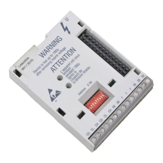
- Page 3 E82ZAFUC002B 0Abb. 0Tab. 0 Pos. Beschreibung Ausführliche Information ^ 35 Verbindungsstatus zum Grundgerät (zweifarbige LED, grün/rot) Status der CANopen−Kommunikation (zweifarbige LED, grün/rot) ^ 31 DIP−Schalter zur Konfiguration der Knotenadresse ("Address") Übertragungsrate ("Bd") ^ 14 Klemmenleiste X3, Anschluss für CANopen Reglersperre (CINH) externe Spannungsversorgung ^ 12 Typenschild...
- Page 4 Inhalt Über diese Dokumentation ......... . Verwendete Konventionen .
- Page 5 Softwarestand CANopen E82ZAFUC001 Zielgruppe Diese Dokumentation wendet sich an Personen, die das beschriebene Produkt nach Projekt- vorgabe installieren und in Betrieb nehmen. Tipp! Informationen und Hilfsmittel rund um die Lenze−Produkte finden Sie im Download−Bereich unter www.lenze.com EDK82ZAFUC−001 DE/EN/FR 5.0...
- Page 6 Über diese Dokumentation Verwendete Konventionen Verwendete Konventionen Diese Dokumentation verwendet folgende Konventionen zur Unterscheidung verschiede- ner Arten von Information: Informationsart Auszeichnung Beispiele/Hinweise Zahlenschreibweise Dezimaltrennzeichen Punkt Es wird generell der Dezimalpunkt verwendet. Beispiel: 1234.56 Symbole Seitenverweis Verweis auf eine andere Seite mit zu- sätzlichen Informationen Beispiel: 16 = siehe Seite 16...
- Page 7 Über diese Dokumentation Verwendete Hinweise Verwendete Hinweise Um auf Gefahren und wichtige Informationen hinzuweisen, werden in dieser Dokumenta- tion folgende Piktogramme und Signalwörter verwendet: Sicherheitshinweise Aufbau der Sicherheitshinweise: Gefahr! (kennzeichnet die Art und die Schwere der Gefahr) Hinweistext (beschreibt die Gefahr und gibt Hinweise, wie sie vermieden werden kann) Piktogramm und Signalwort Bedeutung Gefahr von Personenschäden durch gefährliche elektri-...
- Page 8 Über diese Dokumentation Verwendete Hinweise Anwendungshinweise Piktogramm und Signalwort Bedeutung Wichtiger Hinweis für die störungsfreie Funktion Hinweis! Nützlicher Tipp für die einfache Handhabung Tipp! Verweis auf andere Dokumentation EDK82ZAFUC−001 DE/EN/FR 5.0...
- Page 9 Sicherheitshinweise Sicherheitshinweise Gefahr! Unsachgemäßer Umgang mit dem Funktionsmodul und dem Grundgerät kann schwere Personenschäden und Sachschäden verursachen. Beachten Sie die in der Dokumentation zum Grundgerät enthaltenen Sicherheitshinweise und Restgefahren. Stop! Elektrostatische Entladung Durch elektrostatische Entladung können elektronische Bauteile innerhalb des Funkionsmoduls beschädigt oder zerstört werden.
- Page 10 Produktbeschreibung Funktion Produktbeschreibung Funktion Das Funktionsmodul koppelt Lenze Frequenzumrichter an das Kommunikationssystem CANopen. Bestimmungsgemäße Verwendung Das Funktionsmodul ... ƒ ist eine Zubehör−Baugruppe, die mit folgenden Lenze−Grundgeräten eingesetzt werden kann: Produktreihe Gerätebezeichnung ab Hardwarestand Frequenzumrichter 8200 vector Vx14 8200 motec Vx14...
- Page 11 Produktbeschreibung Lieferumfang Lieferumfang E82ZAFUC002B / E82ZAFX028 Pos. Lieferumfang Funktionsmodul E82ZAFUC001 Montageanleitung Schraubendreher Zwei Busabschluss−Widerstände (je 120 Klebestreifen EDK82ZAFUC−001 DE/EN/FR 5.0...
- Page 12 Produktbeschreibung Identifikation Identifikation ‚ƒ ‚ƒ A22 APPLICATION APPLICATION 010 / 3A22 010 / 3A22 Type Id.-No. Prod.-No. Ser.-No. E82AF000P0B201XX E82ZAFX005 ‚ ƒ E82ZAF Produktreihe CANopen Gerätegeneration Variante: Standard−Ausführung Hardwarestand Softwarestand EDK82ZAFUC−001 DE/EN/FR 5.0...
- Page 13 IEC/EN 60721−3−1 1K3 (−25 ... +60 °C) Transport IEC/EN 60721−3−2 2K3 (−25 ... +70 °C) Betrieb Entsprechend der Daten des verwendeten Lenze Grundgerätes (siehe Dokumentation des Grundgerätes). Verschmutzung EN 61800−5−1 Verschmutzungsgrad 2 Schutzart IP20 (Berührschutz nach NEMA 250 Typ 1)
- Page 14 Technische Daten Schutzisolierung Schutzisolierung Isolierung zwischen Bus und ... Art der Isolierung (nach EN 61800−5−1) Leistungsteil – 8200 vector Verstärkte Isolierung – 8200 motec Verstärkte Isolierung – starttec Verstärkte Isolierung Betriebsisolierung Bezugserde / PE (X3/7) Betriebsisolierung externer Versorgung (X3/59) Betriebsisolierung Versorgung für CINH (X3/20) Betriebsisolierung Reglersperre, CINH (X3/28)
- Page 15 Technische Daten Abmessungen Abmessungen E82ZAFU002D 51 mm 64 mm 15 mm EDK82ZAFUC−001 DE/EN/FR 5.0...
- Page 16 Mechanische Installation Mechanische Installation Folgen Sie zur mechanischen Installation des Funktionsmoduls den Hinweisen in der Mon- tageanleitung des Grundgerätes. Die Montageanleitung des Grundgerätes ... ƒ ist Teil des Lieferumfangs und liegt jedem Gerät bei. ƒ gibt Hinweise, um Beschädigungen durch unsachgemäße Behandlung zu vermeiden. ƒ...
- Page 17 Elektrische Installation EMV−gerechte Verdrahtung Elektrische Installation EMV−gerechte Verdrahtung Für eine EMV−gerechte Verdrahtung beachten Sie folgende Punkte: Hinweis! Steuer−/Datenleitungen getrennt von Motorleitungen verlegen. ƒ Legen Sie die Schirme der Steuer−/Datenleitungen bei digitalen Signalen ƒ beidseitig auf. Zur Vermeidung von Potenzialdifferenzen zwischen den ƒ...
- Page 18 Elektrische Installation Verdrahtung mit einem Leitrechner Verdrahtung mit einem Leitrechner In folgender Abbildung ist die CAN−Leitungsführung am Funktionsmodul dargestellt: 8200 vector 8200 vector SPS/PC E82ZAFUC001 E82ZAFUC001 HIGH E82ZAFU014 Frequenzumrichter der Reihe 8200 vector/motec mit aufgesteckten Funktionsmodulen und der CANopen−Master kommunizieren über CANopen. Spezifikation des Übertragungskabels Wir empfehlen CAN−Kabel nach ISO 11898−2 zu verwenden: CAN−Kabel nach ISO 11898−2...
- Page 19 Elektrische Installation Busleitungslänge Busleitungslänge Hinweis! Halten Sie die zulässigen Leitungslängen unbedingt ein! 1. Überprüfen Sie die Einhaltung der Gesamt−Leitungslänge in Tab. 1. Durch die Übertragungsrate ist die Gesamt−Leitungslänge festgelegt. Übertragungsrate [kBit/s] Gesamt−Leitungslänge [m] 8000 3900 1500 1000 Tab. 1 Gesamt−Leitungslänge 2.
- Page 20 Bestimmung der max. Leitungslänge der kleinere Wert verwendet werden. Beispiel: Auswahlhilfe Vorgaben (gemäß Kabel−Spezifikation ^ 18) 0.5 mm Leitungsquerschnitt: Teilnehmeranzahl: Lenze−Repeater, Typ 2176 (Leitungsreduzierung: 30 m) Repeater: Halten Sie unter Berücksichtigung der Vorgaben folgende Leitungslängen / Anzahl Repea- ter ein: Übertragungsrate [kBit/s] 1000 Max. Leitungslänge [m] 8000...
- Page 21 Ohne Repeater−Einsatz ist die zu realisierende Leitungslänge von 1500 m nicht möglich. Es muss ein Repeater nach 360 m (Pkt. 2.) eingesetzt werden. Ergebnis Verwendet wird der Lenze−Repeater, Typ 2176 (Leitungsreduzierung: 30 m) Berechnung der max. Leitungslänge für das – erste Segment: 360 m –...
- Page 22 Elektrische Installation Spannungsversorgung Spannungsversorgung Versorgung der Reglersperre (CINH) über die interne Spannungsquelle (X3/20) GND1 GND2 20 V E82ZAFU001 Versorgung der Reglersperre (CINH) über die externe Spannungsquelle GND1 GND2 20 V E82ZAFU002 EDK82ZAFUC−001 DE/EN/FR 5.0...
- Page 23 Elektrische Installation Spannungsversorgung Versorgung des Funktionmoduls und der Reglersperre (CINH) über die externe Spannungsquelle GND1 GND2 20 V E82ZAFU003 Für den Betrieb notwendige Mindestverdrahtung EDK82ZAFUC−001 DE/EN/FR 5.0...
- Page 24 Elektrische Installation Belegung der Anschlussklemmen Belegung der Anschlussklemmen Klemme Bezeichnung Funktion / Pegel CAN−GND Bezugspotenzial für CAN CAN−LOW CAN−Datenleitung (LOW) CAN−HIGH CAN−Datenleitung (HIGH) Externe DC−Spannungsversorgung des Funktionsmoduls: 24 V DC (21.4 V DC − 0 % ... 28.8 V DC + 0 %) Stromaufnahme an 24 V DC: 80 mA Beim Durchschleifen der Versorgungsspannung zu anderen Busteilnehmern über die Klemme 59 darf der fließende Strom max.
- Page 25 Elektrische Installation Leitungsquerschnitte und Schraubenanzugsmomente Leitungsquerschnitte und Schraubenanzugsmomente Bereich Werte Elektrischer Anschluss Klemmenleiste mit Schraubanschluss Anschlussmöglichkeiten starr: 1.5 mm (AWG 16) flexibel: ohne Aderendhülse 1.0 mm (AWG 18) mit Aderendhülse, ohne Kunststoffhülse 0.5 mm (AWG 20) mit Aderendhülse, mit Kunststoffhülse 0.5 mm (AWG 20) Anzugsmoment...
- Page 26 Busabschluss−Widerstand abgeschlossen ist. Hinweis! Eine allgemeingültige Beschreibung der Inbetriebnahme von Funktionsmodulen mit CANopen−Kommunikationsprofil, über eines der dazu zahlreich am Markt erhältlichen Programme, ist Rahmen dieser Dokumentation nicht möglich. Ein solches Programm ist nicht Teil des Lenze Lieferumfangs. EDK82ZAFUC−001 DE/EN/FR 5.0...
- Page 27 Inbetriebnahme Inbetriebnahmeschritte Inbetriebnahmeschritte Hinweis! Halten Sie unbedingt die Einstellreihenfolge ein. Schritt Beschreibung Ausführliche Information ^ 30 Leitsystem (CANopen−Master) für die Kommunikation mit dem Funk- tionsmodul konfigurieren. Grundgerät über Klemme 28 (CINH) sperren. Dokumentation des Grundgerä- Klemme 28 auf LOW−Pegel legen. Das Grundgerät kann später über den Bus gesperrt und freigege- ben werden.
- Page 28 Inbetriebnahme Inbetriebnahmeschritte Schritt Beschreibung Ausführliche Information ^ 31 A Knotenadresse einstellen über ... – C1509 oder – DIP−Schalter S1 ... S7. Übertragungsrate einstellen über ... – C1516 oder – DIP−Schalter S8 ... S10. Gelten die Einstellungen über Codestelle (DIP−Schalter S1 ... S7 = OFF), so muss nach einem Parametersatz−Transfer die Knotenadresse und Übertragungsrate neu zugewiesen werden.
- Page 29 Inbetriebnahme Inbetriebnahmeschritte Schritt Beschreibung Ausführliche Information Das Leitsystem bewirkt den Wechsel in den Zustand "Operational" beim Funktionsmodul. ^ 35 Reaktion Zweifarbige LED "Verbindungsstatus zum Grundgerät" ( ) leuch- tet konstant grün. Sie können über die PDOs (z. B. Statuswort) lesen oder Sollwerte (z.
- Page 30 Zur Kommunikation mit dem Funktionsmodul muss zunächst das Leitsystem konfiguriert werden. Einstellungen am CANopen−Master Zur Projektierung des CAN−Busses muss in der Projektierungssoftware des CANopen− Masters die Gerätebeschreibungsdatei (EDS−Datei) der Kommunikationsbaugruppe einge- lesen werden. Die EDS−Datei kann im Download−Bereich unter http://www.Lenze.com heruntergeladen werden. EDK82ZAFUC−001 DE/EN/FR 5.0...
- Page 31 Wird ein DIP−Schalter in Stellung ON gesetzt, wird die Knotenadresse (C1509)/Übertragungsrate (C1516) mit den entsprechenden Werten der Schalterstellungen überschrieben. Einstellungen über Codestellen DIP−Schalter S1 ... S7 = OFF (Lenze−Einstellung) ƒ Die Knotenadresse über C1509 einstellen. ƒ Die Übertragungsrate über C1516 einstellen.
- Page 32 Inbetriebnahme Knotenadresse und Übertragungsrate einstellen Knotenadresse einstellen Abb. 1 Adressierung über DIP−Schalter Hinweis! Die Knotenadressen bei mehreren vernetzten Antriebsreglern müssen sich voneinander unterscheiden. ƒ Die Knotenadressen bei mehreren vernetzten CAN−Teilnehmern müssen sich voneinander unterscheiden. ƒ Alle in Stellung ON befindlichen Schalter (1 ... 7) ergeben in der Summe der Wertigkeiten die gewünschte Knotenadresse.
- Page 33 Inbetriebnahme Knotenadresse und Übertragungsrate einstellen Übertragungsrate einstellen Abb. 2 Einstellen der Übertragungsrate Hinweis! Die Übertragungsrate muss bei allen Antriebsreglern und dem Leitrechner identisch eingestellt werden. Übertragungsrate [kBit/s] 1000 Automatische Erkennung Automatische Erkennung der Übertragungsrate Hinweis! Die automatische Übertragungsratenerkennung ist nur möglich, wenn schon andere Teilnehmer über den CAN−Bus fehlerfrei Telegramme senden: Nach dem Einschalten oder einem "Reset Node"...
- Page 34 Nach einer Störung (z. B. kurzzeitiger Netzausfall) ist der Wiederanlauf eines Antriebs in manchen Fällen unerwünscht oder sogar unzulässig. In C0142 lässt sich das Wiederanlaufverhalten des Antriebsreglers einstellen: C0142 = 0 (Lenze−Einstellung) ƒ – Der Antriebsregler bleibt gesperrt (auch wenn die Störung nicht mehr aktiv ist).
- Page 35 Das Funktionsmodul ist mit Spannung versorgt und hat eine Ver- bindung zum Grundgerät. blinkt Fehler im Funktionsmodul: Parameter wurde auf Lenze−Einstellung zurückgesetzt. CANopen Betrieb ist möglich. Schwerer Fehler im Funktionsmodul: CANopen Betrieb ist nicht möglich. EDK82ZAFUC−001 DE/EN/FR 5.0...
- Page 36 Diagnose LED−Statusanzeigen Pos. Farbe / Zustand Beschreibung Verbindung zum Master nicht aufgebaut. grün CANopen Zustand (" ") CANopen Fehler (" ") : Bus Off blinkt schnell (flackern) Automatische Übertragungsratenerkennung ist aktiv. blinkt (grün) im 0.2 s−Takt : Pre−Operational, : keine blinkt (grün) im 0.2 s−Takt : Pre−Operational, : Warning Limit reached...
- Page 37 E82ZAFUC002B 0Fig. 0Tab. 0 Pos. Description Detailed information ^ 69 Connection status to the standard device (two−coloured LED, green/red) Status of CANopen communication (two−coloured LED, green/red) ^ 65 DIP switches for configurationof the Node address ("Address") Baud rate ("Bd") ^ 48 Terminal strip X3, connection for CANopen Controller inhibit (CINH)
- Page 38 Contents About this documentation ......... . . Conventions used .
- Page 39 This documentation includes ... ƒ Safety instructions which you must observe in any case; ƒ Data about the versions of Lenze standard devices to be used; ƒ Information about the mechanical and electrical installation of the function module; ƒ Information about the commissioning of the function module;...
- Page 40 About this documentation Conventions used Conventions used This documentation uses the following conventions to distinguish between different types of information: Type of information Identification Examples/notes Numbers Decimal separator Point The decimal point is used throughout this documentation. Example: 1234.56 Symbols Page reference Reference to another page with additional information...
- Page 41 About this documentation Notes used Notes used The following pictographs and signal words are used in this documentation to indicate dangers and important information: Safety instructions Structure of safety instructions: Danger! (characterises the type and severity of danger) Note (describes the danger and gives information about how to prevent dangerous situations) Pictograph and signal word Meaning...
- Page 42 About this documentation Notes used Application notes Pictograph and signal word Meaning Important note to ensure troublefree operation Note! Useful tip for simple handling Tip! Reference to another documentation EDK82ZAFUC−001 DE/EN/FR 5.0...
- Page 43 Safety instructions Safety instructions Danger! Inappropriate handling of the function module and the standard device can cause serious injuries to persons and damage to material assets. Observe the safety instructions and residual hazards included in the documentation of the standard device. Stop! Electrostatic discharge Electronic components within the function module can be damaged or...
- Page 44 The function module connects Lenze frequency inverters to the CANopen communication system. Application as directed The function module ... ƒ is an accessory module for use in conjunction with the following Lenze standard devices: Product range Device designation From hardware version...
- Page 45 Product description Scope of supply Scope of supply E82ZAFUC002B / E82ZAFX028 Pos. Scope of supply E82ZAFUC001 function module Mounting Instructions Screwdriver Two bus terminating resistors (120 each) Adhesive tape EDK82ZAFUC−001 DE/EN/FR 5.0...
- Page 46 Product description Identification Identification ‚ƒ ‚ƒ A22 APPLICATION APPLICATION 010 / 3A22 010 / 3A22 Type Id.-No. Prod.-No. Ser.-No. E82AF000P0B201XX E82ZAFX005 ‚ ƒ E82ZAF Product series CANopen Version Variant: standard version Hardware version Software version EDK82ZAFUC−001 DE/EN/FR 5.0...
- Page 47 1K3 (−25 to +60 °C) Transport IEC/EN 60721−3−2 2K3 (−25 to +70 °C) Operation Corresponding to the data of the Lenze standard device used (see documentation of the standard device). Pollution EN 61800−5−1 Degree of pollution 2 Degree of protection IP20 (protection against accidental contact according to NEMA 250 type 1) EDK82ZAFUC−001 DE/EN/FR 5.0...
- Page 48 Technical data Protective insulation Protective insulation Insulation between bus and ... Type of insulation (in accordance with EN 61800−5−1) Power stage – 8200 vector Reinforced insulation – 8200 motec Reinforced insulation – starttec Reinforced insulation Functional insulation Reference earth / PE (X3/7) Functional insulation External supply (X3/59) Functional insulation...
- Page 49 Technical data Dimensions Dimensions E82ZAFU002D 51 mm 64 mm 15 mm EDK82ZAFUC−001 DE/EN/FR 5.0...
- Page 50 Mechanical installation Mechanical installation Follow the notes given in the Mounting Instructions for the standard device for the mechanical installation of the function module. The Mounting Instructions for the standard device ... ƒ are part of the scope of supply and are enclosed with each device. ƒ...
- Page 51 Electrical installation EMC−compliant wiring Electrical installation EMC−compliant wiring For wiring according to EMC requirements observe the following points: Note! Separate control cables/data lines from motor cables. ƒ Connect the shields of control cables/data lines at both ends in the case of ƒ...
- Page 52 Electrical installation Wiring to a host Wiring to a host The following illustration shows the CAN cable routing on the function module: 8200 vector 8200 vector SPS/PC E82ZAFUC001 E82ZAFUC001 HIGH E82ZAFU014 Frequency inverters of the 8200 vector/motec series with plugged−in function modules communicate with the CANopen master via CANopen.
- Page 53 Electrical installation Bus cable length Bus cable length Note! It is absolutely necessary to comply with the permissible cable lengths! 1. Check the compliance with the total cable length in Tab. 1. The total cable length is defined by the baud rate. Baud rate [kbps] Total cable length [m] 8000...
- Page 54 (according to cable specification ^ 52) 0.5 mm Cable cross−section: Number of nodes connected: Lenze repeater, type 2176 (cable reduction: 30 m) Repeater: For the above selections the following cable lengths / number of repeaters must be observed: Baud rate [kbps] 1000 Max.
- Page 55 It is not possible to use a cable length of 1500 m without applying a repeater. After 360 m (item 2.), a repeater must be installed. Result The Lenze repeater, type 2176 (cable reduction: 30 m), is used Calculation of the max. cable length for the – first segment: 360 m –...
- Page 56 Electrical installation Voltage supply Voltage supply Controller inhibit (CINH) supply via internal voltage source (X3/20) GND1 GND2 20 V E82ZAFU001 Controller inhibit (CINH) supply via external voltage source GND1 GND2 20 V E82ZAFU002 EDK82ZAFUC−001 DE/EN/FR 5.0...
- Page 57 Electrical installation Voltage supply Function module and controller inhibit (CINH) supply via external voltage source GND1 GND2 20 V E82ZAFU003 Minimum wiring required for operation EDK82ZAFUC−001 DE/EN/FR 5.0...
- Page 58 Electrical installation Assignment of the terminals Assignment of the terminals Terminal Designation Function / level CAN−GND Reference potential for CAN CAN−LOW CAN data line (LOW) CAN−HIGH CAN data line (HIGH) External DC voltage supply for the function module: 24 V DC (21.4 V DC − 0 % ... 28.8 V DC + 0 %) Current consumption at 24 V DC: 80 mA The current flowing to other nodes via clamp 59 when looping through the supply voltage must not exceed 3 A.
- Page 59 Electrical installation Cable cross−sections and screw−tightening torques Cable cross−sections and screw−tightening torques Range Values Electrical connection Terminal strip with screw connection Possible connections rigid: 1.5 mm (AWG 16) flexible: without wire end ferrule 1.0 mm (AWG 18) with wire end ferrule, without plastic sleeve 0.5 mm (AWG 20) with wire end ferrule, with plastic sleeve...
- Page 60 A generally applicable description for commissioning function modules with a CANopen communication profile using one of the numerous programs available on the market cannot be provided within the scope of this documentation. Such a program is not included in Lenze’s scope of supply. EDK82ZAFUC−001 DE/EN/FR 5.0...
- Page 61 Commissioning Commissioning steps Commissioning steps Note! Do not change the setting sequence. Step Description Detailed information ^ 64 Configure master system (CANopen master) for communication with the function module. Inhibit standard device via terminal 28 (CINH). Documentation of the standard Set terminal 28 to LOW level.
- Page 62 Commissioning Commissioning steps Step Description Detailed information ^ 65 A Set node address via ... – C1509 or – DIP switches S1 ... S7. Set baud rate via ... – C1516 or – DIP switches S8 ... S10. If the settings via code apply (DIP switches S1 ... S7 = OFF), the node address and baud rate have to be newly assigned after a parameter set transfer.
- Page 63 Commissioning Commissioning steps Step Description Detailed information The master system effects the change to the "Operational" state at the function module. ^ 69 Response The two−colored LED "Connection status to the standard device" ) is constantly illuminated with a green light. You can read (e.g.
- Page 64 For configuring the CAN bus, the device description file (EDS file) of the communication module has to be imported in the configuring software of the CANopen master. The EDS file can be downloaded in the download area at http://www.Lenze.com. EDK82ZAFUC−001 DE/EN/FR 5.0...
- Page 65 If a DIP switch is set to ON, the node address (C1509)/baud rate (C1516) will be overwritten with the corresponding values of the switch positions. Settings via codes DIP switches S1 ... S7 = OFF (Lenze setting) ƒ Set the node address via C1509. ƒ...
- Page 66 Commissioning Setting node address and baud rate Node address setting Fig. 1 Address assignment via DIP switch Note! If several controllers are connected to the network, the node addresses must differ from each other. ƒ If several devices are connected to the CAN network, the node addresses must differ from each other.
- Page 67 Commissioning Setting node address and baud rate Baud rate setting Fig. 2 Baud rate setting Note! The baud rate must be set to the same value for all controllers and the master computer. Baud rate [kbps] 1000 Automatic recognition Automatic recognition of the baud rate Note! The baud rate can only be recognised automatically if other nodes are already sending telegrams via the CAN bus without errors:...
- Page 68 − in some cases − even not allowed. The restart behaviour of the controller can be set in C0142: C0142 = 0 (Lenze setting) ƒ – The controller remains inhibited (even if the fault is no longer active).
- Page 69 The function module is supplied with voltage and has a connection to the standard device. blinking Error in the function module: Parameter was reset to Lenze setting. CANopen operation is possible. Fatal error in the function module: CANopen operation is not possible.
- Page 70 Diagnostics LED status displays Pos. Colour / status Description Connection to master not established. green CANopen status (" ") CANopen fault (" ") : bus off blinking fast (jittering) Automatic baud rate recognition is active. blinking (green) every 0.2 s : pre−operational, : none blinking (green) every 0.2 s...
- Page 71 E82ZAFUC002B 0Fig. 0Tab. 0 Pos. Description Informations détaillées ^ 103 Etat de la liaison avec l’appareil de base (LED bicolore verte et rouge) Etat de la communication du bus CANopen (LED bicolore verte et rouge) ^ 99 Interrupteurs DIP pour la configuration de l’adresse de nœud ("Address") ;...
- Page 72 Sommaire Présentation du document ......... . . Conventions utilisées .
- Page 73 La présente documentation contient ... ƒ des consignes de sécurité à respecter impérativement ; ƒ les valeurs indiquées concernant les versions des appareils de base Lenze à utiliser ; ƒ des informations sur l’installation mécanique et électrique du module de fonction ;...
- Page 74 Présentation du document Conventions utilisées Conventions utilisées Pour distinguer les différents types d’information, cette documentation utilise les conventions suivantes : Type d’information Aperçu Exemples/remarques Représentation des chiffres Séparateur décimal Point Le point décimal est généralement utilisé. Exemple : 1234.56 Pictogrammes Renvoi à...
- Page 75 Présentation du document Consignes utilisées Consignes utilisées Pour indiquer des risques et des informations importantes, la présente documentation utilise les mots et pictogrammes suivants : Consignes de sécurité Présentation des consignes de sécurité Danger ! (Le pictogramme indique le type de risque.) Explication (L’explication décrit le risque et les moyens de l’éviter.) Pictogramme et mot associé...
- Page 76 Présentation du document Consignes utilisées Consignes d’utilisation Pictogramme et mot associé Explication Remarque Remarque importante pour assurer un fonctionnement correct importante ! Conseil utile pour faciliter la mise en œuvre Conseil ! Renvoi à une autre documentation EDK82ZAFUC−001 DE/EN/FR 5.0...
- Page 77 Consignes de sécurité Consignes de sécurité Danger ! Toute utilisation contre−indiquée du module de fonction et de l’appareil de base peut entraîner des blessures graves et des dommages matériels. Tenir compte des consignes de sécurité et des dangers résiduels énoncés dans la documentation de l’appareil de base.
- Page 78 Description du produit Fonction Description du produit Fonction Le module de fonction est utilisé pour coupler les convertisseurs de fréquence Lenze avec le système de communication CANopen. Utilisation conforme à la fonction Le module de fonction ... ƒ est un module additionnel qui peut être utilisé avec les appareils de base suivants : Série d’appareils...
- Page 79 Description du produit Équipement livré Équipement livré> E82ZAFUC002B / E82ZAFX028 Pos. Equipement livré Module de fonction E82ZAFUC001 Instructions de montage Tournevis Deux résistances d’extrémité de bus (de 120 chacune) Bande autocollante EDK82ZAFUC−001 DE/EN/FR 5.0...
- Page 80 Description du produit Identification Identification ‚ƒ ‚ƒ A22 APPLICATION APPLICATION 010 / 3A22 010 / 3A22 Type Id.-No. Prod.-No. Ser.-No. E82AF000P0B201XX E82ZAFX005 ‚ ƒ E82ZAF Série d’appareils CANopen Génération d’appareils Variante : version standard Version matérielle Version logicielle EDK82ZAFUC−001 DE/EN/FR 5.0...
- Page 81 CEI/EN 60721−3−1 1K3 (−25 ... +60 °C) Transport CEI/EN 60721−3−2 2K3 (−25 ... +70 °C) Fonctionnement Conformément aux données de l’appareil de base Lenze utilisé (voir la documentation de l’appareil de base). Pollution ambiante EN 61800−5−1 Degré de pollution 2 admissible...
- Page 82 Spécifications techniques Isolement de protection Isolement de protection Isolement entre le bus et... Type d’isolement (selon EN 61800−5−1) Partie puissance – 8200 vector Isolement renforcé – 8200 motec Isolement renforcé – starttec Isolement renforcé Isolement fonctionnel Point de terre / PE (X3/7) Isolement fonctionnel Alimentation externe (X3/59) Isolement fonctionnel...
- Page 83 Spécifications techniques Encombrements Encombrements E82ZAFU002D 51 mm 64 mm 15 mm EDK82ZAFUC−001 DE/EN/FR 5.0...
- Page 84 Installation mécanique Installation mécanique Pour l’installation mécanique du module de fonction, suivre les consignes fournies dans les instructions de montage de l’appareil de base. Les instructions de montage de l’appareil de base ... ƒ font partie de la livraison standard et sont comprises dans l’emballage. ƒ...
- Page 85 Installation électrique Câblage conforme CEM Installation électrique Câblage conforme CEM Pour s’assurer que le câblage est conforme aux exigences à respecter en matière de CEM, vérifier les points suivants : Remarque importante ! Séparer physiquement les câbles de commande/de données des câbles ƒ...
- Page 86 Installation électrique Raccordement à un maître Raccordement à un maître Le schéma ci−dessous illustre le placement des câbles CAN jusqu’au module de fonction : 8200 vector 8200 vector SPS/PC E82ZAFUC001 E82ZAFUC001 HIGH E82ZAFU014 Les convertisseurs de fréquence de série 8200 vector/motec avec modules de fonction enfichables communiquent avec le maître CANopen via CANopen.
- Page 87 Installation électrique Longueur de câble bus Longueur de câble bus Remarque importante ! Respecter impérativement les longueurs de câble autorisées ! 1. Vérifier la longueur totale de câble admise dans le Tab. 1. La longueur totale de câble est déterminée par la vitesse de transmission. Vitesse de transmission Longueur totale de câble [m] [kbits/s]...
- Page 88 0,5 mm Section de câble : Nombre de participants : Répétiteurs Lenze de type 2176 (réduction de la longueur de câble : Répétiteurs : 30 m) Tout en tenant compte de la configuration requise, il convient de respecter les longueurs de câble/nombre de répétiteurs suivants :...
- Page 89 Au−delà de 360 m (point 2.), il faut utiliser un répétiteur. Résultat Répétiteur utilisé : répétiteur Lenze 2176 (réduction de la longueur de câble : 30 m). Calcul de la longueur de câble maxi. pour – le premier segment : 360 m –...
- Page 90 Installation électrique Alimentation Alimentation Alimentation de la borne de blocage variateur (CINH) via source de tension interne (X3/20) GND1 GND2 20 V E82ZAFU001 Alimentation de la borne de blocage variateur (CINH) via source de tension externe GND1 GND2 20 V E82ZAFU002 EDK82ZAFUC−001 DE/EN/FR 5.0...
- Page 91 Installation électrique Alimentation Alimentation du module de fonction et de la borne de blocage variateur (CINH) via source de tension externe GND1 GND2 20 V E82ZAFU003 Câblage minimal nécessaire au fonctionnement EDK82ZAFUC−001 DE/EN/FR 5.0...
- Page 92 Installation électrique Affectation des bornes de raccordement Affectation des bornes de raccordement Désignation Fonction/Niveau Borne X3/ CAN−GND Potentiel de référence pour CAN CAN−LOW Ligne de données CAN (LOW) (BAS) CAN−HIGH Ligne de données CAN (HIGH) (HAUT) Alimentation CC externe du module de fonction : 24 V CC (21,4 V CC −...
- Page 93 Installation électrique Sections des câbles et couples de serrage des vis Plage Valeurs Raccordement électrique Bornier avec fixation par vis Possibilités de Rigide : raccordement 1.5 mm (AWG 16) Flexible : sans embout 1.0 mm (AWG 18) avec embout, sans cosse en plastique 0.5 mm (AWG 20) avec embout, avec cosse en plastique...
- Page 94 CANopen, compte tenu de la diversité des programmes disponibles sur le marché. Ce programme n’est pas compris dans l’équipement livré par Lenze. EDK82ZAFUC−001 DE/EN/FR 5.0...
- Page 95 Mise en service Etapes de mise en service Etapes de mise en service Remarque importante ! Respecter impérativement l’ordre des opérations de réglage. Etape Description Informations détaillées ^ 98 Configurer le maître (maître CANopen) en vue d’établir la communication avec le module de fonction. Bloquer l’appareil de base via la borne 28 (CINH).
- Page 96 Mise en service Etapes de mise en service Etape Description Informations détaillées ^ 99 A Configurer l’adresse de nœud via ... – C1509 ou – les interrupteurs DIP S1 à S7. Configurer la vitesse de transmission via ... – C1516 ou –...
- Page 97 Mise en service Etapes de mise en service Etape Description Informations détaillées Le maître applique le passage du module de fonction à l’état "Operational". ^ 103 Cas de figure La LED bicolore indiquant l’état de la liaison à l’appareil de base ) est constamment allumée (verte).
- Page 98 Réglages effectués sur le maître CANopen Pour la configuration du bus CAN, le fichier descriptif (fichier EDS) du module de communication doit être chargé dans le logiciel de conception du maître CANopen. Le fichier de conception (EDS) peut être téléchargé sur http://www.Lenze.com. EDK82ZAFUC−001 DE/EN/FR 5.0...
- Page 99 (C1509) / la vitesse de transmission (C1516) appliquée est déterminée par la somme des valeurs affectées à la position des interrupteurs. Réglage par paramétrage des codes Interrupteurs DIP S1 à S7 = OFF (réglage Lenze) ƒ Configurer l’adresse de nœud via C1509. ƒ...
- Page 100 Mise en service Réglage de l’adresse de noeud et de la vitesse de transmission Réglage de l’adresse de nœud Fig. 1 Adressage via interrupteurs DIP Remarque importante ! Si plusieurs variateurs de vitesse sont connectés au réseau, ils doivent tous avoir une adresse DeviceNet différente.
- Page 101 Mise en service Réglage de l’adresse de noeud et de la vitesse de transmission Réglage de la vitesse de transmission Fig. 2 Réglage de la vitesse de transmission Remarque importante ! Le réglage de la vitesse de transmission doit être identique pour tous les variateurs de vitesse et le maître.
- Page 102 Le code C0142 permet de configurer les caractéristiques de redémarrage du variateur de vitesse : C0142 = 0 (réglage Lenze) ƒ – Le variateur de vitesse reste bloqué (même après élimination du problème).
- Page 103 Le module de fonction est sous tension, mais la liaison avec l’appareil de base n’est pas établie. Rouge Clignote Une erreur affecte le module de fonction : Retour du paramètre au réglage Lenze Fonctionnement CANopen possible Allumée Une erreur importante affecte le module de fonction : Fonctionnement CANopen impossible...
- Page 104 Diagnostic Affichages d’état par LED Pos. Couleur / Etat Description Eteinte La liaison avec le maître n’est pas établie. Verte Etat CANopen (" ") Rouge Défaut CANopen (" ") Rouge : Bus Off Clignote rapidement La détection automatique de la vitesse de transmission est active. (scintillement) Clignote (verte) selon un : Pre−Operational (pré−opérationnel),...
- Page 105 Diagnostic Affichages d’état par LED Pos. Couleur / Etat Description Description Clignote (verte) selon un : Stopped (arrêt), : Node Guard Event cycle de 1 Clignote rouge 2 x, 1 s désactivée EDK82ZAFUC−001 DE/EN/FR 5.0...
- Page 106 ã C Q © 06/2015 Lenze Drives GmbH Service Lenze Service GmbH Postfach 10 13 52, 31763 Hameln Breslauer Straße 3, D−32699 Extertal Breslauer Straße 3, 32699 Extertal GERMANY Germany HR Lemgo B 6478 +49 5154 82−0 008000 2446877 (24 h helpline) Ê...