Warn 101260 Instructions D'installation
Table des Matières
Les langues disponibles
Les langues disponibles
Liens rapides
GENERAL SAFETY PRECAUTIONS
Your safety, and the safety of others, is very important. To help you make informed decisions about safety, we have
provided installation and operating instructions and other information on labels and in this guide. This information
alerts you to potential hazards that could hurt you or others. It is not possible to warn you about all potential hazards
associated with this product, you must use your own good judgment.
CARELESS INSTALLATION AND OPERATION CAN RESULT IN SERIOUS INJURY OR EQUIPMENT DAMAGE. READ AND
UNDERSTAND ALL SAFETY PRECAUTIONS AND OPERATING INSTRUCTIONS BEFORE INSTALLING AND OPERATING THIS
PRODUCT.
This guide identifies potential hazards and has important safety messages that help you and others avoid personal injury
or death. WARNING and CAUTION are signal words that identify the level of hazard. These signal words mean:
WARNING signals a hazard that could cause serious injury or death, if you do not follow recommendations.
signals a hazard that may cause minor to moderate injury, if you do not follow recommendations.
This guide uses NOTICE to call attention to important mechanical information, and Note: to emphasize general
information worthy of special attention.
• Always use extreme caution when drilling on any vehicle. Make sure that all fuel lines, brake lines, electrical wires, and other objects are not
punctured or damaged when / if drilling on the vehicle. Thoroughly inspect the area to be drilled (on both sides of material) prior to drilling, and
relocate any objects that may be damaged. Failure to inspect the area to be drilled may result in vehicle damage, electrical shock, fire or personal
injury.
• Always wear safety glasses when installing this kit. A drilling operation will cause flying metal chips. Flying chips can cause eye injury.
• Always use extreme caution when cutting and trimming during fitting.
• Always remove jewelry and wear eye protection.
• Never lean over battery while making connections.
• Never route electrical cables:
• Across any sharp edges.
• Through or near moving parts.
• Near parts that become hot.
• Always insulate and protect all exposed wiring and electrical terminals.
• Always install terminal boots as directed in installation instructions.
• Always use appropriate and adequate care in lifting components into place.
• Always insure components will remain secure during installation and operation.
• Always tighten all nuts and bolts securely, per the installation and operation.
• Always perform regular inspections and maintenance on the winch, winch mount and related hardware.
• Never ever operate this WARN product with damaged or missing parts.
WARN INDUSTRIES, INC. 12900 S.E. Capps Road,
Clackamas, OR USA 97015-8903, 1-503-722-1200, FAX: 1-503-722-3000
Customer Service: 1-800-543-9276
Dealer Locator Service: 1-800-910-1122
International Fax: 1-503-722-3005
©2014 Warn Industries, Inc.WARN® and the WARN logo are trademarks of Warn Industries Inc.
INSTALLATION INSTRUCTIONS
Application: 2014 Honda Pioneer
W A R N I N G
IMPACT AND MOVING PARTS ENTANGLEMENT HAZARD
Failure to observe these instructions could lead to severe injury or death
Read installation and operating instructions thoroughly.
WINCH MOUNTING KIT
Part Number: 101260
1
CAUTION
93923A1
Table des Matières

Manuels Connexes pour Warn 101260


Sommaire des Matières pour Warn 101260
-
Page 8: Kit De Montage Pour Treuil
• Toujours effectuer régulièrement les inspections et l’entretien du treuil, de son kit de montage et du matériel de montage connexe. • Ne jamais faire fonctionner ce produit WARN avec des pièces endommagées ou manquantes. Lire attentivement les instructions concernant l’installation et l’utilisation. -
Page 9: Avant De Commencer
A V A N T D E C O M M E N C E R Ce kit est compatible avec la ligne de treuils pour VTT de WARN. Le treuil est vendu séparément. Veuillez lire le manuel de base des techniques de treuillage et le guide d’installation du treuil de WARN fourni avec le treuil avant d’installer et d’utiliser ce... -
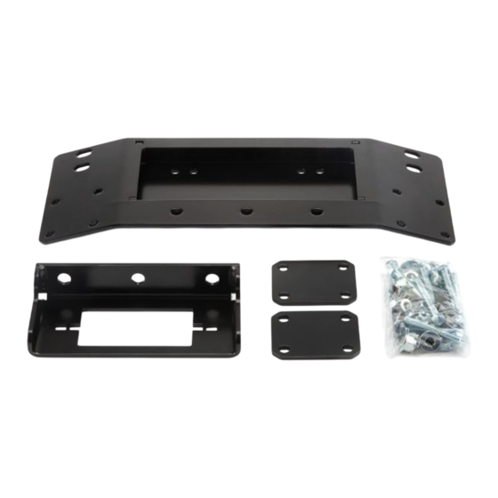
Page 10: Liste Des Pièces
Vis d'assemblage à tête hexagonale M8 – 1,25 X 20 81813 Rondelle de blocage M8 83474 Boulon de carrosserie M10 x 1.5 x 25 79882 93923A1 ©2014 Warn Industries, Inc.WARN® and the WARN logo are trademarks of Warn Industries Inc. - Page 11 3) Alignez le kit de montage du treuil avec les boulons M8 insérés à l'étape 2. Fixez solidement le support de montage du treuil en utilisant les écrous à embase M8. Figure 3 93923A1 ©2014 Warn Industries, Inc.WARN® and the WARN logo are trademarks of Warn Industries Inc.
- Page 12 6) Fixez l'ensemble du guide-câble au son support de montage du treuil en utilisant deux boulons à embase M10 et des écrous de blocage. Figure 6 93923A1 ©2014 Warn Industries, Inc.WARN® and the WARN logo are trademarks of Warn Industries Inc.
- Page 13 à épaulement Figure 9 10) Terminez l’installation du treuil telle que décrite dans le guide d’installation et de spécification du treuil fourni avec treuil. Figure 10 93923A1 ©2014 Warn Industries, Inc.WARN® and the WARN logo are trademarks of Warn Industries Inc.
- Page 14 TOUTE INSTALLATION OU UTILISATION IMPRUDENTE PEUT ENTRAÎNER DES BLESSURES GRAVES OU ENDOMMAGER L'ÉQUIPEMENT. PRENDRE SOIN DE LIRE ET DE BIEN ASSIMILER LES CONSIGNES DE SÉCURITÉ ET D'UTILISATION DU PRODUIT AVANT DE L'INSTALLER ET DE L'UTILISER. 93923A1 ©2014 Warn Industries, Inc.WARN® and the WARN logo are trademarks of Warn Industries Inc.