Table des Matières
Publicité
Les langues disponibles
Les langues disponibles
Liens rapides
Fritz Kübler GmbH
Zähl- und Sensortechnik
Postfach 34 40
D-78023 Villingen-Schwenningen
Tel.: 07720-3903-0
Fax: 07720-21564
www.kuebler.com
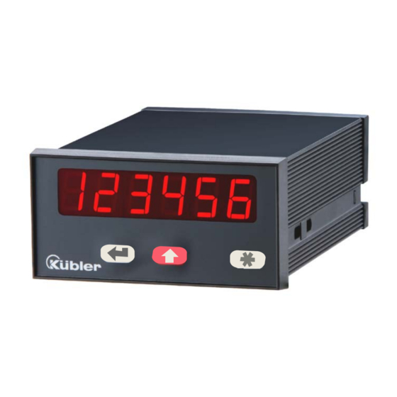
Prozesssteuergeräte 573
2 Analogeingängen und Berechnung
6.573.011.E00:
Prozesssteuergerät mit 2 Grenzwerten und Optokoppler-Ausgängen
6.573.012.E90:
Prozesssteuergerät mit Analogausgängen 0 - 10 V und 0/4 – 20 mA
• Zwei unabhängig skalierbare Analog-Eingänge, jeweils +/- 10V oder 0/4 – 20 mA
• Betriebsarten zur Anzeige von Kanal A, Kanal B sowie den Verknüpfungen
A + B, A - B, A x B und A : B
• Frei skalierbare Anzeigewerte und Nullpunktsverschiebung
• Nützliche Zusatzfunktionen wie Tara-Funktion, einstellbare Mittelwertbildung,
programmierbare Linearisierung usw.
• Versorgung 115/230 VAC und 17-30 VDC in einem Gerät
• Hilfsspannungsausgang 24 VDC / 100 mA zur Versorgung von Sensoren
Bedienungsanleitung für Ausführung
6.573.011.E00 mit 2 Grenzwerten
6.573.011.E00_7b_d.doc / Sep-08
Multi-funktionale Geräte mit
Page 1 / 28
Publicité
Chapitres
Table des Matières

Manuels Connexes pour Kübler 573 Serie

Sommaire des Matières pour Kübler 573 Serie
- Page 1 Fritz Kübler GmbH Zähl- und Sensortechnik Postfach 34 40 D-78023 Villingen-Schwenningen Tel.: 07720-3903-0 Fax: 07720-21564 www.kuebler.com Prozesssteuergeräte 573 Multi-funktionale Geräte mit 2 Analogeingängen und Berechnung 6.573.011.E00: Prozesssteuergerät mit 2 Grenzwerten und Optokoppler-Ausgängen 6.573.012.E90: Prozesssteuergerät mit Analogausgängen 0 - 10 V und 0/4 – 20 mA •...
- Page 2 Sicherheitshinweise • Diese Beschreibung ist wesentlicher Bestandteil des Gerätes und enthält wichtige Hinweise bezüglich Installation, Funktion und Bedienung. Nichtbeachtung kann zur Beschädigung oder zur Beeinträchtigung der Sicherheit von Menschen und Anlagen führen! • Das Gerät darf nur von einer Elektrofachkraft eingebaut, angeschlossen und in Betrieb genommen werden •...
-
Page 3: Table Des Matières
Inhaltsverzeichnis 1. Allgemeine Angaben..................4 2. Elektrische Anschlüsse .................. 5 Stromversorgung ....................... 5 Hilfsspannungsausgang .................... 6 Analoge Messeingänge A und B ................6 Optokoppler-Transistor-Ausgänge ................6 3. Einstellung der Jumper .................. 7 4. Funktion der Programmiertasten..............9 Normalbetrieb......................9 Allgemeine Parametrierung..................10 4.2.1 Parameter-Auswahl ......................10 4.2.2... -
Page 4: Allgemeine Angaben
1. Allgemeine Angaben Immer wieder stellt sich an eine analoge Prozess-Anzeige die Anforderung an hohe Flexibilität bei gleichzeitig leichter Bedienbarkeit. Für viele Anwendungen sind zwei unabhängige Eingänge notwendig, die einzeln oder in Kombination verarbeitet und angezeigt werden können. Ebenso ist es auch immer wieder notwendig, nichtlineare Analogsignale hinreichend genau auszuwerten und darzustellen, was eine programmierbare Linearisierungs-Funktion erfordert. -
Page 5: Elektrische Anschlüsse
2. Elektrische Anschlüsse 1 2 3 4 5 6 7 8 9 10 optional, siehe *) *) Der gestrichelt eingezeichnete Erdungsanschluss ist intern mit Gerätemasse verbunden und ist sicherheitstechnisch oder EMV- technisch nicht notwendig. Bei manchen Anwendungen kann es jedoch wünschenswert sein, das Bezugspotential für die Signale geräteseitig zusätzlich zu erden. -
Page 6: Hilfsspannungsausgang
2.2 Hilfsspannungsausgang An Klemme 7 steht, unabhängig von der Art der Geräteversorgung, eine Hilfsspannung von 24 VDC/max. 150 mA zur Versorgung von Gebern und Sensoren zur Verfügung. 2.3 Analoge Messeingänge A und B Es sind 2 Analogeingänge mit gemeinsamem Minus-Potential verfügbar (Eingang A und B). Bezugspotential ist jeweils Klemme 5 (AGND), die intern mit den Klemmen 1, 6 und GND verbunden ist. -
Page 7: Einstellung Der Jumper
3. Einstellung der Jumper Wenn das Messsignal ein Stromsignal 0-20 mA oder 4-20 mA ist, müssen keine Jumper verändert werden und Sie können diesen Abschnitt überspringen. Wenn jedoch ein Eingang oder beide Eingänge zur Messung von Spannungen benutzt werden sollen, müssen die internen Jumper entsprechend umgesteckt werden. Bei falsch konfigurierten Eingängen kann das Gerät beschädigt werden! Zum Verändern der Jumper müssen die Schraubklemmleisten abgesteckt und die Rückwand des Gerätes abgenommen werden. - Page 8 Eingang A = Strom, Eingang A = Spannung Eingang B = Spannung Eingang B = Spannung Nach Einstellung der Jumper Platine bitte vorsichtig in das Gehäuse zurückschieben, damit die Übergabestifte zur frontseitigen Tastatur nicht beschädigt werden. Strom-Eingänge sind automatisch auf einen Eingangsbereich von 0/4 – 20 mA abgestimmt.
-
Page 9: Funktion Der Programmiertasten
4. Funktion der Programmiertasten Das Gerät wird über 3 frontseitige Tasten bedient, die im weiteren Verlauf dieser Beschreibung wie folgt benannt werden: ENTER (Eingabe) (Einstellung) (Command) Die Tastenfunktion hängt von dem jeweiligen Betriebszustand des Gerätes ab. Es werden drei Betriebszustände unterschieden. •... -
Page 10: Allgemeine Parametrierung
4.2 Allgemeine Parametrierung 4.2.1 Parameter-Auswahl Die linke Taste (ENTER) rollt die einzelnen Menüpunkte durch. Mit der mittleren Taste (SET) wird ein entsprechender Menüpunkt angewählt, und die gewünschte Auswahl getroffen bzw. der zugehörige Zahlenwert verändert. Wiederum mit der ENTER- Taste wird die Auswahl oder der Wert bestätigt und zum nächsten Menüpunkt weitergeschaltet. -
Page 11: Teach-Funktion
4.3 Teach-Funktion Beim Teachen ist die Time-Out-Funktion abgeschaltet. Taste Verwendung Die ENTER-Taste dient zum Beenden oder zu Abbruch des Teach-Vorgangs Funktion wie bei normaler Parametrierung Die Cmd-Taste dient zur Übernahme des angezeigten Displaywertes und zum automatischen weiterschalten auf den nächsten Eingabewert. Die Beschreibung des Teach-Vorgangs erfolgt in Abschnitt 8.3. -
Page 12: Das Bedien-Menü
5. Das Bedien-Menü Das Bedienmenü besteht aus einem Grundmenü und einem Menü für die Betriebsparameter. Es erscheinen nur diejenigen Betriebsparameter, die im Grundmenü auch freigegeben wurden. Wenn z.B. im Grundmenü die Linearisierungsfunktion ausgeschaltet wurde, dann werden im Parametermenü die Linearisierungsparameter auch nicht angezeigt. Die Parameter selbst werden auf der Anzeige so gut wie möglich als Texte dargestellt. -
Page 13: Die Parameter
6. Die Parameter 6.1 Grundeinstellungen Die nachfolgend beschriebenen Einstellungen sind in der Regel nur bei der erstmaligen Inbetriebnahme notwendig. Es wird zunächst die Parametrierung der reinen Anzeige beschrieben. Zusätzliche Einstellungen für die Grenzwerte werden aus Gründer besserer Übersicht später separat erklärt. Menüpunkt Default Betriebsart des Gerätes... -
Page 14: Betriebsparameter
Menüpunkt Default Tastaturbefehle Command-Taste Cmd Tastenfunktion ist ausgeschaltet. Offset-Werte werden nicht angezeigt Der Cmd-Taste ist die Tara- bzw. Offset-Funktion zugeordnet Der Cmd-Taste ist die Teach-Funktion zugeordnet Der Cmd-Taste sind sowohl Tara-Funktion als auch Teach-Funktion zugeordnet. 6.2 Betriebsparameter Wenn die vorgenannten Grundeinstellungen getroffen sind, kann durch Betätigung der Taste „ENTER“... -
Page 15: Betriebsarten
6.4 Betriebsarten 6.4.1 Single Mode (Nur Kanal A) Menüpunkt Einstellbereich Default Eingangsbereich Eingang A Stellen Sie hier die gewünschte Konfiguration des Eingang A ein. Spannung +/-10V Strom 0-20 mA Strom 4-20 mA Startwert Eingang A -99999 … 99999 Geben Sie hier den gewünschten Anzeigewert für ein Eingangssignal von 0V, 0mA bzw. -
Page 16: Dual Mode (Kanal A Und B)
6.4.2 Dual Mode (Kanal A und B) In dieser Betriebsart kann die Anzeige mit der mittleren Taste (SET) zwischen Kanal A und Kanal B hin- und hergeschaltet werden. Ein Balken auf der vordersten Dekade zeigt an, ob Sie gerade Kanal A oder Kanal B ablesen (siehe Abb. -
Page 17: Verknüpfte Modes (A+B, A-B, A:b, A•B)
6.4.3 Verknüpfte Modes (A+B, A-B, A:B, A•B) Bei dieser Betriebsart können sowohl die Einzelkanäle A und B als auch das Resultat der Verknüpfung angezeigt werden. Mit Hilfe der mittleren Taste (SET) kann zwischen den Einzelwerten und der Verknüpfung umgeschaltet werden. Ist Eingang A auf dem Display aktiv, wird auf der höchsten Stelle der obere Querstich eingeblendet. -
Page 18: Parameter Für Die Grenzwertvorgaben
6.4.4 Parameter für die Grenzwertvorgaben Grundeinstellungen für die Grenzwerte: Bereits im Grundeinstell-Menü erscheinen zusätzlich die folgenden Parameter: Menüpunkt Einstellbereich Default Schaltcharakteristik Ausgang 1 Greater/Equal: Ausgang wird statisch aktiv, wenn Anzeigewert größer oder gleich Vorwahlwert ist. Lower/Equal: Ausgang wird statisch aktiv, wenn Anzeigewert kleiner oder gleich Vorwahlwert ist. - Page 19 Messwert Die Arbeitsrichtung der Hysterese Schalthysterese hängt Vorwahlwert von der Vorgabe der Hysterese Schaltcharakteristik „GE“ bzw. „LE“ ab und ist im nebenstehenden GE=Greater/Equal Bild erklärt. LE=Lower/Equal Soweit Wischimpulse programmiert werden, beträgt die Impulszeit des Ausganges jeweils 300 msec (Festwert, nur werksseitig veränderbar). Betriebseinstellungen für die Grenzwerte: Die Vorwahlwerte selbst werden direkt am Anfang des normalen Bedienmenüs abgefragt bzw.
- Page 20 • Bei Betrieb im“ Single Mode“ oder einem „Verknüpften Mode“ richten sich beide Vorwahlen stets nach dem zur Anzeige gebrachten Messwert. Bitte beachten Sie, dass sich ein hin- und herschalten der Anzeige daher auch auf die Ausgänge auswirkt. • Im „Dual Mode“ ist automatisch Vorwahl 1 dem Eingangskanal A und Vorwahl 2 dem Eingangskanal B zugeordnet, unabhängig davon, welcher Wert gerade angezeigt wird.
-
Page 21: Inbetriebnahme
7. Inbetriebnahme Die Inbetriebnahme des Gerätes ist denkbar einfach, wenn Sie der Reihe nach die folgenden Schritte durchführen: Gegenstand Einstellungsschritt Siehe Abschnitt Analog-Eingänge • Jumper setzen Abschnitt 3 Grundeinstellungen • Betriebsart wählen Abschnitt 6.1 • Linearisierung und Tara-Funktion zunächst Abschnitt 6.1 ausgeschaltet lassen Parametermenü... -
Page 22: Sonderfunktionen
8. Sonderfunktionen 8.1 Tara/Offset-Funktion Die Tara-Funktion wird aktiviert, indem der Parameter „Cmd“ auf „oFFSEt“ oder „both“ gesetzt wird. Bei eingeschalteter Tara-Funktion wird mit jeder Betätigung der „Cmd“-Taste der momentane Anzeigewert in das Offset-Register übernommen, womit die Anzeige auf Null gesetzt wird. 8.2 Linearisierung Mit Hilfe dieser Funktion kann auf einfache Weise ein lineares Eingangssignal in eine nichtlineare Darstellung umgewandelt werden. - Page 23 P1(x)= -1000 P1(y)= 900 P8(x)= 0 P16(x)= 1000 P8(y)= 750 P16(y)= 800 P16(x)= +1000 P1(x)= 0 P16(y)= - 600 P1(y)= 0 Linearisation Mode = 4_quA Linearisation Mode = 1_quA Anwendungsbeispiel: Mit Hilfe eines Drucksensors soll die Füllmenge (Volumen) eines Behälters ermittelt und angezeigt werden.
-
Page 24: Manuelle Eingabe Oder „Teachen" Der Linearisierungspunkte
8.3 Manuelle Eingabe oder „Teachen“ der Linearisierungspunkte Die Punkte zur Bildung einer Linearisierungskurve können wie alle Parameter mit dem normalen Tastatur-Dialog vorgegeben werden. In diesem Falle werden alle Werte P01_x bis P16_x und die zugeordneten Ersatzwerte P01_y bis P16_y einzeln eingegeben. Der Benutzer muss bei manueller Eingabe die Konsistenz der Werte P01_x bis P16_x gewährleisten, d.h. -
Page 25: Variable Updatezeit Der Anzeige Und Reaktionszeit
• Betätigen Sie nochmals „Cmd“, um den momentan anliegenden Istwert anzuzeigen. Sorgen Sie nun dafür, dass das Eingangssignal dem ersten, gewünschten Lineari- sierungs-Stützpunkt entspricht (bei verknüpftem Betrieb beide Eingangssignale). • Sobald Sie in der Anzeige den X-Wert des ersten Linearisierungspunktes sehen, drücken Sie erneut die „Cmd“-Taste. -
Page 26: Technischer Anhang
9. Technischer Anhang 9.1 Maßbilder 110,0 96,0 91,0 1 2 3 4 5 6 7 8 21,0 129,0 140,5 Schalttafel-Ausschnitt: 91 x 44 mm 6.573.011.E00_7b_d.doc / Sep-08 Page 26 / 28... -
Page 27: Technische Daten
9.2 Technische Daten Nennspannung AC : 115/230 V (+/- 12,5 %), 7,5 VA Nennspannung DC : 24V (17 – 30V), ca. 100 mA (ohne Sensorstrom) Anschlussleistung : 7,5 VA Stromaufnahme bei DC-Versorgung 18V : 110mA, 24V : 90 mA, 30V : 80mA (ohne Geber) Hilfsspannung für Sensor : 24V DC, +/- 15%, 100mA (bei AC und bei DC) -
Page 28: Inbetriebnahmeformular
9.3 Inbetriebnahmeformular Datum: Operator: Software: Seriennummer: Analogeingänge Eingang A Eingang B Eingangsbereich: Spannung +/- 10 V Spannung +/- 10 V Strom 0 – 20 mA Strom 0 – 20 mA Strom 4 – 20 mA Strom 4 – 20 mA Startwert:: Endwert:: Dezimalpunkt:... - Page 29 Fritz Kübler GmbH Zähl- und Sensortechnik Postfach 34 40 D-78023 Villingen-Schwenningen Tel.: 07720-3903-0 Fax: 07720-21564 www.kuebler.com Process Controller Series 573 Multi-Function Units with Two Analogue Inputs and Calculations 6.573.011.E00: Process Controller with 2 Presets and Optocoupler Outputs 6.573.012.E90: Process Controller with Analogue Outputs 0 - 10 V und 0/4 – 20 mA •...
- Page 30 Safety Instructions • This manual is an essential part of the unit and contains important hints about function, correct handling and commissioning. Non-observance can result in damage to the unit or the machine or even in injury to persons using the equipment! •...
- Page 31 Table of Contents 1. Introduction....................4 2. Terminal Assignments ................... 5 2.1. Power supply ......................5 2.2. Aux. voltage output ....................6 2.3. Analogue inputs ....................6 2.4. Optocoupler (transistor) outputs ................6 3. Jumper settings ..................... 7 4. How to Operate the Keys................9 4.1.
-
Page 32: Introduction
1. Introduction Some of the general demands to an up-to-date process controller for automation industry are always high flexibility, combined with easy and simple operability. Many applications require two separate analogue inputs for use with single or combined operation. Also it may be important to display and evaluate both, linear and non-linear analogue inputs at an acceptable accuracy, which requires programmable linearisation functions. -
Page 33: Terminal Assignments
2. Terminal Assignments 1 2 3 4 5 6 7 8 9 10 optional, see *) The connection of PE is optional and not necessary for safety or for EMC. However, with some applications, it can be useful to ground the common potential of all signal lines •... -
Page 34: Aux. Voltage Output
2.2. Aux. voltage output Terminal 7 provides an auxiliary output of 24 VDC / 150 mA max. for supply of sensors and encoders. This is valid for AC supply and DC supply of the unit as well. 2.3. Analogue inputs There are two analogue inputs with common minus potential available (Input A and Input B). -
Page 35: Jumper Settings
3. Jumper settings When your input signal is a current of 0-20 mA or 4-20 mA, there is no need to change jumper settings and you can skip this section. Where, however, you intend to use one or both inputs for voltage signals, you must change the internal jumper settings correspondingly. - Page 36 Input A = current, input B = voltage Input A = voltage, input B = voltage After setting the jumpers, please shift the print carefully back to the housing, in order not to damage the front pins for connection to the keypad plate. Current inputs are automatically scaled to an input range of 0/4 –...
-
Page 37: How To Operate The Keys
4. How to Operate the Keys The unit uses 3 front keys for all setup operations. Subsequently, the key functions will be named as shown in the table below. ENTER (Command) The functions of the keys are depending on the actual operating state of the unit. The following three operating states apply: •... -
Page 38: Parameter Settings
4.2. Parameter settings 4.2.1. How to select a parameter The ENTER key will scroll through the menu. The SET key allows to select the corresponding item and to change the setting or the numeric value. After this, the selection can be stored by ENTER again, which automatically changes over to the next menu item. -
Page 39: Teach Operation
4.3. Teach operation The Time-out function will be switched off during all Teach operations Function ENTER will conclude or abort any Teach operation in progress SET function is fully similar to normal set-up operation Cmd will store the display value to the register and will change over to the next interpolation point. -
Page 40: The Parameter Menu
5. The Parameter Menu The menu provides one section with “basic parameters” and another section with “operational parameters”. On the display you will only find those parameters which have been enabled by the basic settings. E.g. when the Linearisation Functions have been disabled in the basic set- up, the associated linearisation parameters will also not appear in the parameter menu. -
Page 41: Setup Procedure
6. Setup Procedure 6.1. Basic Parameters In general, the parameters described subsequently must be set with the very first commissioning of the unit only. For best comprehensibility, this section describes setup of all display functions only, and settings applicable to preselections and switching outputs are described separately. -
Page 42: Operational Parameters
Menu Text Default Command key enable The Command key is switched off and no Offset values will appear in the menu The Cmd key will execute the Tare/Offset function The Cmd key will execute the Teach function The Cmd key will execute both, the Tare and the Teach function 6.2. -
Page 43: Modes Of Operation
6.4. Modes of operation 6.4.1. Single mode (input A only) Menu Text Setting Range Default Input A range Set the desired range for input A Voltage +/-10V Current 0-20 mA Current 4-20 mA Start value -99999 … 99999 Value which the unit will display with a zero input signal of 0 volts or 0/4 mA End value -99999 …... -
Page 44: Dual Mode (Inputs A And B Separately)
6.4.2. Dual Mode (Inputs A and B separately) With this mode, the SET key selects between display of channel A and display of channel B, and the bar of the high order LED indicates which of the two channels is actually in display. Menu Text Input Range Default... -
Page 45: Combined Modes (A+B, A-B, A:b, A•B)
6.4.3. Combined Modes (A+B, A-B, A:B, A•B) These modes allow displaying either the single channels A and B or the calculated result according to the selected combination. The SET key allows scrolling between the three displays. The upper bar of the high order digit indicates that you display channel A. -
Page 46: Additional Settings For Use Of The Preselections
6.4.4. Additional settings for use of the Preselections Basic settings for Presets: The basic setup menu provides the following additional parameters which are relevant for the operation of the presets and outputs only: Menu Text Setting Range Default Output 1 switching characteristics Greater/Equal: Output is statically active with display greater or equal Preset. - Page 47 Display value The direction of Hysteresis operation of the Preset value Hysteresis setting Hysteresis depends on the selected switching characteristics „GE“ or. „LE“. GE=Greater/Equal LE=Lower/Equal See adjoining figure Where the switching outputs have been set to dynamic operation, the output impulse time is always 300 msec.
- Page 48 • With all applications using “Single Mode” (6.4.1) or one of the “Combined Modes” (6.4.3), both presets always refer to the actual value appearing in display. Please be aware that toggling the display will affect the outputs • Use of “Dual Mode” (6.4.2) automatically attaches Preset 1 to input channel A and Preset 2 to input channel B, independent on which of the values is actually in display •...
-
Page 49: Commissioning
7. Commissioning Commissioning of this unit is easy and uncomplicated when following the subsequent steps: Step Action See section Analogue inputs • Set jumpers Basic settings • Select Operation mode • Keep linearisation and Tare function off firstly Parameter settings •... -
Page 50: Special Functions
8. Special Functions 8.1. Tare / Offset function This function will become active after the “Cmd” parameter has been set to “oFFSEt” or to “both”(see 6.1). As a result, every touch of the “Cmd” key will store the actual display value to the Offset register, resulting in a Zero display with the actual input signal. - Page 51 P1(x)= -1000 P1(y)= 900 P8(x)= 0 P16(x)= 1000 P8(y)= 750 P16(y)= 800 P16(x)= +1000 P1(x)= 0 P16(y)= - 600 P1(y)= 0 Linearisation Mode = 4_quA Linearisation Mode = 1_quA Application Example: We like to display the filling quantity (volume) of a tank as shown below, with use of a pressure sensor mounted to the bottom of the tank.
-
Page 52: Manual Input Or „Teaching" Of The Interpolation Points
8.3. Manual input or „Teaching“ of the interpolation points Interpolation points to form the linearisation curve can be entered one after another, using the same procedure as for all other numeric parameters. This means you will enter all parameters P01_x to P16_x and P01_y to P16_y manually by keypad. During manual input of interpolation points the unit will not examine the settings P01_x to P16_x. -
Page 53: Update Time Of The Display And Response Time Of Outputs
• Press once more “Cmd” to display the actual analogue input signal. Now arrange for the desired analogue input signal of the first interpolation point (with combined modes please arrange for both analogue signals) • When you read the x-value of your first interpolation point in the display, press “Cmd” again. -
Page 54: Technical Specifications
9. Technical Specifications 9.1. Dimensions 110,0 (4.331’’) 91,0 (3.583) 96,0 (3.780’’) 9,0 (.345) 129,0 (5.079) 140,5 (5.531) Panel cut out: 91 x 44 mm (3.583 x 1.732’’) 6.573.011.E00_7b_e.doc / Sep-08 Page 26 / 28... -
Page 55: Technical Data
9.2. Technical data Power supply AC : 115/230 V (+/- 12,5 %), 7,5 VA Power supply DC : 24 V (17 – 30 V), approx. 100 mA (without aux. sensor supply) Total AC power : 7,5 VA DC current consumption 18 V : 110 mA, 24 V : 90 mA, 30 V : 80 mA (without sensors) Aux. -
Page 56: Commissioning Form
9.3. Commissioning Form Date: Operator: Software: Serial No.: Analogue Inputs Input A Input B Input range: Voltage +/- 10 V Voltage +/- 10 V Current 0 – 20 mA Current 0 – 20 mA Current 4 – 20 mA Current 4 – 20 mA Start value: End value: Decimal point:... - Page 57 Fritz Kübler GmbH Zähl- und Sensortechnik Postfach 34 40 D-78023 Villingen-Schwenningen Tel.: 07720-3903-0 Fax: 07720-21564 www.kuebler.com Afficheur de process 573 Appareil multifonction avec 2 entrées analogiques et calcul 6.573.011.E00 : Afficheur de process avec 2 valeurs limites et sorties optocoupleurs 6.573.012.E90 : Afficheur de process avec sorties analogiques 0 - 10 V et 0/4 –...
- Page 58 Consignes de sécurité • La présente notice est un élément essentiel de l’appareil et contient des consignes importantes concernant l’installation, les fonctions et l’utilisation. Le non-respect peut occasionner des dommages ou porter atteinte à la sécurité des personnes et des installations. •...
- Page 59 Table des matières 1. Introduction..................... 4 2. Raccordements électriques................5 2.1. Alimentation......................5 2.2. Sortie de tension auxiliaire ..................6 2.3. Entrées de mesures analogiques A et B ..............6 2.4. Sorties transistor optocouplées ................6 3. Préréglage des entrées analogiques .............. 7 4. Fonction des touches de programmation............9 4.1.
-
Page 60: Introduction
1. Introduction Un afficheur de process analogique doit constamment répondre à des critères de flexibilité et de facilité d’utilisation. De nombreuses applications exigent deux entrées indépendantes, pouvant être utilisées et affichées individuellement ou ensemble. Il peut également arriver que l’on doive évaluer et représenter avec précision des signaux analogiques non linéaires, ce qui nécessite une fonction de linéarisation programmable. -
Page 61: Raccordements Électriques
2. Raccordements électriques 1 2 3 4 5 6 7 8 9 10 *) La prise de terre indiquée en pointillés est reliée en interne à la masse de l’appareil et n’est pas indispensable sur le plan de la sécurité ou de la compatibilité électromagnétique. Pour certaines utilisations, il est toutefois recommandé... -
Page 62: Sortie De Tension Auxiliaire
2.2. Sortie de tension auxiliaire La borne 7 dispose d’une tension auxiliaire de 24 VDC/max. 100 mA pour alimenter les codeurs et capteurs, et ce quel que soit le type d’alimentation de l’appareil. 2.3. Entrées de mesures analogiques A et B Il existe 2 entrées analogiques avec potentiel négatif commun (Entrée A et Entrée B). -
Page 63: Préréglage Des Entrées Analogiques
3. Préréglage des entrées analogiques Lorsque le signal de mesure est un signal courant de 0-20 mA ou 4-20 mA, l’utilisation de cavaliers n’est pas nécessaire et vous pouvez sauter ce paragraphe. Mais dès lors qu’une entrée ou les deux entrées sont utilisées pour mesurer des tensions, les cavaliers internes doivent être permutés en conséquence. - Page 64 Entrée A = tension, Entrée B = tension Entrée A = courant, Entrée B = tension Après mise en place des cavaliers, veuillez insérer la platine soigneusement dans le boîtier afin de ne pas endommager les broches frontales vers le clavier ! Les entrées courant sont automatiquement réglées sur une plage d’entrée de 0/4 –...
-
Page 65: Fonction Des Touches De Programmation
4. Fonction des touches de programmation L’utilisation de l’appareil se fait au moyen de 3 touches frontales. ENTER (Confirmation) (Sélection) (Commande) La fonction des touches dépend de l’état de fonctionnement de l’appareil. On distingue trois états de fonctionnement. • Affichage normal •... -
Page 66: Réglages Et Paramètres
4.2. Réglages et paramètres 4.2.1. Sélection des paramètres La touche gauche (ENTER) sert à dérouler les différents points du menu. La touche moyenne (SET) permet de sélectionner un point du menu et de choisir le réglage souhaité ou de régler la valeur numérique désirée. Appuyez une nouvelle fois sur la touche ENTER pour confirmer le choix ou la valeur et pour passer au point de menu suivant. -
Page 67: Fonction Teach
4.3. Fonction Teach Pendant l’utilisation de la fonction Teach, la fonction Time-out est désactivée. Touche Utilisation La touche ENTER permet de terminer ou d’interrompre le procédé Teach Même fonction que pour un paramétrage normal La touche Cmd sert à prendre en compte la valeur affichée et à passer automatiquement à... -
Page 68: Le Menu Des Réglages
5. Le menu des réglages Le menu d’utilisation comprend un menu de base et un menu pour les paramètres de fonctionnement. Seuls apparaissent les paramètres de fonctionnement qui ont également été validés dans le menu de base. Exemple : si la linéarisation est désactivée dans le menu de base, les paramètres de linéarisation ne seront pas non plus affichés dans le menu des paramètres. -
Page 69: Réglages Et Paramètres
6. Réglages et paramètres 6.1. Réglages de base Les réglages décrits ci-dessous s’effectuent normalement en une seule fois, lors de la première mise en service de l’appareil. Le menu de base comprend le choix du mode de fonctionnement avec les paramètres correspondants ainsi que la luminosité souhaitée de l’affichage numérique. -
Page 70: Paramètres De Fonctionnement
Point de menu Plage Défaut Commandes clavier de la touche de commande Cmd La fonction de la touche est désactivée. Les valeurs offset ne sont pas affichées. La fonction tare ou offset est affectée à la touche Cmd. La fonction Teach est affectée à la touche Cmd. La fonction tare et la fonction Teach sont affectées à... -
Page 71: Modes De Fonctionnement
6.4. Modes de fonctionnement 6.4.1. Mode monocanal (Single) Point de menu Plage Défaut Plage d’entrée Entrée A Entrée tension 0 - +/-10 V Entrée courant 0 – 20 mA Entrée courant 4 – 20 mA Valeur initiale (canal A) devant être affichée -99999 …... - Page 72 6.4.2. Mode bicanal (Dual) Dans ce mode de fonctionnement, la touche SET permet d’alterner entre le canal A et le canal B. Les deux canaux sont paramétrables séparément. La présence d’une barre sur la première décade indique si vous êtes en train de lire le canal A ou le canal B.
- Page 73 6.4.3. Paramètres de fonctionnement pour modes combinés ( A+B, A-B, AxB, A:B ) Ce mode de fonctionnement permet d’afficher aussi bien les canaux A et B séparément que le résultat de la combinaison. Pour choisir entre les valeurs individuelles ou la combinaison, actionnez la touche moyenne (Set).
- Page 74 6.4.4. Paramètres pour les présélections Les paramètres suivants apparaissent dans le menu réglages de base. Point du menu Plage Défaut Caractéristique de commutation sortie 1 Greater/Equal. La sortie est statiquement active lorsque la valeur d’affichage est supérieure ou égale à la valeur de présélection.
- Page 75 Le sens de travail de Valeur effective Hystérésis l’hystérésis de Seuil commutation dépend de la configuration de la Hystérésis caractéristique de commutation “GE“ ou GE=Greater/Equal “LE“, selon l’explication d’à coté LE=Lower/Equal En cas de programmation de signaux de passage, la durée de l’impulsion de sortie est fixée à 300 msec.
- Page 76 • En cas de fonctionnement en mode « Single » ou en mode « Combiné », les deux présélections s’orientent toujours d’après la valeur mesurée affichée. Veuillez noter que toute manipulation de l’affichage se répercute également sur les sorties. • En « mode Dual », la présélection 1 est automatiquement affectée au canal d’entrée A et la présélection 2 au canal d’entrée B, quelle que soit la valeur affichée.
-
Page 77: Mise En Service
7. Mise en service La mise en service de l’appareil est très facile à effectuer, à condition de suivre les étapes ci- dessous dans l’ordre indiqué : Objet Réglage Voir paragraphe Entrées analogiques • Pose des cavaliers Réglages de base •... -
Page 78: Fonctions Spéciales
8. Fonctions spéciales 8.1. Fonction tare / offset Pour activer la fonction tare, positionnez Cmd sur « oFFSEt » ou « both » dans les paramètres de base. Lorsque la fonction tare est activée, il suffit d’actionner la touche Cmd pour intégrer la valeur d’affichage actuelle dans le registre offset. - Page 79 Le plan ci-dessous explique la différence de principe entre les modes de linéarisation « 1_quA » et « 4_quA ». P1(x)= -1000 P1(y)= P8(x)= 0 P8(y)= 750 P16(x)= 1000 P16(y)= 800 P1(x)= 0 P16(x)= +1000 P1(y)= 0 P16(y)= - 600 Mode de linéarisation = 1_quA Mode de linéarisation = 4_quA Exemple d’application :...
-
Page 80: Saisie Manuelle Ou Mode Teach Des Points De Linéarisation
8.3. Saisie manuelle ou mode Teach des points de linéarisation Les points permettant d’obtenir une courbe de linéarisation peuvent être préréglés à l’aide du dialogue clavier normal, comme tous les autres paramètres. Dans ce cas, toutes les valeurs P01_x à P16_x et les valeurs de remplacement correspondantes P01_y à P16_y seront saisies individuellement. -
Page 81: Temps D'actualisation De L'affichage Et Des Sorties
• Actionnez une nouvelle fois la touche Cmd afin d’afficher la valeur réelle actuelle. Veillez à ce que le signal d’entrée corresponde au premier point de linéarisation souhaité (les deux signaux d’entrée en cas de fonctionnement combiné). • Dès que vous verrez apparaître sur l’afficheur la valeur X du premier point de linéarisation, appuyez une nouvelle fois sur la touche Cmd. -
Page 82: Annexe Technique
9. Annexe technique 9.1. Schémas 110,0 96,0 91,0 1 2 3 4 5 6 7 8 Côte de découpe pour encastrement sur pupitre ou tableau 91 x 44 mm 21,0 129,0 140,5 6.573.011.E00_7b_f.doc / Sep-08 Page 26 / 28... -
Page 83: Données Techniques
9.2. Données techniques Tension nominale AC 115/230 V (+/- 12,5 %), 7,5 VA Tension nominale DC 24V (17 – 30V), env. 100 mA (hors alimentation capteur) Tension auxiliaire pour capteur : 24V DC, +/- 15%, 100mA (pour AC et pour DC) Entrées 2 entrées analogiques (+/-10V, 0..20mA, 4..20mA) -
Page 84: Formulaire Récapitulatif
9.3. Formulaire récapitulatif Date: Operateur: Software: No. Série : Entrées analogiques Entrée A Entrée B Plage d’entrée: Tension +/- 10 V Tension +/- 10 V Courant 0 – 20 mA Courant 0 – 20 mA Courant 4 – 20 mA Courant 4 –...