Speck pumpen BADU Jet PRIMAVERA Installation

Speck pumpen BADU Jet PRIMAVERA Installation

Masquer les pouces Voir aussi pour BADU Jet PRIMAVERA:
Table des Matières

Publicité

Les langues disponibles
  • FR

Les langues disponibles

  • FRANÇAIS, page 87

Liens rapides

DE
Einbau-Gegenstrom-Schwimmanlage
BADU
EN
Submerged counter swim unit
BADU
FR
Installation de nage à contre-courant Encastrée
BADU
NL
Inbouwtegenstroominstallatie
BADU
IT
Gruppo di nuoto controcorrente da incasso
BADU
ES
Dispositivo contra corriente para mantaja en piscinas
BADU
12/2014
VG 766.2320.050 1' RE/BA
®
Jet primavera
®
Jet primavera
®
Jet primavera
®
Jet primavera
®
Jet primavera
®
Jet primavera
Hauptstraße 1-3
91233 Neunkirchen a. Sand
Germany
Tel. +49 9123-949-0
Fax +49 9123-949-260
info@speck-pumps.com
www.speck-pumps.com

Publicité

Table des Matières
loading

Sommaire des Matières pour Speck pumpen BADU Jet PRIMAVERA

  • Page 1 Einbau-Gegenstrom-Schwimmanlage ® BADU Jet primavera Submerged counter swim unit ® BADU Jet primavera Installation de nage à contre-courant Encastrée ® BADU Jet primavera Inbouwtegenstroominstallatie ® BADU Jet primavera Gruppo di nuoto controcorrente da incasso ® Jet primavera BADU Dispositivo contra corriente para mantaja en piscinas ®...
  • Page 2 Inhaltsverzeichnis Inhaltsverzeichnis DE Originalbetriebsanleitung für ........ 3 EN Original operation manual for ......45 FR Instruction d'utilisation originale pour ....86 NL Oorspronkelijke gebruikershandleiding voor .. 131 Manuale d'istruzioni originale per ..... 173 ES Instrucciones para el manejo originales para .. 217 2 DE│EN│FR│NL│IT│ES VG 766.2320.050 12/2014...
  • Page 3 Originalbetriebsanleitung für Einbau-Gegenstrom-Schwimmanlage Hauptstraße 1-3 91233 Neunkirchen a. Sand Germany Tel. +49 9123-949-0 Fax +49 9123-949-260 info@speck-pumps.com www.speck-pumps.com 12/2014 VG 766.2320.050 1’ RE/BA...
  • Page 4: Table Des Matières

    Inhaltsverzeichnis Inhaltsverzeichnis 1 Zu diesem Dokument ..............7 Umgang mit dieser Anleitung ........... 7 Mitgeltende Dokumente ............7 1.2.1 Symbole und Darstellungsmittel ........7 2 Sicherheit ..................9 Bestimmungsgemäße Verwendung ......... 9 2.1.1 Mögliche Fehlanwendungen .........9 Personalqualifikation ..............9 Sicherheitsvorschriften ............10 Schutzeinrichtungen ..............
  • Page 5 Inhaltsverzeichnis 5.1.3 Be- und Entlüftung ............17 5.1.4 Körper- und Luftschallübertragung ......17 5.1.5 Platzreserve ...............17 5.1.6 Befestigungselemente ..........17 Aufstellung ................18 5.2.1 Montage des Einbaugehäuses in ein Betonbecken ..20 5.2.2 Montage des Einbaugehäuses in Polyester-, Stahl- oder Alubecken ............22 5.2.3 Ausrichtung des Spannrings ........24 5.2.4 Schutzschlauch und Schlauch für Luftregulierung ..24 5.2.5 Rohrleitung dimensionieren ........25 5.2.6 Rohrleitung verlegen ..........25...
  • Page 6 Inhaltsverzeichnis Alle Rechte vorbehalten. Inhalte dürfen ohne schriftliche Zustimmung von Speck Pumpen Verkaufsgesellschaft GmbH weder verbreitet, vervielfältigt, bearbeitet noch an Dritte weitergegeben werden. Dieses Dokument sowie alle Dokumente im Anhang unterliegen keinem Änderungsdienst! Technische Änderungen vorbehalten! 6 DE VG 766.2320.050...
  • Page 7: Zu Diesem Dokument

    1 Zu diesem Dokument Zu diesem Dokument Umgang mit dieser Anleitung Diese Anleitung ist Teil der Gegenstrom-Schwimmanlage. Die Anlage wurde nach den anerkannten Regeln der Technik hergestellt und geprüft. Dennoch können bei unsachgemäßer Verwendung, bei unzureichender Wartung oder unzulässigen Eingriffen Gefahren für Leib und Leben bzw.
  • Page 8 1 Zu diesem Dokument Um die korrekte Bedienung zu verdeutlichen, sind wichtige Informationen und technische Hinweise besonders herausgestellt. Symbol Bedeutung Einschrittige Handlungsaufforderung  Mehrschrittige Handlungsanleitung Reihenfolge der Schritte beachten.  8 DE VG 766.2320.050 12/2014...
  • Page 9: Sicherheit

    2 Sicherheit Sicherheit Bestimmungsgemäße Verwendung Zum Einbau in alle Schwimmbecken-Ausführungen als Attraktion, zur Fitness, als Wellen- oder Luftperlbad, zur Unterwassermassage nach ärztlichen Rat, zum Schwimmen ohne Wende. Zur bestimmungsgemäßen Verwendung gehört die Beachtung folgender Informationen: Diese Anleitung  Die Einbau-Gegenstrom-Schwimmanlage darf nur innerhalb der Einsatzgrenzen betrieben werden.
  • Page 10: Sicherheitsvorschriften

    2 Sicherheit Sicherstellen, dass folgende Voraussetzungen erfüllt sind:  – Das Personal, das die entsprechende Qualifikation noch nicht aufweisen kann, erhält die erforderliche Schulung, bevor es mit anlagentypischen Aufgaben betraut wird. – Die Zuständigkeiten des Personals, z. B. für Arbeiten am Produkt, an der elektrischen Ausrüstung oder den hydraulischen Einrichtungen, sind entsprechend seiner Qualifikation und Arbeitsplatzbeschreibung festgelegt.
  • Page 11: Schilder

    2 Sicherheit Schilder Alle Schilder auf der Anlage und dem Pumpenaggregat in lesbarem  Zustand halten. Restrisiken 2.7.1 Herabfallende Teile Nur geeignete und technisch einwandfreie Hebezeuge und  Lastaufnahmemittel verwenden. Nicht unter schwebenden Lasten aufhalten.  2.7.2 Rotierende Teile Scher- und Quetschgefahr besteht aufgrund von offenliegenden rotierenden Teilen.
  • Page 12: Heiße Oberflächen

    2 Sicherheit 2.7.4 Heiße Oberflächen Der Elektromotor kann eine Temperatur von bis zu 70 °C erreichen. Dadurch besteht Verbrennungsgefahr. Motor im Betrieb nicht berühren.  Vor Arbeiten an der Pumpe Motor erst abkühlen lassen.  2.7.5 Ansauggefahr WARNUNG! Folgende Gefährdungen können sich ergeben: –...
  • Page 13: Vermeidung Von Sachschäden

    2 Sicherheit Vermeidung von Sachschäden 2.9.1 Undichtigkeit und Rohrleitungsbruch Nichteinhaltung der Aushärtezeit der ABS-Verklebungen kann zu Undichtigkeit und Überschwemmungen führen. Aushärtezeit der ABS-Verklebungen von mindestens 12 Stdn.  einhalten. Ausreichenden Bodenablauf vorsehen.  Schwingungen und Wärmeausdehnung können Rohrleitungsbrüche verursachen. Anlage so installieren, dass Körper- und Luftschallübertragung ...
  • Page 14: Überhitzen

    2 Sicherheit 2.9.4 Überhitzen Folgende Faktoren können zu einer Überhitzung der Pumpe führen:  Zu hoher Druck auf der Druckseite  Falsch eingestellter Motorschutzschalter  Zu hohe Umgebungstemperatur Pumpe nicht bei geschlossenen Armaturen betreiben.  Motorschutzschalter installieren und korrekt einstellen. ...
  • Page 15: Beschreibung

    3 Beschreibung Beschreibung Komponenten (21/1) (54) (92) (111) (38/1) Einbaugehäuse (21/1) Mengenregulierung (92) Pumpe (38/1) Pneumatiktaster Pumpe (54) Düsen (38/2) Pneumatiktaster Licht (111) Luftregulierung Funktion Die Pumpe (92) ist über die Saug- und Druckleitung mit dem Kunststoff- Einbaugehäuse (1) verbunden. Mit dem Pneumatiktaster (38/1) wird die Pumpe EIN/AUS geschaltet.
  • Page 16: Transport Und Zwischenlagerung

    4 Transport und Zwischenlagerung Transport und Zwischenlagerung Korrosion durch Lagerung in feuchter Luft bei wechselnden Temperaturen! Kondenswasser kann Wicklungen und Metallteile angreifen. Pumpe in trockener Umgebung bei möglichst konstanter  Temperatur zwischenlagern. Beschädigung oder Verlust von Einzelteilen! Originalverpackung erst vor dem Einbau öffnen bzw. Einzelteile bis ...
  • Page 17: Installation

    5 Installation Installation Einbauort 5.1.1 Aufstellung im Freien Um die Lebensdauer der Pumpe zu erhöhen, einen einfachen  Regenschutz vorsehen. 5.1.2 Bodenablauf (muss vorhanden sein) Größe des Bodenablaufs nach folgenden Kriterien bemessen:  – Größe des Schwimmbeckens – Umwälzvolumenstrom 5.1.3 Be- und Entlüftung Für ausreichende Be- und Entlüftung sorgen.
  • Page 18: Aufstellung

    5 Installation Aufstellung ® Einbauhinweis BADU Jet primavera: Haltegriff Folie Spannring Edelstahlblende Beton Einbaugehäuse Dichtungen Ansaugblende Betonbecken mit Folie Haltegriff Spannringe Fliesen Edelstahlblende Beton Einbaugehäuse Dichtung Ansaugblende Betonbecken gefliest 18 DE VG 766.2320.050 12/2014...
  • Page 19 5 Installation Haltegriff Spannring Folie Edelstahlblende Beckenwand Einbaugehäuse Dichtungen Ansaugblende Folienbecken Haltegriff Spannring Edelstahlblende Beckenwand Einbaugehäuse Dichtungen Ansaugblende Polyesterbecken 12/2014 VG 766.2320.050 DE 19...
  • Page 20: Montage Des Einbaugehäuses In Ein Betonbecken

    5 Installation 5.2.1 Montage des Einbaugehäuses in ein Betonbecken Beachten Sie, dass der Druckanschluss oben über dem Sauganschluss angeordnet wird. Festlegung Einbautiefe: Mitte Einbaugehäuses / der Düsen soll sich 30 cm unter dem Wasserspiegel befinden. Die Noppendichtung (26) in das Gehäuse (1) einlegen, das Einbaugehäuse ausrichten und mit 4 Schneidschrauben an der Schalung befestigen.
  • Page 21 5 Installation Einbau an Schalung für Betonbecken Dicht-Rundschnur ! Druckanschluss OBEN ! Sauganschluss Schneidschraube Noppendichtung Schalung Schalung ~240 Abb.2 Montage des Einbaugehäuses in ein Betonbecken mit Folienauskleidung Bitte 5.2.3 beachten: Ausrichtung des Spannrings 34 106 Folie Abb. 3 12/2014 VG 766.2320.050 DE 21...
  • Page 22: Montage Des Einbaugehäuses In Polyester-, Stahl- Oder Alubecken

    5 Installation Montage des Einbaugehäuses in ein gefliestes Betonbecken Bitte 5.3.3 beachten: Ausrichtung des Spannrings 34 106 Abb.4 In einem gefliesten Becken wird die Fliesenstärke mit einem zusätzlichen Spannring (28) und längeren Schneidschrauben (52) ausgeglichen. Diese Teile sind im Zusatz-Kit optional erhältlich. 5.2.2 Montage des Einbaugehäuses in Polyester-, Stahl- oder Alubecken Beachten Sie, dass der Druckanschluss oben über dem Sauganschluss...
  • Page 23 5 Installation Einbauvorschlag für Polyesterbecken/Folienbecken Ø7 1) Befestigung Spannring (12x) Abb.5 Montage des Einbaugehäuses in ein Polyesterbecken Bitte 5.2.3 beachten: Ausrichtung des Spannrings 34 106 Polyesterbecken Abb.6 12/2014 VG 766.2320.050 DE 23...
  • Page 24: Ausrichtung Des Spannrings

    5 Installation Montage des Einbaugehäuses in ein Folienbecken Bitte 5.2.3 beachten: Ausrichtung des Spannrings 34 106 Folienbecken Abb. 7 5.2.3 Ausrichtung des Spannrings Die vier mit (1) markierten Bohrungen müssen immer im 45° Winkel zur Mittelachse stehen. Abb. 8 5.2.4 Schutzschlauch und Schlauch für Luftregulierung Schutzschlauch Schlauch...
  • Page 25: Rohrleitung Dimensionieren

    5 Installation 5.2.5 Rohrleitung dimensionieren Zu lange Saugleitungen haben erhebliche Nachteile:  Höherer Widerstand, dadurch schlechteres Ansaugverhalten und höhere Kavitionsgefahr  Längere Ansaugzeit (bis zu 12 Min). ACHTUNG! Das Einbaugehäuse und die Verschraubungen sind aus ABS. Eine Aushärtezeit der Verklebung von mindestens 12 Stdn.
  • Page 26: Fertigmontage

    5 Installation Fertigmontage Nach dem Einbau des Einbaugehäuses (Vormontagesatz): Einkleben Kabelschutzschlauches äußeren Luftleitungsschlauches (Abb. 9). O-Ring (108) in das Einbaugehäuse (1) einlegen (Abb. 10). zehn beigelegten Schneidschrauben (61) Düsengehäuse einschrauben. Vormontiertes Düsengehäuse (102.1) am Einbaugehäuse (1) ansetzen (Abb. 10). Pneumatikschläuche (47) und Kabel des Scheinwerfers durch Schutzschlauch (14) führen und mit Kabelverschraubung (20) abdichten (Abb.
  • Page 27 5 Installation Edelstahlblende (93.1) mit vorstehenden Zentriernoppen auf den vorhandenen Aussparungen der Ansaugblende (93) ausrichten und von Hand aneinanderpressen. Markierung "OBEN" auf der Edelstahlblende beachten. Zur Arretierung der Blende die zwei seitlichen Biegelaschen mit einem Schraubendreher nach hinten umbiegen (Abb.11). 10.
  • Page 28 5 Installation Druckanschluss Reserve Kabelschutzschlauch ø25 Sauganschluss Luftleitungsschlauch ø20 Abb.9 102.1 Abb.10 28 DE VG 766.2320.050 12/2014...
  • Page 29 5 Installation 93.1 Montage: Demontage: Mit Schrauben- Mit spitzen dreher Lasche Schraubendreher nach hinten Lasche nach vorne umbiegen! (2x) zurückbiegen! (2x) Abb.11 12/2014 VG 766.2320.050 DE 29...
  • Page 30 5 Installation 38/1 38/2 Abb.12 30 DE VG 766.2320.050 12/2014...
  • Page 31 5 Installation 21/1 Abb.13 100/1 106.1 105.1 Abb.14 12/2014 VG 766.2320.050 DE 31...
  • Page 32 5 Installation DRUCK Klebeanschluss SAUG Klebeanschluss Abb.15 32 DE VG 766.2320.050 12/2014...
  • Page 33: Pumpe Aufstellen Und An Rohrleitung Anschließen

    5 Installation Be- und Entlüftung DN 150 (125) (min. 11) Maße in cm Schachtbreite min. 70 cm Schaltanlage im trockenen Raum und über dem Wasserspiegel montieren Schlauch für Luftregulierung DN 90 und Pneumatiktaster über den Wasserspiegel führen Erdungsband und befestigen Be- und Entlüftung zur Vermeidung von Kondenswasser Ausreichend dimensionierter Ablauf erforderlich...
  • Page 34: Elektrischer Anschluss

    5 Installation Elektrischer Anschluss WARNUNG! Stromschlaggefahr durch unsachgemäßen Anschluss! VDE- und EVU-Vorschriften des Energieversorgungsunternehmens  beachten. Pumpen für Schwimmbecken und deren Schutzbereiche gem.  DIN VDE 0100-702 installieren. Trennvorrichtung zur Unterbrechung der Spannungsversorgung mit  min. 3 mm Kontaktöffnung pro Pol installieren. WARNUNG! Stromschlaggefahr durch Spannung am Gehäuse! Es muss ein korrekt eingestellter Motorschutzschalter installiert ...
  • Page 35: Schaltplan 3~ 400/230V 50 Hz

    5 Installation 5.4.2 Schaltplan 3~ 400/230V 50 Hz Schaltkasten L1L2 L3 3,15A Pumpe 230V 1 2 3 SELV Anschluss - Option L1 L2 L3 N PE für Fernbedienung Netz: 400V 3 N AC 50HZ ( potentialfreie Kontkte ) Bauseitiger Anschluß Pumpe X1-1 W53 W53...
  • Page 36: Inbetriebnahme

    6 Inbetriebnahme Inbetriebnahme Beschädigung der Pumpe durch Trockenlauf! Sicherstellen, dass Pumpe immer mit Wasser gefüllt ist. Dies gilt  auch für die Drehrichtungskontrolle. Pumpe auf Leichtgängigkeit prüfen Nach längerer Stillstandzeit muss die Pumpe im ausgeschalteten und spannungsfreien Zustand auf Leichtgängigkeit geprüft werden. Schraubendreher in den Schlitz am Motorwellenende (Lüfterseite) ...
  • Page 37: Betrieb

    7 Betrieb Betrieb  Das Ein- und Ausschalten der Anlage wird durch Druck auf den unter dem Wasserspiegel in der Blende eingebauten Pneumatik- taster vorgenommen, d. h. keine elektrische Betätigungseinheit im Becken. Mit der Mengenregulierung, welche über den Düsen eingebaut ist, ...
  • Page 38: Verwendung Des Massageschlauches

    7 Betrieb Verwendung des Massageschlauches Verwendung des Massageschlauches, d.h. das Massieren sollte nur nach ärztlicher Rücksprache erfolgen. Es muss darauf geachtet werden, dass der Massageschlauch nicht von Kindern benutzt wird. 1. Mengenregulierung in der Gegenstrom-Schwimmanlage drosseln. 2. Blindkupplung auf eine der Düsen sauber aufsetzten und einrasten.
  • Page 39: Störungen

    8 Störungen Störungen Es ist normal, dass von Zeit zu Zeit einige Tropfen Wasser durch die Gleitringdichtung austreten. Das gilt insbesondere während der Einlaufzeit. Je nach Wasserbeschaffenheit und Betriebsstundenzahl kann die Gleitringdichtung undicht werden. Bei permanentem Wasseraustritt Gleitringdichtung wechseln.  Wir empfehlen, bei Unregelmäßigkeiten zunächst den Schwimmbadbauer zu verständigen.
  • Page 40: Pumpe Nach Ansprechen Eines Schutzkontakts/-Schalters Prüfen

    8 Störungen 8.1.1 Pumpe nach Ansprechen eines Schutzkontakts/-schalters prüfen Wurde der Motor durch den Wicklungsschutzkontakt oder den Motorschutzschalter ausgeschaltet, folgende Schritte durchführen: 1. Anlage von der Spannungsversorgung trennen. 2. Motorwelle lüfterseitig mit einem Schraubendreher durchdrehen und auf Leichtgängigkeit prüfen. Motorwelle schwergängig: 1.
  • Page 41: Instandhaltung

    9 Instandhaltung Instandhaltung Vor Instandhaltungsarbeiten alle Absperrarmaturen schließen und  Leitungen entleeren. Wann? Was? Regelmäßig Ansaugöffnung von Fremdkörpern befreien.  Bei Frostgefahr Pumpe und frostgefährdete Leitungen  rechtzeitig entleeren. Nach Beendigung der Instandhaltungsarbeiten alle erforderlichen  Maßnahmen für die Inbetriebnahme ergreifen. ®...
  • Page 42: Austausch Des Led-Scheinwerfers

    9 Instandhaltung Austausch des LED-Scheinwerfers 42 DE VG 766.2320.050 12/2014...
  • Page 43 9 Instandhaltung Einsetzen des neuen LED-Scheinwerfers und Zusammenbau der Anlage in umgekehrter Reihenfolge. Montage der Luftregulierung siehe S.30 Abb.12! 12/2014 VG 766.2320.050 DE 43...
  • Page 44: Technische Daten

    10 Technische Daten Technische Daten Technische Daten bei 50 Hz BADU ® Jet primavera Jet Pumpe 21-81/33 G 29° 21-81/34 G 29° Förderstrom der Pumpe (m 400/230 V/ 400 V/ Spannung 3N~/1~ 230 V Leistungsaufnahme P (kW) 3~/1~ 3,80/3,90 4,66 Leistungsabgabe P (kW) 3~/1~ 3,00/3,00...
  • Page 45 Original operation manual for Submerged counter swim unit Hauptstraße 1-3 91233 Neunkirchen a. Sand Germany Tel. +49 9123-949-0 Fax +49 9123-949-260 info@speck-pumps.com www.speck-pumps.com 12/2014 VG 766.2320.050 1’ RE/BA...
  • Page 46 Table of contents Table of contents 1 About this document………………………….…….………………..48 Using this manual ..............49 Other applicable documents ..........49 1.2.1 Symbols and means of representation .......49 2 Safety ..................... 51 Intended use ................51 2.1.1 Possible misuse ............51 Personnel qualification ............51 Safety regulations ..............
  • Page 47 Table of contents 5.1.3 Aeration and ventilation ..........59 5.1.4 Structure-borne and airborne noise transmission ..59 5.1.5 Reserve space ............59 5.1.6 Fasteners ..............59 Installation ................60 5.2.1 Mounting the main housing in a concrete pool ...62 5.2.2 Mounting the main housing in a polyester, steel or aluminium pool ............64 5.2.3 Aligning the support ring ..........66 5.2.4 Protective conduit and hose for air regulator ....66...
  • Page 48 Table of contents All rights reserved. Contents may not be distributed, duplicated, edited or transferred to third parties without the written permission of Speck Pumpen Verkaufsgesellschaft GmbH. This document and all attached documents are not subject to update service. Subject to technical modifications! 48 EN VG 766.2320.050...
  • Page 49: About This Document

    1 About this document 2 Safety About this document Using this manual This manual is a component of the counter swim unit. The system was manufactured and tested according to the generally accepted rules of technology. However, if the pump is used incorrectly, not serviced enough or tampered with, danger to life and limb or material damage could result.
  • Page 50 1 About this document 2 Safety To explain correct operation, important information and technical notes are specially marked. Symbol Meaning Instructions for a one-step action  Directions for a multi-step action Observe the order of the steps.  50 EN VG 766.2320.050 12/2014...
  • Page 51: Safety

    2 Safety Safety Intended use For installation in all types of swimming pool as a talking point, for fitness training, as a wave or air bubble bath, for underwater massage after medical consultation, for endless no-lap swimming. Observing the following information is vital for intended use: ...
  • Page 52: Safety Regulations

    2 Safety Ensure that the following requirements are fulfilled:  – Personnel who don´t yet have suitable qualification must receive the required training before being allowed to work on the system. – The personnel's responsibilities, e.g. working on the product, electric equipment or hydraulic systems, are set based on qualifications and job description.
  • Page 53: Residual Risk

    2 Safety Residual risk 2.7.1 Falling parts Use only hoisting and load-bearing equipment which is suitable and  technically sound. Do not stand under suspended loads.  2.7.2 Rotating parts There is a risk of shearing and crushing due to exposed rotating parts. Perform service only when the pump is not in operation.
  • Page 54: Hot Surfaces

    2 Safety 2.7.4 Hot surfaces The electric motor can reach temperatures of up to 70 °C. There is a risk of being burned. Do not touch the motor during operation.  Allow the pump to cool down before servicing it. ...
  • Page 55: Preventing Material Damage

    2 Safety Preventing material damage 2.9.1 Leakage and pipe breakage Non-observance of the curing time of the ABS bonding can result in leaks and flooding. Observe the curing time of at least 12 hrs for the ABS bonding.  Provide sufficient ground drainage. ...
  • Page 56: Overheating

    2 Safety 2.9.4 Overheating The following factors can result in the pump overheating:  Excessive pressure on the delivery side  Motor overload switch set incorrectly  Ambient temperature which is too high Do not operate the pump with the valves closed. ...
  • Page 57: Description

    3 Description Description Components (21/1) (54) (92) (111) (38/1) Main housing (21/1) Volume regulator (92) Pump (38/1) Pneumatic button pump (54) Nozzles (38/2) Pneumatic button light (111) Air regulator Function The pump (92) is connected via the suction and pressure line with the plastic main housing (1).
  • Page 58: Transport And Intermediate Storage

    4 Transport and intermediate storage Transport and intermediate storage Corrosion is possible due to storage in humid air and fluctuating temperatures! Condensation can corrode windings and metal parts. Store the pump in a dry environment at a temperature which is as ...
  • Page 59: Installation

    5 Installation Installation Installation site 5.1.1 Outdoor installation In order to increase the pump's service life, provide simple weather  protection. 5.1.2 Ground drain (has to exist) Measure the size of the ground drain according to the following  criteria: –...
  • Page 60: Installation

    5 Installation Installation ® Installation instructions BADU Jet primavera: Handle Foil Support ring Stainless steel panel Concrete Main housing Seals Suction panel Concrete pool with foil Handle Support rings Tiles Stainless steel panel Concrete Main housing Seal Suction panel Tiled concrete pool 60 EN VG 766.2320.050 12/2014...
  • Page 61 5 Installation Handle Support ring Foil Stainless steel Pool wall panel Main housing Seals Suction panel Foil pool Handle Support ring Stainless steel Pool wall panel Main housing Seals Suction panel Polyester pool 12/2014 VG 766.2320.050 EN 61...
  • Page 62: Mounting The Main Housing In A Concrete Pool

    5 Installation 5.2.1 Mounting the main housing in a concrete pool Ensure that the top outlet connection is positioned above the inlet connection. Determining the mounting depth: The middle of the main housing / nozzles should lie 30 cm under the water level. Insert the nub seal (26) in the housing (1), align the main housing and fasten to the formwork with 4 tapping screws.
  • Page 63 5 Installation Installation of formwork for concrete pools Sealing round cord ! Outlet connection UP ! Inlet connection Tapping screw Nub seal Formwork Formwork ~240 Fig. 2 Mounting the main housing in a concrete pool with foil lining Please observe 5.2.3: Aligning the support ring 34 106 Foil Fig.
  • Page 64: Mounting The Main Housing In A Polyester, Steel Or Aluminium Pool

    5 Installation Mounting the main housing in a tiled concrete pool Please observe 5.3.3: Aligning the support ring 34 106 Fig. 4 In a tiled pool the tile thickness is compensated for with an additional support ring (28) and longer tapping screws (52). The parts are available optionally in the additional kit.
  • Page 65 5 Installation Pool cut-out for polyester/foil pools Ø7 1) Fastening support ring (12x) Fig. 5 Mounting the main housing in a polyester pool Please observe 5.2.3: Aligning the support ring 34 106 Polyester pool Fig. 6 12/2014 VG 766.2320.050 EN 65...
  • Page 66: Aligning The Support Ring

    5 Installation Mounting the main housing in a foil pool Please observe 5.2.3: Aligning the support ring 34 106 Liner pool Fig. 7 5.2.3 Aligning the support ring The four holes marked (1) must always be positioned at a 45° angle to the centre axis.
  • Page 67: Pipe Sizing

    5 Installation 5.2.5 Pipe sizing Suction lines which are too long have significant disadvantages:  Higher resistance which results in less flow and a higher risk of cavitation  Longer priming time (up to 12 min). ATTENTION! The main housing and the screw connections are made of ABS.
  • Page 68: Final Assembly

    5 Installation Final assembly After the installation of the main housing (pre-assembly kit): Bonding the cable protective conduit and the outer air hose (Fig. 9). Insert the O-ring (108) in the main housing (1) (Fig. 10). Screw the ten enclosed tapping screws (61) into the nozzle housing.
  • Page 69 5 Installation Align the stainless-steel cover with the protruding centring nubs to the existing recesses of the suction panel (93) and press them together by hand. Observe the "UP" marking on the stainless-steel cover. To fasten the cover use a screwdriver to bend the two offset tabs towards the back (Fig.
  • Page 70 5 Installation Outlet connection Reserve Cable protection hose ø25 Inlet connection Air hose ø20 Fig. 9 102.1 Fig. 10 70 EN VG 766.2320.050 12/2014...
  • Page 71 5 Installation 93.1 Mounting: Disassembling: Use a screwdriver Use a flat-blade to bend the tab to screwdriver to the rear! (2x) bend the tab forwards again! (2x) Fig. 11 12/2014 VG 766.2320.050 EN 71...
  • Page 72 5 Installation 38/1 38/2 Fig. 12 72 EN VG 766.2320.050 12/2014...
  • Page 73 5 Installation 21/1 Fig. 13 100/1 106.1 105.1 Fig. 14 12/2014 VG 766.2320.050 EN 73...
  • Page 74 5 Installation PRESSURE Glue connection SUCTION Glue connection Fig. 15 74 EN VG 766.2320.050 12/2014...
  • Page 75: Installing The Pump And Connecting It To The Pipe

    5 Installation Aeration and ventilation DN 150 (125) (min. 11) Dimensions in cm Shaft width min. 70 cm Mount switchgear in dry room and above the water level Lay and fasten the hose DN 90 for the air regulation and pneumatic button above Earthing strap the water level...
  • Page 76: Electrical Connection

    5 Installation Electrical connection WARNING! Risk of electric shock due to incorrect connections! Observe VDE and utility company regulations.  Install swimming pools and their protection according to  DIN VDE 0100-702. Install a switch with at least 3 mm contact opening per pole to ...
  • Page 77: Wiring Diagram 3-Phase 400/230 V 50 Hz

    5 Installation 5.4.2 Wiring diagram 3-phase 400/230 V 50 Hz Control box L1L2 L3 3,15A Pump 230V 1 2 3 SELV Connection - option for L1 L2 L3 N PE remote control (potential-free contacts) Power: 400V 3N AC 50HZ Connection by customer Pump PUMP W53 W53...
  • Page 78: Start-Up

    6 Start-up Start-up The pump can be damaged if it runs dry! Ensure that the pump is full of water. This also applies to checking  the rotation direction. Checking how easily the pump rotates After long idle periods, the pump must be checked for how easily it rotates while it is switched off.
  • Page 79: Operation

    7 Operation Operation  The system is switched on and off by pressing the pneumatic button built into the cover under the water level. Meaning that there is no electrical operating unit in the pool.  The output can be controlled by using the volume regulator that is installed above the nozzles.
  • Page 80: Defects

    8 Defects Defects It is normal for a few drops of water to escape from the mechanical seal from time to time. This is especially true during the break-in period. Depending on the water quality and number of operating hours, the mechanical seal can begin to leak.
  • Page 81: Checking The Pump After The Overload Switch Has Tripped

    8 Defects 8.1.1 Checking the pump after the overload switch has tripped If the motor has been switched off by the built-in overload switch or the motor overload switch, carry out the following steps: 1. Disconnect system from the power supply. 2.
  • Page 82: Maintenance

    9 Maintenance Maintenance Before maintenance work, close all valves and drain all pipes.  When? What? Regularly Remove foreign matter from the suction  opening. If there is a chance Drain pump and pipes sensitive to frost  of frost before temperatures drop below freezing.
  • Page 83: Replacing The Led Floodlight

    9 Maintenance Replacing the LED floodlight 12/2014 VG 766.2320.050 EN 83...
  • Page 84 9 Maintenance Inserting the new LED spotlight and assembly of the system in reverse order. Mounting the air regulator, see P. 72, Fig. 12! 84 EN VG 766.2320.050 12/2014...
  • Page 85: Technical Data

    10 Technical data Technical data Technical data at 50 Hz BADU ® Jet primavera Jet pump 21-81/33 G 29° 21-81/34 G29° Flow rate of the pump (m 400/230 V/ 400V/ Voltage 3N-phase/1-phase 230 V Power input P (kW) 3.80/3.90 4.66 3-phase/1-phase Power output P (kW)
  • Page 86 Instruction d'utilisation originale pour Installation de nage à contre-courant Encastrée Hauptstraße 1-3 91233 Neunkirchen a. Sand Germany Tel. +49 9123-949-0 Fax +49 9123-949-260 info@speck-pumps.com www.speck-pumps.com 12/2014 VG 766.2320.050 1’ RE/BA...
  • Page 87 Sommaire Sommaire 1 A propos de ce document Utilisation de ce manuel ............90 Documents applicables ............90 1.2.1 Symboles et représentations graphiques ....90 2 Sécurité ..................92 Utilisation conforme aux dispositions ........92 2.1.1 Erreurs de manipulation possibles ......92 Qualification du personnel .............
  • Page 88 Sommaire 5.1.3 Aération et ventilation ..........100 5.1.4 Vibrations structurelles et aériennes ......100 5.1.5 Espace disponible ............ 100 5.1.6 Eléments de fixation ..........100 Mise en place ..............101 5.2.1 Montage de la pièce à sceller dans une piscine en béton ................
  • Page 89 Sommaire Tous droits réservés. Le contenu ne doit pas être distribué, copié, modifié ou encore cédé à un tiers sans l'accord écrit de la société Speck Pumpen Verkaufsgesellschaft GmbH. Ce document ainsi que tous les documents en annexe ne sont aucunement soumis à...
  • Page 90: Propos De Ce Document Utilisation De Ce Manuel

    1 A propos de ce document 2 Sécurité A propos de ce document Utilisation de ce manuel Ce mode d'emploi est inclus dans le colis de l'installation de nage à contre-courant L'installation a été fabriquée et contrôlée selon les règles techniques reconnues. Malgré cela, en cas d'utilisation inappropriée, de maintenance insuffisante ou d'interventions non autorisées, des risques de blessure et de mort ainsi que de dommages matériels peuvent se présenter.
  • Page 91: Symbole Mot D'avertissed'avertissement Ment

    1 A propos de ce document 2 Sécurité Symbole Signification d'avertisse- d'avertissement ment ATTENTION Danger pour les personnes. Le non-respect de ces consignes peut entraîner des blessures légères. – Recommandations permettant d´éviter les dégâts matériels, d´améliorer la compréhension et d´optimiser les méthodes de travail.
  • Page 92: Sécurité

    2 Sécurité Sécurité Utilisation conforme aux dispositions Pour le montage dans tous les types de piscines comme attraction, pour l´activité physique, comme piscine à remous ou bain à bulles, pour le massage subaquatique sur avis médical, pour nager contre le courant.
  • Page 93: Consignes De Sécurité

    2 Sécurité reçoit la formation nécessaire avant d´effectuer des travaux sur ce type de système. – Les compétences du personnel, p. ex. pour les travaux sur les produits, sur l'équipement électrique ou sur les installations hydrauliques, sont déterminées par sa qualification ainsi que la description de son poste de travail.
  • Page 94: Plaques Signalétiques

    2 Sécurité Plaques signalétiques Maintenir toutes les plaques signalétiques sur l'installation et le  groupe moteur-pompe en bon état de lisibilité. Restrictions 2.7.1 Chute de pièces N´utiliser que des appareils et engins de levage appropriés et  techniquement en parfait état. Il est déconseillé...
  • Page 95: Surfaces À Température Élevée

    2 Sécurité 2.7.4 Surfaces à température élevée Le moteur électrique peut atteindre une température allant jusqu'à 70 °C. De ce fait, il y a danger de brûlure. Ne pas toucher le moteur lorsqu´il est en service.  Laisser refroidir le moteur avant de réaliser tous travaux sur la ...
  • Page 96: Prévention Des Dégâts Matériels

    2 Sécurité Prévention des dégâts matériels 2.9.1 Défaut d´étanchéité et rupture de canalisation Le non-respect du temps de durcissement des pièces en ABS peut conduire à des fuites et des inondations. Respecter un temps de durcissement des pièces en ABS d'au ...
  • Page 97: Surchauffe

    2 Sécurité 2.9.4 Surchauffe Les facteurs suivants peuvent entraîner une surchauffe de la pompe:  Pression trop élevée du côté refoulement ;  Disjoncteur de protection de moteur réglé de manière incorrecte ;  Température ambiante trop élevée Ne pas faire fonctionner la pompe avec une robinetterie fermée. ...
  • Page 98: Description

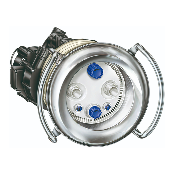
    3 Description Description Composants (21/1) (54) (92) (111) (38/1) Pièce à sceller (21/1) Régulation de débit (92) Pompe (38/1) Commande pneumatique de la pompe (54) Buse (38/2) Commande pneumatique de (111) Régulation d'air l'éclairage Fonction La pompe (92) est reliée par les tuyauteries d'aspiration et de refoulement à...
  • Page 99: Transport Et Stockage Intermédiaire

    4 Transport et stockage intermédiaire Transport et stockage intermédiaire Corrosion due à un stockage dans un environnement humide et sujet aux variations de température ! La condensation peut endommager le bobinage et les pièces métalliques. Stocker la pompe dans un lieu sec et à l´abri des variations de ...
  • Page 100: Installation

    5 Installation Installation Lieu de montage 5.1.1 Installation en plein air Prévoir une simple protection contre la pluie afin d´augmenter la  durée de vie de la pompe. 5.1.2 Bonde d´évacuation de l´eau (doit être installée) Le diamètre de la bonde de fond est calculé selon les critères ...
  • Page 101: Mise En Place

    5 Installation Mise en place Instruction de montage BADU ® Jet primavera: Collier de Poignée de maintien serrage Membrane PVC Enjoliveur en acier inoxydable Béton Pièce à sceller Joints d'étanchéité Carter d'aspiration Piscine structure béton avec membrane PVC Colliers de serrage Poignée de maintien Enjoliveur en acier...
  • Page 102 5 Installation Collier de serrage Poignée de maintien Enjoliveur en acier Membrane PVC inoxydable Paroi de la cuve Pièce à sceller Joints d'étanchéité Carter d'aspiration Piscine à membrane PVC Collier de Poignée de maintien serrage Enjoliveur en acier inoxydable Paroi de la piscine Pièce à...
  • Page 103: Montage De La Pièce À Sceller Dans Une Piscine En Béton

    5 Installation 5.2.1 Montage de la pièce à sceller dans une piscine en béton Veillez à ce que le raccordement de refoulement soit disposé au- dessus du raccordement d'aspiration. Définition de la profondeur d'encastrement: le centre de la pièce à sceller / des buses doit se trouver 30 cm en dessous du niveau d'eau.
  • Page 104 5 Installation Montage sur le coffrage d'une piscine à structure béton Cordon d'étanchéité rond ! Raccordement refoulement EN HAUT ! Raccordement d'aspiration Vis auto taraudeuse Joint à plots Coffrage Coffrage ~240 Fig. 2 Montage du la pièce à sceller dans une piscine à structure béton avec membrane PVC Prière de tenir compte du par.
  • Page 105: Montage De La Pièce À Sceller Dans Une Piscine Polyester, En Acier Ou En Alu

    5 Installation Montage de la pièce à sceller dans une piscine à structure béton carrelée Prière de tenir compte du par. 5.3.3: Alignement de l'anneau de serrage 34 106 Fig. 4 Dans une piscine carrelée, l'épaisseur des carreaux est compensée par un anneau de serrage supplémentaire (28) et des vis auto taraudeuses plus longues (52).
  • Page 106 5 Installation Proposition de montage dans coque polyester/piscine avec membrane PVC Ø7 1) Fixation de la bague de serrage (12x) Fig. 5 Montage de la pièce à sceller dans une coque en polyester Prière de tenir compte du par. 5.2.3: Alignement de l'anneau de serrage 34 106 Piscine polyester Fig.
  • Page 107: Alignement De L'anneau De Serrage

    5 Installation Montage de la pièce à sceller dans une piscine avec membrane PVC Prière de tenir compte du par. 5.2.3: Alignement de l'anneau de serrage 34 106 Piscine avec membrane PVC Fig. 7 5.2.3 Alignement de l'anneau de serrage Les quatre perçages marqués (1) doivent toujours former un angle de 45°...
  • Page 108: Gaine De Protection Et Flexible De La Régulation D'air

    5 Installation 5.2.4 Gaine de protection et flexible de la régulation d'air Faire passer et fixer au-dessus du niveau d'eau la gaine de protection et le flexible de la régulation d'air. 5.2.5 Dimensions des tuyauteries Des conduites d'aspiration trop longues présentent des inconvénients considérables : ...
  • Page 109: Fosse D´installation Du Groupe Motopompe

    5 Installation 5.2.8 Fosse d´installation du groupe motopompe La pose du groupe motopompe doit se faire dans une fosse adjacente à la piscine. Dans l'espace d'installation, veiller à une aération et désaération impeccables et prévoir un écoulement suffisant au niveua du sol.
  • Page 110: Montage Final

    5 Installation Montage final Après le montage de la pièce à sceller (kit de pré assemblage): Collage de la gaine de protection de câble et du flexible de la régulation (Fig. 9). Placer le joint torique (108) dans la pièce á sceller (1) (Fig. 10). Visser les dix vis auto taraudeuses jointes (61) dans le corps de buses.
  • Page 111 5 Installation Les dommages résultant d'une transgression ou d'un montage défectueux, rendent toutes les revendications de garantie et de dommage et intérêts caduques. Aligner l´enjoliveur en acier inoxydable (93.1) sur les plots de centrage en surplomb sur les évidements disponibles dans le carter d'aspiration (93).
  • Page 112 5 Installation 15. Mise en service et hors service de la nage à contre-courant à l´aide des commandes pneumatiques : Pompe MARCHE/ARRET (38/1) - bouton-poussoir de  droite Eclairage MARCHE/ARRET (38/2) - bouton-poussoir de  gauche Régulation de débit de la piscine avec le bouton rotatif (21/1): OUVRIR - rotation vers la gauche ...
  • Page 113 5 Installation Raccordement de refoulement Réserve Gaine de protection de câble ø25 Raccordement d'aspiration Flexible d'air ø20 Fig. 9 102.1 Fig. 10 12/2014 VG 766.2320.050 FR 113...
  • Page 114 5 Installation 93.1 Montage: Démontage: Avec un tournevis, Avec un tournevis replier la languette pointu, replier la vers l'arrière! (2x) languette vers l'avant! (2x) Fig. 11 114 FR VG 766.2320.050 12/2014...
  • Page 115 5 Installation 38/1 38/2 Fig. 12 12/2014 VG 766.2320.050 FR 115...
  • Page 116 5 Installation 21/1 Fig. 13 100/1 106.1 105.1 Fig. 14 116 FR VG 766.2320.050 12/2014...
  • Page 117 5 Installation REFOULEMENT Raccordement collé ASPIRATION Raccordement collé Fig. 15 12/2014 VG 766.2320.050 FR 117...
  • Page 118: Installer La Pompe Et La Raccorder Aux Tuyauteries

    5 Installation Aération et désaération DN 150 (125) (min. 11) Cotes en cm Largeur min. de la fosse 70 cm Monter l'installation de commu- tation au sec et au-dessus du niveau de l'eau Faire passer et fixer le flexible DN 90 de régulation d'air et le bou- ton-poussoir pneumatique Bande de mise à...
  • Page 119: Branchement Électrique

    5 Installation Branchement électrique AVERTISSEMENT! Risque de décharge électrique résultant d´un branchement incorrect ! Respecter les directives VDE et EVU du fournisseur et de  distribution d´énergie. Les pompes pour piscine et leurs volumes de sécurité doivent être  installés conformément à la norme DIN VDE 0100-702. Installer un disjoncteur magnéto thermique permettant l´interruption ...
  • Page 120: Jet Primavera

    5 Installation ® 5.4.1 Raccordement électrique pour BADU Jet primavera Le circuit est pré câblé, les raccordements sont réalisés suivant le  schéma de câblage. Relier les flexibles pneumatiques des boutons poussoirs  pneumatiques au coffret de commande. Raccordement côté bâtiment: ...
  • Page 121: Schéma De Câblage 3~ 400/230 V 50 Hz

    5 Installation 5.4.2 Schéma de câblage 3~ 400/230 V 50 Hz Coffret de commande L1L2 L3 3,15A Pompe 230V 1 2 3 SELV Raccordement - Option pour télécommande L1 L2 L3 N PE (contacts libres de Réseau: 400V 3N AC 50HZ potentiel) Raccordement côté...
  • Page 122: Mise En Service

    6 Mise en service Mise en service Endommagement de la pompe suite à un fonctionnement sans eau ! Assurez-vous que la pompe est remplie d'eau. Cette  recommandation s´applique également au contrôle du sens de rotation. Vérifier le bon fonctionnement de la pompe Après un temps d'arrêt prolongé, vérifier le bon fonctionnement de la pompe à...
  • Page 123: Fonctionnement

    7 Fonctionnement Fonctionnement  La mise en service et hors service de l'installation se fait en appuyant sur la commande pneumatique montée dans le carter en dessous du niveau de l'eau, c.-à-d. qu'il n'y a pas d´activation électrique dans le bassin. La régulation de débit montée au-dessus des buses permet de ...
  • Page 124: Utilisation Du Flexible De Massage

    7 Fonctionnement Utilisation du flexible de massage L'utilisation du flexible de massage, c.-à-d. le massage, devrait se faire uniquement après concertation avec un médecin. Il faut veiller à ce que le flexible de massage ne soit pas utilisé par des enfants. 1.
  • Page 125: Anomalies

    8 Anomalies Anomalies Il est normal que, de temps en temps, des gouttelettes d´eau suintent du joint d´étanchéité. Cela est particulièrement vrai lorsque la pompe est en fonctionnement. Selon la qualité de l'eau et le nombre d'heures de fonctionnement de la pompe, il se peut que le joint d´étanchéité...
  • Page 126: Contrôler La Pompe Après Le Déclenchement D'un Contacteur/Disjoncteur De Protection

    8 Anomalies 8.1.1 Contrôler la pompe après le déclenchement d'un contacteur/disjoncteur de protection Si le moteur est coupé pas le biais du disjoncteur thermique du bobinage ou du dispositif de protection du moteur, suivez ces étapes : 1. Couper l'alimentation électrique de l'installation. 2.
  • Page 127: Maintenance

    9 Maintenance Maintenance Fermer tous les clapets anti-retour et vider les tuyauteries avant  tous travaux de maintenance. Quand? Quoi? Régulièrement Débarrasser l'ouverture d'aspiration des  corps étrangers. Si risque de gel Vidanger en temps voulu la pompe et les ...
  • Page 128: Remplacement Du Projecteur Led

    9 Maintenance Remplacement du projecteur LED 128 FR VG 766.2320.050 12/2014...
  • Page 129 9 Maintenance Mise en place du nouveau projecteur LED et montage de l'installation dans l'ordre inverse. Montage de la régulation d'air, voir p. 115 Fig. 12! 12/2014 VG 766.2320.050 FR 129...
  • Page 130: Caractéristiques Techniques

    10 Caractéristiques techniques Caractéristiques techniques Caractéristiques techniques à ® BADU Jet primavera 50 Hz Surpresseur 21-81/33 G 29° 21-81/34 G29° Débit de refoulement de la pompe (m 400/230 V/ 400 V/ Tension 3N~/1~ 230 V Puissance absorbée P (kW) 3,80/3,90 4,66 3~/1~ Puissance débitée P...
  • Page 131 Oorspronkelijke gebruikershandleiding voor Inbouwtegenstroominstallatie Hauptstraße 1-3 91233 Neunkirchen a. Sand Germany Tel. +49 9123-949-0 Fax +49 9123-949-260 info@speck-pumps.com www.speck-pumps.com 12/2014 VG 766.2320.050 1‘ RE/BA...
  • Page 132 Inhoudsopgave Inhoudsopgave 1 Over dit document ..............135 Omgang met deze handleiding ..........135 Overige relevante documenten ..........135 1.2.1 Symbolen en speciale opmaak ......... 135 2 Veiligheid ..................137 Gebruik volgens bestemming ..........137 2.1.1 Mogelijk onjuist gebruik ..........137 Kwalificaties van het personeel ...........
  • Page 133 Inhoudsopgave 5.1.3 Be- en ontluchting ............ 145 5.1.4 Overdracht van trillingen en geluidsgolven ....145 5.1.5 Benodigde ruimte ............. 145 5.1.6 Bevestigingselementen ..........145 Plaatsing ................146 5.2.1 Montage van het inbouwhuis in een betonnen zwembad ..............148 5.2.2 Montage van de het inbouwhuis in polyester, stalen of aluminium zwembaden ..........
  • Page 134 Inhoudsopgave Alle rechten voorbehouden. De inhoud mag, zonder schriftelijke toestemming, van Speck Pumpen Verkaufsgesellschaft GmbH niet verspreid, vermenigvuldigd, bewerkt of aan derden gegeven worden. Dit document en ook alle documenten in de appendix kunnen veranderen. Technische veranderingen voorbehouden! 134 NL VG 766.2320.050...
  • Page 135: Over Dit Document

    1 Over dit document Over dit document Omgang met deze handleiding Deze handleiding is onderdeel van de tegenstroominstallatie. De installatie is volgens de erkende stand der techniek gebouwd en gecontroleerd. Desondanks kan er bij ondeskundig gebruik, bij onvoldoende onderhoud en bij ongeoorloofde ingrepen gevaar voor lijf en leden of voor materiële schade ontstaan.
  • Page 136 1 Over dit document Om de correcte bediening te verduidelijken zijn belangrijke informatie en technische aanwijzingen speciaal opgemaakt. Symbool Betekenis Uit te voeren handeling bestaande uit één stap  Handelingsinstructie bestaande uit meerdere stappen Neem de volgorde van de stappen in acht. ...
  • Page 137: Veiligheid

    2 Veiligheid Veiligheid Gebruik volgens bestemming Voor inbouw in alle zwembaduitvoeringen als attractie, voor fitness, als golfslag- of bubbelbad, voor onderwatermassage op doktersadvies of om te zwemmen zonder te keren. Tot het bedoelde gebruik behoort ook het in acht nemen van onderstaande informatie: ...
  • Page 138: Veiligheidsvoorschriften

    2 Veiligheid Zorg dat aan onderstaande voorwaarden is voldaan:  – Personeel dat de betreffende kwalificaties nog niet kan aantonen, is passend geïnstrueerd voordat het werkzaamheden aan de installatie uitvoert. – De verantwoordelijkheden van het personeel, b.v. voor werkzaamheden aan het product, aan de elektrische uitrusting of de hydraulische voorzieningen, zijn in overeenstemming met hun kwalificaties en functie-omschrijving vastgelegd.
  • Page 139: Afbeeldingen

    2 Veiligheid Afbeeldingen Houd alle afbeeldingen op de installatie en het pompaggregaat in  leesbare toestand. Overige risico´s 2.7.1 Vallende delen Gebruik uitsluitend passende en in technisch goede staat  verkerende hijs- en hefmiddelen. Begeef u niet onder een zwevende last. ...
  • Page 140: Hete Oppervlakken

    2 Veiligheid 2.7.4 Hete oppervlakken De elektromotor kan een temperatuur bereiken van maximaal 70 °C. Daardoor bestaat gevaar voor verbranding. Raak de motor tijdens bedrijf niet aan.  Laat voor aanvang van werkzaamheden aan de pomp de motor  eerst afkoelen: 2.7.5 Aanzuiggevaar WAARSCHUWING! Onderstaande gevaren kunnen optreden:...
  • Page 141: Voorkomen Van Materiële Schade

    2 Veiligheid Voorkomen van materiële schade 2.9.1 Lekkages en leidingbreuk Het niet in acht nemen van de uithardingstijd van ABS-lijmverbindingen kan leiden tot lekkages en overstromingen. Houd voor ABS-lijmverbindingen een uithardingstijd aan van ten  minste 12 uur. Zorg voor een bodemafvoer. ...
  • Page 142: Oververhitting

    2 Veiligheid 2.9.4 Oververhitting Onderstaande factoren kunnen leiden tot oververhitting van de pomp:  Te hoge druk aan de perszijde  Verkeerd ingestelde motorbeveiligingsschakelaar  Te hoge omgevingstemperatuur Stel de pomp niet in bedrijf met gesloten afsluiters.  Installeer de motorbeveiligingsschakelaar en stel deze correct in. ...
  • Page 143: Beschrijving

    3 Beschrijving Beschrijving Componenten (21/1) (54) (92) (111) (38/1) Inbouwhuis (21/1) Volumeregeling (92) Pomp (38/1) Pneumatische drukknop pomp (54) Nozzles (38/2) Pneumatische drukknop licht (111) Luchtregeling Werking De pomp (92) is d.m.v. de zuig- en persleidingen verbonden met het kunststof inbouwhuis (1). Met de pneumatische drukknop (38/1) wordt de pomp IN/UIT geschakeld.
  • Page 144: Transport En Tijdelijke Opslag

    4 Transport en tijdelijke opslag Transport en tijdelijke opslag Corrosie door opslag in een vochtige omgeving bij wisselende temperaturen! Condens kan inwerken op wikkelingen en metalen delen. Zorg bij tijdelijke opslag voor een droge omgeving met een zo  constant mogelijke temperatuur. Beschadiging of verlies van losse delen! Open de originele verpakking pas bij het inbouwen resp.
  • Page 145: Installatie

    5 Installatie Installatie Inbouwlocatie 5.1.1 Plaatsing in de buitenlucht Voorzie in een eenvoudige regenbescherming om de levensduur  van de pomp te verlengen. 5.1.2 Bodemafvoer (moet aanwezig zijn) Bepaal de afmetingen van de bodemafvoer naar onderstaande  criteria: – Afmetingen van het zwembad –...
  • Page 146: Plaatsing

    5 Installatie Plaatsing ® Inbouwinstructie BADU Jet primavera: Handgreep Folie Spanring Roestvrijstalen afscherming Beton Inbouwhuis Afdichtingen Aanzuigafscherming Betonnen zwembad met folie Handgreep Spanringen Roestvrijstalen Tegels afscherming Beton Inbouwhuis Afdichting Aanzuigafscherming Betonnen zwembad betegeld 146 NL VG 766.2320.050 12/2014...
  • Page 147 5 Installatie Handgreep Spanring Folie Roestvrijstalen afscherming Zwembadwand Inbouwhuis Afdichtingen Aanzuigafscherming Foliezwembad Handgreep Spanring Roestvrijstalen afscherming Zwembadwand Inbouwhuis Afdichtingen Aanzuigafscherming Polyesterzwembad 12/2014 VG 766.2320.050 NL 147...
  • Page 148: Montage Van Het Inbouwhuis In Een Betonnen Zwembad

    5 Installatie 5.2.1 Montage van het inbouwhuis in een betonnen zwembad Zorg persaansluiting boven zuigaansluiting wordt gepositioneerd. Bepaling van de inbouwdiepte: het midden van het inbouwhuis/ de nozzles moeten zich 30 cm onder de waterspiegel bevinden. Plaats de noppenafdichting (26) in de behuizing (1), lijn het inbouwnuis uit en bevestig deze met 4 zelftappers aan de bekisting.
  • Page 149: Installatie

    5 Installatie Montage aan de bekisting voor betonnen zwembaden Afdichtkoord ! Persaansluiting BOVEN ! Zuigaansluiting Zelftapper Noppenafdichting Bekisting Bekisting ~240 Afb.2 Montage van het inbouwhuis in betonnen zwembaden met foliebekleding Zie 5.2.3: Uitlijning van de spanring 34 106 Folie Afb.3 12/2014 VG 766.2320.050 NL 149...
  • Page 150: Montage Van De Het Inbouwhuis In Polyester, Stalen Of Aluminium Zwembaden

    5 Installatie Montage van het inbouwhuis in betegelde betonnen zwembaden Zie 5.3.3: Uitlijning van de spanring 34 106 Afb.4 In een betegeld zwembad wordt de tegeldikte gecompenseerd met een extra spanring (28) en langere zelftappers (52). Deze delen zijn optioneel verkrijgbaar in de aanvullende kit. 5.2.2 Montage van de het inbouwhuis in polyester, stalen of aluminium zwembaden...
  • Page 151 5 Installatie Wanduitsparing voor polyester zwembaden/foliezwembaden Ø7 1) Bevestiging spanring (12x) Afb.5 Montage van het inbouwhuis in een polyester zwembad Zie 5.2.3: Uitlijning van de spanring 34 106 Polyesterzwembad Afb.6 12/2014 VG 766.2320.050 NL 151...
  • Page 152: Uitlijning Van De Spanring

    5 Installatie Montage van het inbouwhuis in een foliezwembad Zie 5.2.3: Uitlijning van de spanring 34 106 Foliezwembaden Afb.7 5.2.3 Uitlijning van de spanring De vier met (1) gemarkeerde boringen moeten altijd onder een hoek van 45° staan met de middellijn. Afb.8 5.2.4 Beschermslang en slang voor luchtregeling...
  • Page 153: Leiding Dimensioneren

    5 Installatie 5.2.5 Leiding dimensioneren Te lange zuigleidingen hebben aanzienlijke nadelen:  Een hogere weerstand, waardoor slechter aanzuigen en een grotere kans op cavitatie.  Een langere aanzuigtijd (tot 12 min.). LET OP! Het inbouwhuis en de koppelingen zijn van ABS. Houd voor verlijmingen een uithardingstijd aan van ten minst 12 uur! 5.2.6...
  • Page 154: Eindmontage

    5 Installatie Eindmontage Na montage van het inbouwhuis (voormontageset): Verlijm de kabelbeschermslang en de buitenste luchtslang (Afb.9). Plaats de O-ring (108) in het inbouwhuis (1) (Afb.10). Draai de tien meegeleverde zelftappers (61) in het nozzlehuis. Druk voorgemonteerde nozzlehuis (102.1) tegen inbouwhuis (1) (Afb.10).
  • Page 155 5 Installatie centreernoppen uit op de uitsparingen van de aanzuigafscherming (93) en met de hand aan elkaar drukken. Let op de markering "OBEN" (BOVEN) op de roestvrijstalen afscherming. Buig de twee buiglippen aan de zijkant met een schroevendraaier om naar achteren om de afscherming vast te zetten (Afb.11).
  • Page 156 5 Installatie OPEN - linksom draaien  DICHT - rechtsom draaien  Persaansluiting Reserve Kabelbeschermslang ø25 Zuigaansluiting Luchtslang ø20 Afb.9 102.1 Afb.10 156 NL VG 766.2320.050 12/2014...
  • Page 157 5 Installatie 93.1 Montage: Demontage: Met spitse schroevendraaier schroevendraaier lip naar achteren lip naar voren ombuigen! (2x) terugbuigen! (2x) Afb.11 12/2014 VG 766.2320.050 NL 157...
  • Page 158 5 Installatie 38/1 38/2 Afb.12 158 NL VG 766.2320.050 12/2014...
  • Page 159 5 Installatie 21/1 Afb.13 100/1 106.1 105.1 Afb.14 12/2014 VG 766.2320.050 NL 159...
  • Page 160 5 Installatie PERS kleefverbinding ZUIG kleefverbinding Afb.15 160 NL VG 766.2320.050 12/2014...
  • Page 161: Pomp Plaatsen En Op Leiding Aansluiten

    5 Installatie Be- en ontluchting DN 150 (125) (min. 11) Afmetingen in cm Schachtbreedte min. 70 cm Schakelinstallatie in een droge ruimte en boven de waterspiegel monteren Voer de slang voor de luchtrege- DN 90 ling en de pneumatische druk- knoppen tot boven de water- Aardstrip spiegel en bevestig deze...
  • Page 162: Elektrische Aansluiting

    5 Installatie Elektrische aansluiting WAARSCHUWING! Gevaar voor een elektrische schok door ondeskundige aansluiting! Neem de VDE- en EVU-voorschriften van het energiebedrijf in acht.  Installeer pompen voor zwembaden en beschermingszones  conform DIN VDE 0100-702. Installeer een scheidingsvoorziening voor het lichtnet met ten ...
  • Page 163: Schakelschema 3~ 400/230 V 50 Hz

    5 Installatie Zie voor meer informatie het aansluitschema. Deze onderdelen zijn niet bij levering inbegrepen en moeten voor installatie van het systeem op locatie worden aangelegd. 5.4.2 Schakelschema 3~ 400/230 V 50 Hz Schakelkast L1L2 L3 3,15A Pomp 230V 1 2 3 SELV Aansluiting - optie voor L1 L2 L3 N PE...
  • Page 164: Inbedrijfstelling

    6 Inbedrijfstelling Inbedrijfstelling Beschadiging van de pomp door drooglopen! Zorg dat de pomp altijd met water is gevuld. Dat geldt ook tijdens  controle van de draairichting. Soepel lopen van de pomp controleren Na een langere periode van stilstand moet in uitgeschakelde en spanningsloze toestand worden gecontroleerd of de pomp soepel loopt.
  • Page 165: Gebruik

    7 Gebruik Gebruik  Het in- en uitschakelen van de installatie gebeurt met de onder de waterspiegel afscherming ingebouwde pneumatische drukknop, d.w.z. bevindt zich geen elektrische bedieningseenheid in het zwembad. Met de volumeregeling die boven de nozzles is aangebracht, kan de ...
  • Page 166: Gebruik Van De Massageslang

    7 Gebruik Gebruik van de massageslang Gebruik van de massageslang, d.w.z. het masseren, is uitsluitend toegestaan in overleg met een arts. Er moet op worden gelet dat de massageslang niet door kinderen wordt gebruikt. 1. Draai de volumeregeling van de tegenstroominstallatie terug. 2.
  • Page 167: Storingen

    8 Storingen Storingen Het is normaal dat er van tijd tot tijd enkele druppels water door de mechanical seal gaat lekken. Dat geldt met name tijdens de inlooptijd. Afhankelijk van de waterkwaliteit en het aantal bedrijfsuren kan de mechanical seal gaan lekken. Wanneer er permanent water vrijkomt, moet de mechanical seal ...
  • Page 168: Pomp Controleren Na Het Inwerking Zetten Van De Beveiligingsschakelaar

    9 Onderhoud 8.1.1 Pomp controleren na het inwerking zetten van de beveiligingsschakelaar Voer onderstaande handelingen uit wanneer de motor door het wikkelingsbeschermingscontact of de motorbeveiligingsschakelaar is uitgeschakeld: 1. Scheid de installatie van het lichtnet. 2. Draai de motoras aan de ventilatorzijde met een schroevendraaier door om te controleren of deze soepel loopt.
  • Page 169: Onderhoud

    9 Onderhoud Onderhoud sluit voorafgaand aan onderhoudswerkzaamheden alle afsluiters en  maak alle leidingen leeg. Wanneer? Wat? Regelmatig Aanzuigopening vrijmaken van vreemde  voorwerpen. Bij bevriezingsgevaar Maak de pomp en leidingen die kunnen  bevriezen tijdig leeg. Neem na beëindiging van de onderhoudswerkzaamheden alle ...
  • Page 170: Vervangen Van De Led-Spot

    9 Onderhoud Vervangen van de LED-spot 170 NL VG 766.2320.050 12/2014...
  • Page 171 9 Onderhoud Aanbrengen van de nieuwe LED-spot en het weer in elkaar zetten van de installatie in omgekeerde volgorde. Zie voor montage van de luchtregeling p. 158, Afb.12! 12/2014 VG 766.2320.050 NL 171...
  • Page 172: Technische Gegevens

    10 Technische gegevens Technische gegevens Technische gegevens bij 50 Hz BADU ® Jet primavera Jet-pomp 21-81/33 G 29° 21-81/34 G 29° Capaciteit van de pomp (m 400/230 V/ 400 V/ Spanning 3N~/1~ 230 V Opgenomen vermogen P (kW) 3,80/3,90 4,66 3~/1~ Afgegeven vermogen P (kW)
  • Page 173 Manuale d'istruzioni originale per Gruppo di nuoto controcorrente da incasso Hauptstraße 1-3 91233 Neunkirchen a. Sand Germany Tel. +49 9123-949-0 Fax +49 9123-949-260 info@speck-pumps.com www.speck-pumps.com 12/2014 VG 766.2320.050 1’ RE/BA...
  • Page 174 Indice Indice 1 Informazioni sul presente documento ........177 Utilizzo delle presenti istruzioni ..........177 Altra documentazione valida ..........177 1.2.1 Simboli e mezzi illustrativi ......... 177 2 Sicurezza ..................179 Uso conforme ..............179 2.1.1 Possibili usi errati ............. 179 Qualifica del personale ............
  • Page 175 1 Informazioni sul presente documento 5.1.3 Ventilazione e scarico dell'aria ......... 187 5.1.4 Trasmissione di vibrazioni sonore intrinseche e propagantesi attraverso l'aria ........187 5.1.5 Riserva di spazio ............187 5.1.6 Elementi di fissaggio ..........187 Installazione ................. 188 5.2.1 Montaggio della parte da murare in una vasca di cemento armato ............
  • Page 176 Indice Tutti i diritti riservati. I contenuti non potranno essere diffusi, riprodotti, modificati né ceduti a terzi senza il consenso scritto di Speck Pumpen Verkaufsgesellschaft GmbH. Questo documento e tutti i documenti contenuti nell'allegato non sono soggetti ad alcuna revisione!
  • Page 177: Informazioni Sul Presente Documento

    1 Informazioni sul presente documento Informazioni sul presente documento Utilizzo delle presenti istruzioni Queste istruzioni sono parte dell'impianto di nuoto controcorrente. L'impianto è stato prodotto e controllato secondo le regole tecniche riconosciute ed approvate. Il suo utilizzo non conforme, la sua manutenzione insufficiente o interventi non consentiti su di esso possono tuttavia comportare pericoli anche letali o danni materiali.
  • Page 178 1 Informazioni sul presente documento Per illustrare e chiarire l'uso corretto, informazioni importanti ed avvertenze tecniche sono evidenziate in modo particolare. Simbolo Significato Singola azione da compiere  Istruzioni per una serie di azioni da compiere Rispettare l'ordine delle azioni. ...
  • Page 179: Sicurezza

    2 Sicurezza Sicurezza Uso conforme Montaggio in tutte le esecuzioni di piscina come attrazione, per fitness, come bagno con onde o perle d'aria, per il massaggio subacqueo secondo consiglio medico, per nuotare senza invertire la direzione. Dell'uso conforme fa parte anche il rispetto delle seguenti informazioni: ...
  • Page 180: Disposizioni Di Sicurezza

    2 Sicurezza Assicurare che siano soddisfatte le seguenti condizioni:  – Il personale non ancora in possesso della qualifica necessaria viene debitamente addestrato prima di essere incaricato di svolgere compiti tipici dell'impianto. – Le competenze del personale, ad esempio per i lavori sul prodotto, sull'equipaggiamento elettrico o sui dispositivi idraulici, sono definite in funzione della qualifica e della descrizione del posto di lavoro.
  • Page 181: Targhette

    2 Sicurezza Targhette Mantenere tutte le targhette dell'impianto e del gruppo pompa in  uno stato leggibile. Rischi conseguenti 2.7.1 Caduta di parti Usare solo apparecchi di sollevamento e dispositivi di aggancio o di  imbracatura adatti ed in uno stato tecnico regolare. Non sostare sotto carichi sospesi.
  • Page 182: Superfici Ad Alta Temperatura

    2 Sicurezza 2.7.4 Superfici ad alta temperatura Il motore elettrico può raggiungere temperature fino a 70 °C. Ne deriva il pericolo di ustioni. Non toccare il motore in funzione.  Far raffreddare il motore prima di svolgere lavori sulla pompa. ...
  • Page 183: Evitare Danni Materiali

    2 Sicurezza Evitare danni materiali 2.9.1 Perdite e rottura di tubi La mancata osservanza dei tempi di indurimento degli incollaggi di ABS può causare perdite ed allagamenti. Osservare un tempo di indurimento degli incollaggi di ABS di  almeno 12 h. Predisporre un sufficiente scarico di fondo.
  • Page 184: Surriscaldamento

    2 Sicurezza 2.9.4 Surriscaldamento I seguenti fattori possono portare ad un surriscaldamento della pompa:  Pressione eccessiva sul lato di mandata  Salvamotore regolato in modo errato  Temperatura ambiente eccessiva Non far funzionare la pompa con valvole chiuse  Installare e regolare correttamente il salvamotore.
  • Page 185: Descrizione

    3 Descrizione Descrizione Componenti (21/1) (54) (92) (111) (38/1) Corpo da murare (21/1) Regolazione della portata (92) Pompa (38/1) Pulsante pneumatico pompa (54) Ugelli (38/2) Pulsante pneumatico luce (111) Regolazione dell'aria Funzione La pompa (92) è collegata al corpo da murare di plastica (1) mediante il tubo di aspirazione e di mandata.
  • Page 186: Trasporto Ed Immagazzinamento Temporaneo

    4 Trasporto ed immagazzinamento temporaneo Trasporto ed immagazzinamento temporaneo Corrosione a causa dell'immagazzinamento in aria umida e soggetta a sbalzi termici! L'acqua di condensa può attaccare gli avvolgimenti e le parti metalliche. Immagazzinare temporaneamente la pompa in un ambiente  asciutto ed a temperatura possibilmente costante.
  • Page 187: Installazione

    5 Installazione Installazione Luogo di montaggio 5.1.1 Installazione all'aperto Per aumentare la durata utile della pompa predisporre un semplice  parapioggia. 5.1.2 Scarico di fondo (deve essere presente) Dimensionare lo scarico di fondo secondo i seguenti criteri:  – Grandezza della piscina –...
  • Page 188: Installazione

    5 Installazione Installazione ® Indicazioni di montaggio BADU Jet primavera: Maniglione di sostegno Liner Anello elastico Copertura di acciaio inox Cemento armato Corpo da murare Guarnizioni Mascherina/Copertura di aspirazione Vasca di cemento armato con liner impermeabile Maniglione di sostegno Anelli di elastici Piastrelle Copertura di acciaio inox...
  • Page 189 5 Installazione Maniglione di sostegno Anello elastico Liner Copertura di Parete della vasca acciaio inox Corpo da murare Guarnizioni Mascherina/Copertura di aspirazione Vasca prefabbricata con liner impermeabile Maniglione di sostegno Anello elastico Copertura di Parete della vasca acciaio inox Corpo da murare Guarnizioni Mascherina/Copertura di aspirazione Vasca di poliestere...
  • Page 190: Montaggio Della Parte Da Murare In Una Vasca Di Cemento Armato

    5 Installazione 5.2.1 Montaggio della parte da murare in una vasca di cemento armato Si osservi che il raccordo di mandata deve essere ubicato in alto, sopra il raccordo di aspirazione. Determinazione della profondità di montaggio: il centro del corpo da murare / degli ugelli deve trovarsi 30 cm sotto il livello dell'acqua.
  • Page 191 5 Installazione Montaggio su cassaforma per vasca di cemento armato Guarnizione a sezione circolare ! Raccordo di mandata IN ALTO ! Raccordo di aspirazione Vite autofilettante Guarnizione a noduli Cassaforma Cassaforma ~ 240 Fig. 2 Montaggio della parte da murare in una vasca di cemento armato rivestita da liner impermeabile Osservare il punto 5.2.3: Posizionamento dell'anello elastico 34 106...
  • Page 192: Montaggio Della Parte Da Murare In Una Vasca Di Poliestere, Di Acciaio O Di Alluminio

    5 Installazione Montaggio della parte da murare in una vasca di cemento armato piastrellata Osservare il punto 5.3.3: Posizionamento dell'anello elastico 34 106 Fig. 4 In una vasca piastrellata, lo spessore delle piastrelle viene compensato con un anello elastico supplementare (28) e con viti autofilettanti più lunghe (52).
  • Page 193 5 Installazione Suggerimento di montaggio in vasca di poliestere/vasca prefabbricata con liner impermeabile Ø7 Fig. 5 1) Fissaggio anello elastico (12x) Fig. 5 Montaggio della parte da murare in una vasca di poliestere Osservare il punto 5.2.3: Posizionamento dell'anello elastico 34 106 Vasca di poliestere Fig.
  • Page 194: Posizionamento Dell'anello Elastico

    5 Installazione Montaggio della parte da murare in una vasca prefabbricata con liner Osservare il punto 5.2.3: Posizionamento dell'anello elastico 34 106 Vasca prefabbricata Fig. 7 5.2.3 Posizionamento dell'anello elastico I quattro fori (1) devono essere sempre a 45° rispetto all'asse centrale. Fig.
  • Page 195: Dimensionamento Del Tubo

    5 Installazione 5.2.5 Dimensionamento del tubo Tubi di aspirazione di lunghezza eccessiva comportano notevoli svantaggi:  Resistenza maggiore, per cui comportamento di aspirazione peggiore e rischio di cavitazione maggiore. Tempo di aspirazione più lungo (fino a 12 min).  ATTENZIONE! Il corpo da murare ed i raccordi sono di ABS. È...
  • Page 196: Pozzetto Della Pompa

    5 Installazione 5.2.8 Pozzetto della pompa Si raccomanda di installare il gruppo pompa in un pozzetto confinante con la vasca. Nello spazio di installazione è necessario assicurare una ventilazione ed uno scarico dell'aria regolari e predisporre un sufficiente scarico di fondo. Osservare le dimensioni dei tubi. Nel pozzetto della pompa deve essere presente un attacco per la compensazione del potenziale.
  • Page 197: Finitura

    5 Installazione Finitura Dopo il montaggio della parte da murare (kit di montaggio preliminare): Incollare il tubo flessibile di protezione dei cavi ed il tubo flessibile di protezione esterna del tubo dell'aria (fig. 9). Applicare l'O-Ring (108) nel corpo da murare (1) (fig. 10). Avvitare dieci viti...
  • Page 198 5 Installazione I danni causati dalla mancata osservanza o da un montaggio erroneo o inappropriato non sono coperti da alcuna garanzia e da alcun diritto di risarcimento danni. Posizionare la copertura di acciaio inox (93.1) con i noduli di centraggio sulle cavità presenti sulla copertura di aspirazione (93) e unire a pressione manualmente.
  • Page 199 5 Installazione 15. Accensione e spegnimento dalla vasca con i pulsanti pneumatici: Pompa On/Off (38/1) - pulsante destro  Luce On/Off (38/2) - pulsante sinistro  Regolazione della portata dalla vasca con la manopola (21/1): APERTURA - rotazione in senso antiorario ...
  • Page 200 5 Installazione Raccordo di mandata Riserva Tubo di protezione dei cavi ø 25 Raccordo di aspirazione Tubo di protezione del tubo dell'aria ø 20 Fig. 9 102.1 Fig. 10 200 IT VG 766.2320.050 12/2014...
  • Page 201 5 Installazione 93.1 Montaggio: Smontaggio: Con un cacciavite Con un cacciavite ripiegare la linguetta a punta riaprire la (2x) verso il lato linguetta (2x) verso posteriore! il lato anteriore! Fig. 11 12/2014 VG 766.2320.050 IT 201...
  • Page 202 5 Installazione 38/1 38/2 Fig. 12 202 IT VG 766.2320.050 12/2014...
  • Page 203 5 Installazione 21/1 Fig. 13 100/1 106.1 105.1 Fig. 14 12/2014 VG 766.2320.050 IT 203...
  • Page 204 5 Installazione MANDATA Raccordo incollato ASPIRAZIONE Raccordo incollato Fig. 15 204 IT VG 766.2320.050 12/2014...
  • Page 205: Installazione Della Pompa E Collegamento Al Tubo

    5 Installazione Ventilazione e scarico dell'aria DN 150 (125) (min. 11) Quote in cm Larghezza del pozzetto min. 70 cm Montare il comando in am- biente asciutto e sopra il livello dell'acqua DN 90 Condurre e fissare i tubi di regolazione dell'aria e dei Fascia di messa a terra pulsanti pneumatici sopra il...
  • Page 206: Collegamento Elettrico

    5 Installazione Collegamento elettrico AVVERTENZA! Pericolo di folgorazione a causa di un collegamento improprio! Osservare le disposizioni VDE e dell'azienda elettrica locale.  Installare le pompe per piscine e le loro aree di sicurezza  conformemente a DIN VDE 0100-702. Installare una valvola di sezionamento per staccare la tensione di ...
  • Page 207: Schema Elettrico 3 ~ 400 / 230 V, 50 Hz

    5 Installazione 5.4.2 Schema elettrico 3 ~ 400 / 230 V, 50 Hz Quadro elettrico L1L2 L3 3,15A Pompa 230V 1 2 3 SELV Connettore opzionale per L1 L2 L3 N PE telecomando Rete: 400 V 3 N AC 50 Hz (contatti liberi) Collegamento in sede di montaggio Pompa...
  • Page 208: Messa In Servizio

    6 Messa in servizio Messa in servizio Danneggiamento della pompa dovuto al funzionamento a secco! Assicurare che la pompa sia sempre piena d'acqua. Ciò vale anche  per il controllo del verso di rotazione. Controllo della scorrevolezza della pompa Dopo un lungo periodo di fermo è necessario controllare la scorrevolezza della pompa spenta e con tensione staccata.
  • Page 209: Funzionamento

    7 Funzionamento Funzionamento  L'impianto si accende e si spegne premendo il pulsante pneumatico sommerso integrato nella copertura, cioè non vi sono unità di azionamento elettriche nella vasca.  Con la regolazione della portata montata sopra gli ugelli si può regolare la potenza.
  • Page 210: Utilizzo Del Tubo Di Massaggio

    7 Funzionamento Utilizzo del tubo di massaggio Si raccomanda di utilizzare il tubo di massaggio solo dopo aver consultato il medico. Assicurarsi che il tubo di massaggio non venga utilizzato da bambini. 1. Ridurre la portata nell'impianto di nuoto controcorrente. 2.
  • Page 211: Guasti

    8 Guasti Guasti Di tanto in tanto è normale che qualche goccia d'acqua fuoriesca dalla tenuta meccanica. Ciò si verifica specialmente durante il periodo di rodaggio. La tenuta meccanica può diventare non piu´ ermetica a seconda delle proprietà dell'acqua e del numero di ore di funzionamento. In caso di fuoriuscita permanente di acqua sostituire la tenuta ...
  • Page 212: Controllo Della Pompa In Seguito All'intervento Di Un Contatto/Interruttore Di Sicurezza

    8 Guasti 8.1.1 Controllo della pompa in seguito all'intervento di un contatto/interruttore di sicurezza Se il motore è stato spento da un contatto di sicurezza dell'avvolgimento o da salvamotore, adottare i seguenti provvedimenti: 1. Staccare l'impianto dalla tensione di alimentazione. 2.
  • Page 213: Manutenzione

    9 Manutenzione Manutenzione Prima di svolgere lavori di manutenzione chiudere tutti gli organi di  chiusura e svuotare i tubi. Quando? Che cosa? Regolarmente Togliere i corpi estranei dall'apertura di  aspirazione. In caso di pericolo Svuotare tempestivamente la pompa ed i ...
  • Page 214: Sostituzione Del Proiettore A Led

    9 Manutenzione Sostituzione del proiettore a LED 214 IT VG 766.2320.050 12/2014...
  • Page 215 9 Manutenzione Montaggio del nuovo proiettore a LED e riassemblaggio dell'impianto in ordine inverso. Montaggio della regolazione dell'aria: vedere fig. 12 a pag. 201! 12/2014 VG 766.2320.050 IT 215...
  • Page 216: Dati Tecnici

    10 Dati tecnici Dati tecnici Dati tecnici a 50 Hz BADU ® Jet primavera Pompa Jet 21-81/33 G 29° 21-81/34 G 29° Portata della pompa (m³/h) 400/230 V/ 400 V/ Tensione 3N~/1~ 230 V Potenza assorbita P [kW] 3,80/3,90 4,66 3N~/1~ Potenza resa P [kW]...
  • Page 217 Instrucciones para el manejo originales para Dispositivo contra corriente para montaje en piscinas Hauptstraße 1-3 91233 Neunkirchen a. Sand Germany Tel. +49 9123-949-0 Fax +49 9123-949-260 info@speck-pumps.com www.speck-pumps.com 12/2014 VG 766.2320.050 1’ RE/BA...
  • Page 218 Índice de contenidos Índice de contenidos 1 Acerca de este documento ............221 Uso de estas instrucciones ..........221 Documentos convalidados ........... 221 1.2.1 Símbolos y medios de representación...... 221 2 Seguridad ..................223 Utilización según prescripción ..........223 2.1.1 Posible mal uso ............223 Cualificación del personal ............
  • Page 219 Índice de contenidos 5.1.3 Ventilación y purga de aire ........231 5.1.4 Transmisión de sonido del cuerpo y del aire .... 231 5.1.5 Reserva de espacio ..........231 5.1.6 Elementos de fijación ..........231 Instalación ................232 5.2.1 Montaje de la carcasa para montaje empotrado en una piscina de hormigón ........
  • Page 220 Todos los derechos reservados. Los contenidos de este documento no podrán difundirse, editarse ni transmitirse a terceros sin la autorización escrita de Speck Pumpen. Este documento así como todos los documentos contenidos en el anexo no han de sufrir modificaciones.
  • Page 221: Acerca De Este Documento

    1 Acerca de este documento Acerca de este documento Uso de estas instrucciones Estas instrucciones forman parte del dispositivo contracorriente para piscinas. El dispositivo fue fabricado y comprobado de acuerdo con las normas tecnológicas aceptadas. Sin embargo, el uso indebido, el mantenimiento insuficiente o intervenciones inadecuadas pueden causar riesgos para la vida y la integridad física personal o daños a la propiedad.
  • Page 222 1 Acerca de este documento Símbolo de Aviso Significado advertencia – Indicaciones para la prevención de daños materiales, para la comprensión o para la optimización de los procesos del trabajo. A fin de obtener un correcto manejo, las informaciones y las indicaciones técnicas importantes están especialmente realzadas.
  • Page 223: Seguridad

    2 Seguridad Seguridad Utilización según prescripción Para el montaje en todas las versiones de piscinas como atractivo, para el entrenamiento físico, como baño de olas o burbujas, para el masaje subacuático según consejo médico, para nadar sin volverse. Para la utilización según prescripción se deberá tener en cuenta la siguiente información: ...
  • Page 224: Prescripciones De Seguridad

    2 Seguridad – Las responsabilidades del personal, p.ej. para trabajos en el producto, en el equipamiento eléctrico o los dispositivos hidráulicos se determinan en función de su cualificación y la descripción del puesto de trabajo. – El personal ha leído estas instrucciones y entendido los pasos de trabajo necesarios.
  • Page 225: Riesgos Residuales

    2 Seguridad Riesgos residuales 2.7.1 Caída de componentes Utilizar únicamente elevadores y medios de sujeción de carga  adecuados y técnicamente impecables. No permanecer debajo de cargas suspendidas.  2.7.2 Componentes giratorios Peligro de cizallamiento y aplastamiento debido a componentes giratorios abiertos.
  • Page 226: Superficies Calientes

    2 Seguridad 2.7.4 Superficies calientes El motor eléctrico puede alcanzar una temperatura de hasta 70 °C. Existe peligro de quemadura. No tocar el motor durante el funcionamiento.  Antes de trabajos en la bomba dejar primero enfriar el motor.  2.7.5 Peligro por aspiración ¡ADVERTENCIA! Peligros que pueden surgir:...
  • Page 227: Prevención De Daños Materiales

    2 Seguridad Prevención de daños materiales 2.9.1 Inestanqueidad y rotura de tuberías El no cumplimiento del tiempo de endurecimiento de los pegamentos ABS puede dar lugar a inestanqueidad e inundaciones. Atenerse al tiempo de endurecimiento de por lo menos 12 horas de ...
  • Page 228: Sobrecalentamiento

    2 Seguridad 2.9.4 Sobrecalentamiento Factores que pueden dar lugar a un sobrecalentamiento de la bomba:  Presión muy alta en el lado de presión  Guardamotor mal ajustado  Temperatura ambiente muy alta No manejar la bomba con las válvulas cerradas. ...
  • Page 229: Descripción

    3 Descripción Descripción Componentes (21/1) (54) (92) (111) (38/1) Carcasa para montaje (21/1) Regulación de cantidades empotrado (92) Bomba (38/1) Pulsador neumático bomba (54) Boquillas (38/2) Pulsador neumático luz (111) Regulación del aire Funcionamiento La bomba (92) está conectada a través de la tubería de aspiración e impulsión con la carcasa para montaje empotrado de material sintético (1).
  • Page 230: Transporte Y Almacenamiento Intermedio

    4 Transporte y almacenamiento intermedio Transporte y almacenamiento intermedio ¡Corrosión mediante almacenamiento en aire húmedo a diferentes temperaturas! El agua condensada puede corroer los bobinados y las partes de metal. Almacenar provisionalmente la bomba en un entorno seco a una ...
  • Page 231: Instalación

    5 Instalación Instalación Lugar de instalación 5.1.1 Instalación al aire libre Para aumentar la vida de la bomba, prever una protección contra la  lluvia simple. 5.1.2 Drenaje de fondo (debe estar disponible) Dimensionar el tamaño del drenaje de fondo según siguientes ...
  • Page 232: Instalación

    5 Instalación Instalación ® Indicación de montaje BADU Jet primavera: Agarradero Liner Anillo tensor Placa de acero inoxidable Hormigón Carcasa para montaje empotrado Juntas Placa de aspiración Piscinas de hormigón con liner Anillos Agarradero tensores Placa de acero Azulejo inoxidable Hormigón Carcasa para montaje empotrado...
  • Page 233 5 Instalación Agarradero Anillo tensor Liner Placa de acero inoxidable Pared de la piscina Carcasa para montaje empotrado Juntas Placa de aspiración Piscinas liner Agarradero Anillo tensor Placa de acero inoxidable Pared de la piscina Carcasa para montaje empotrado Juntas Placa de aspiración Piscinas de poliéster 12/2014...
  • Page 234: Montaje De La Carcasa Para Montaje Empotrado En Una Piscina De Hormigón

    5 Instalación 5.2.1 Montaje de la carcasa para montaje empotrado en una piscina de hormigón Asegúrese de que la conexión de presión esté dispuesta arriba, por encima de la conexión de aspiración. Determinación de la profundidad de montaje: El centro de la carcasa para montaje empotrado / de las boquillas debe estar 30 cm por debajo del nivel del agua.
  • Page 235 5 Instalación Montaje en encofrado para piscinas de hormigón Cuerda redonda obturante ¡ Conexión de presión ARRIBA ! Conexión de aspiración Tornillo con rosca cortante Junta con motas Encofrado Encofrado ~240 Fig. 2 Montaje de la carcasa para montaje empotrado en una piscina de hormigón con revestimiento liner Por favor tener en cuenta 5.2.3: Alineación del anillo tensor 34 106...
  • Page 236 5 Instalación Montaje de la carcasa para montaje empotrado en una piscina de hormigón con azulejos Por favor tener en cuenta 5.3.3: Alineación del anillo tensor 34 106 Fig. 4 En una piscina con azulejos el grosor del azulejo se compensa con un anillo tensor adicional (28) y tornillos con rosca cortante (52) más largos.
  • Page 237 5 Instalación Abertura para piscinas de poliéster/piscinas liner Ø7 1) Fijación de anillo tensor (12x) Fig. 5 Montaje de la carcasa para montaje empotrado en una piscina de poliéster Por favor tener en cuenta 5.2.3: Alineación del anillo tensor 34 106 Piscinas de poliéster Fig.
  • Page 238: Alineación Del Anillo Tensor

    5 Instalación Montaje de la carcasa para montaje empotrado en una piscina liner Por favor tener en cuenta 5.2.3: Alineación del anillo tensor 34 106 Piscinas de liner Fig .7 5.2.3 Alineación del anillo tensor Los cuatro taladros marcados con (1) deben siempre estar en ángulo de 45°...
  • Page 239: Montaje De La Tubería

    5 Instalación peligro de cavitación  Mayor tiempo de aspiración (hasta 12 min). ¡ATENCIÓN! La carcasa para montaje empotrado y las uniones a rosca son de ABS. ¡Tener en cuenta un tiempo de endurecimiento del pegamento de al menos 12 horas! 5.2.6 Montaje de la tubería Mantener rectas y lo más cortas posibles las tuberías de aspiración...
  • Page 240: Montaje Acabado

    5 Instalación Montaje acabado Después de montar la carcasa para montaje empotrado (kit premontaje): Pegamento del tubo de protección para cables y el tubo de conducción de aire externo (Fig. 9). Poner el anillo toroidal (108) en la carcasa para montaje empotrado (1) (Fig.
  • Page 241 5 Instalación Para los daños resultantes de la violación o de una instalación incorrecta, se anulan todos los derechos de garantía y de indemnización por daños y perjuicios. Alinear la placa de acero inoxidable (93.1) con las motas de centraje salientes en las escotaduras de la placa de aspiración (93).
  • Page 242 5 Instalación 15. Conexión y desconexión desde la piscina con pulsadores neumáticos: Bomba ON/OFF (38/1) - pulsador derecho  Luz ON/OFF (38/2) - pulsador izquierdo  Regulación de cantidades desde la piscina con regulador giratorio (21/1): ABIERTA - giro a la izquierda ...
  • Page 243 5 Instalación Conexión de presión Reserva Tubo de protección para cables ø25 Conexión de aspiración Tubo de conducción de aire ø20 Fig. 9 102.1 Fig. 10 12/2014 VG 766.2320.050 ES 243...
  • Page 244 5 Instalación 93.1 Montaje: Desmontaje: ¡Doblar con ¡Con atornillador atornillador puntiagudo doblar la la lengüeta hacia lengüeta de atrás! (2 veces) vuelta hacia delante! (2 veces) Fig. 11 244 ES VG 766.2320.050 12/2014...
  • Page 245 5 Instalación 38/1 38/2 Fig. 12 12/2014 VG 766.2320.050 ES 245...
  • Page 246 5 Instalación 21/1 Fig. 13 100/1 106.1 105.1 Fig. 14 246 ES VG 766.2320.050 12/2014...
  • Page 247 5 Instalación PRESIÓN Conexión adhesiva ASPIRACIÓN Conexión adhesiva Fig. 15 12/2014 VG 766.2320.050 ES 247...
  • Page 248: Instalación De La Bomba Y Conexión De La Tubería

    5 Instalación Ventilación y purga de aire DN 150 (125) (mín. 11) Medidas en cm Ancho de pozo mín. 70 cm Montar la instalación de mando en un lugar seco y por encima del nivel del agua DN 90 Llevar el tubo para la regu- lación del aire y el pulsador Banda de toma de tierra neumático por encima del...
  • Page 249: Conexión Eléctrica

    5 Instalación Conexión eléctrica ¡ADVERTENCIA! ¡Peligro de descarga de corriente por conexión inadecuada! Tener en cuenta las prescripciones de la empresa de suministro de  energía. Instalar bombas para piscinas y sus zonas restringidas según  DIN VDE 0100-702. Instalar dispositivo de desconexión para corte de la alimentación ...
  • Page 250: Esquema De Conexiones 3 ~ 400/230 V 50 Hz

    5 Instalación 5.4.2 Esquema de conexiones 3 ~ 400/230 V 50 Hz Caja de distribución L1L2 L3 3,15A Bomba 230V 1 2 3 SELV Conexión - opción de L1 L2 L3 N PE mando a distancia (contactos sin potencial) Red: 400 V 3 N CA 50 HZ Conexión por las obras Bomba BOMBA...
  • Page 251: Puesta En Servicio

    6 Puesta en servicio Puesta en servicio ¡Desperfecto de la bomba mediante funcionamiento en seco! Asegurarse de que la bomba está siempre llena de agua. Esto rige  también para el control del sentido de giro. Comprobar la marcha fácil de la bomba Después de una parada prolongada, debe comprobarse la marcha fácil de la bomba desconectada y en ausencia de tensión.
  • Page 252: Funcionamiento

    7 Funcionamiento Funcionamiento  La conexión y desconexión del dispositivo se efectúa oprimiendo el pulsador neumático montado en el protector debajo del nivel del agua, o sea, sin unidad de accionamiento eléctrico en la piscina.  Con la regulación de cantidades, que está montada sobre las boquillas, puede regularse el rendimiento.
  • Page 253: Utilización De La Manguera De Masaje

    7 Funcionamiento Utilización de la manguera de masaje Utilización de la manguera de masaje, es decir el masaje, debe hacerse sólo después de la consulta médica. Se debe asegurar que la manguera de masaje no es utilizada por los niños. 1.
  • Page 254: Averías

    8 Averías Averías Es normal que de vez en cuando algunas gotas de agua salgan a través del retén frontal. Esto sucede especialmente durante el tiempo de marcha inicial. El retén frontal puede tener fugas dependiendo de la calidad del agua y las horas de funcionamiento.
  • Page 255: Comprobar La Bomba Según Reacción De Un Contacto/Conmutador De Protección

    8 Averías 8.1.1 Comprobar la bomba según reacción de un contacto/conmutador de protección Si el motor fue apagado por el contacto de protección del bobinado o por el guardamotor, llevar a cabo los siguientes pasos: 1. Aislar el dispositivo de la alimentación eléctrica. 2.
  • Page 256: Mantenimiento

    9 Mantenimiento Mantenimiento Antes de cualquier trabajo de mantenimiento cerrar todas las  griferías de cierre y drenar las tuberías. ¿Cuándo? ¿Qué? Con regularidad Liberar el agujero de aspiración de  cuerpos extraños. En caso de peligro Drenar con antelación la bomba y las ...
  • Page 257: Sustitución Del Reflector Led

    9 Mantenimiento Sustitución del reflector LED 12/2014 VG 766.2320.050 ES 257...
  • Page 258 9 Mantenimiento Aplicación del nuevo reflector LED y montaje del dispositivo en orden contrario. ¡Montaje de la regulación del aire, ver pág. 244 Fig. 12! 258 ES VG 766.2320.050 12/2014...
  • Page 259: Características Técnicas

    10 Características técnicas Características técnicas Características técnicas para ® BADU Jet primavera 50 Hz Motobomba 21-81/33 G 29° 21-81/34 G 29° Caudal de la bomba (m 400/230V/ 400 V/ Tensión 3N~/1~ 230 V Absorción de potencia P (kW) 3,80 / 3,90 4,66 3~/1~ Emisión de potencia P...
  • Page 260: Eg-Konformitätserklärung

    Geschäftsführer | Managing Director | Directeur technique | Technisch directeur | Gérant | Bedrijfsleider | Amministratore | Direttotore tecnico | Director técnico Gerente 91233 Neunkirchen a. Sand, 01.11.2014 Speck Pumpen Verkaufsgesellschaft GmbH Hauptstraße 1-3, 91233 Neunkirchen a. Sand VG 766.2320.050 1’ AHIR/BA 12/2014...

Table des Matières