Table des Matières
Publicité
Les langues disponibles
Les langues disponibles
Liens rapides
DE
Pumpendatenblatt
EN
Data sheet
FR
Fiche technique pompe
NL
Pompgegevens
IT
Documentazione pompa
ES
Ficha técnica de la bomba
BADU
04/2014
VG 766.2150.069 2' KR/BA
®
Eco Touch-pro
Hauptstraße 1-3
91233 Neunkirchen a. Sand
Germany
Tel. +49 9123-949-0
Fax +49 9123-949-260
info@speck-pumps.com
www.speck-pumps.com
Publicité
Chapitres
Table des Matières

Manuels Connexes pour Speck pumpen BADU Eco Touch-pro


Sommaire des Matières pour Speck pumpen BADU Eco Touch-pro
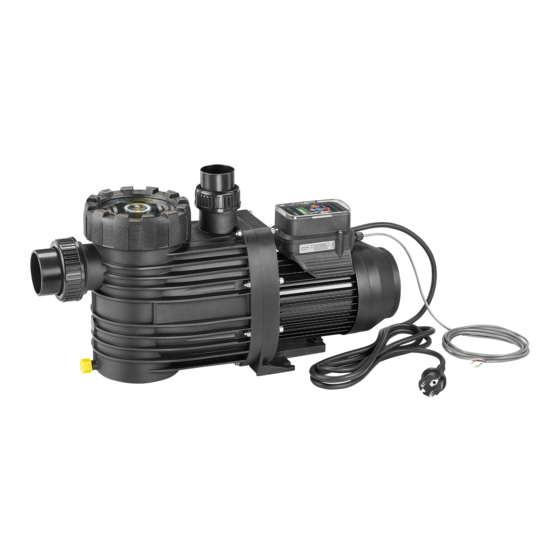
- Page 1 Pumpendatenblatt Data sheet Fiche technique pompe Pompgegevens Documentazione pompa Ficha técnica de la bomba BADU ® Eco Touch-pro Hauptstraße 1-3 91233 Neunkirchen a. Sand Germany Tel. +49 9123-949-0 Fax +49 9123-949-260 info@speck-pumps.com www.speck-pumps.com 04/2014 VG 766.2150.069 2‘ KR/BA...
- Page 2 ~120 D90.04.227 50Hz / 60Hz n=2830 min n=2400 min n=2000 min n=1000 min Q (m KL90.04.234 VG 766.2150.069 04/2014...
- Page 3 Eco Touch-pro ® TD 50/60Hz BADU min. max. 1000 min 2830 min Sa/mm Da/mm d-Saug/mm d-Druck/mm L/mm 1~ 230 V 0,08 1,05 0,03 0,75 0,60 6,50 Lpa (1 m)/dB(A) 49,3 65,8 Lwa/dB(A) m/kg 9,00 ● ● ○ ○ 2,00 15,0 max.
- Page 4 Glossar | Glossary | Glossaire | Woordenlijst | Glossario | Glosario Technische Daten | Technical data | Données techniques | Technische gegevens | Dati tecnici | Datos técnicos Sauganschluss | Inlet connection | Raccordement aspiration | Zuigaansluiting | Raccordo aspirazione | Conexión por aspración Druckanschluss | Outlet connection | Raccordement refoulement | Persaansluiting | Raccordo mandata | Conexión...
- Page 5 Glossar | Glossary | Glossaire | Woordenlijst | Glossario | Glosario Gewicht | Weight | Poids | Gewicht | Peso | Peso Wicklungsschutzkontakt oder Motorschutzschalter | Built-in or external overlaod switch | Disjoncteur thermique intégré dans le bobinage ou disjoncteur protecteur du moteur | Wikkelingsbeschermingscontact of motorbeveiligingsschakelaar | Contatto di terra dell’avvolgimento oppure salvamotore | Protector térmico...
- Page 6 Glossar | Glossary | Glossaire | Woordenlijst | Glossario | Glosario P-GHI 2,5 bar maximaler Gehäuseinnendruck/maximaler Systemdruck | 2,5 bar max. casing pressure/system pressure | 2,5 bar de pression maximale à l‘intérieur du carter/pression maximale de l’équipement | 2,5 bar maximale huisdruk/maximale systeemdruk | 2,5 bar massima pressione interna corpo/massima pressione sistema | 2,5 bar presión interna máxima de carcasa/presión máxima del sistema...
- Page 7 Glossar | Glossary | Glossaire | Woordenlijst | Glossario | Glosario 1~/3~ Geeignet für Dauerbetrieb bei | Suitable for continuous operation at | Adaptée à un fonctionnement ininterrompu à | Geschikt voor continu gebruik bij | Adatta per funzionamento continuo a | Apropiado para un servicio continuo a 1~ 220 - 240 V ±...
- Page 8 Die Pumpe besitzt einen Permanentmagnet-Motor und ist elektronisch vor Überlas- tung gesichert. Anschluss externer Schaltkontakte Zur externen Ansteuerung besitzt die Pumpe ein 5-adriges Kabel mit offenen Enden. Zuordnung der Kabel zu den einzelnen Drehzahlen wie folgt: Weiß = n 3 Grün = n 2 Braun...
- Page 9 Voreinstellung: Geschwindigkeit: 3 = 2830 min 2 = 2400 min 1 = 2000 min Ansauggeschwindigkeit: = 2830 min Ansaugzeit: = 5 Minuten einstellbare Geschwindigkeiten: 1000 - 2830 min (in 50 min Schritten) einstellbare Ansaugzeit: 0 - 10 Min. (in 1 Min. Schritten) Bedienoberfläche: ...
- Page 10 gestoppt. Die "Power"-LED blinkt und das Display zeigt "OFF" an. Hinweis: Bei der Verwendung der BADU Eco Touch-pro mit einer externen Steuerung, muss beim Programmieren der Drehzahlen und der Ansaugzeit die Verbindung zu der externen Steuerung unterbrochen oder diese von der Netzspannung getrennt werden! Einstellen der Festdrehzahlen Die Taste der Festdrehzahl, die verändert...
- Page 11 Einstellen der Ansaugparameter Zum Programmieren der Ansaugzeit muss der Motor gestoppt werden (Taste "0"). Dann wieder die "SET"-Taste für min. 3 Sekunden drücken, bis die Drehzahlanzeige im Display anfängt zu blinken. Nun kann die Drehzahl eingestellt werden, mit der der Motor während der Ansaugzeit fahren soll.
- Page 12 Das Display der Steuerung schaltet sich nach drei Minuten ohne Aktion ab, außer eine externe Steuerung gibt z. B. jede Minute ein Signal an die Pumpe. Die Pumpe läuft nach einem Spannungsverlust automatisch wieder mit der zuletzt eingestellten Drehzahl an oder bleibt stehen, wenn sie zuvor gestoppt wurde. 12 DE VG 766.2150.069 04/2014...
- Page 13 Übersicht möglicher Betriebs- und Fehlermeldungen Ist ein Fehler aufgetreten, schaltet der Motor dauerhaft ab. Ausnahmefehler: „Unterspannung“. Hier schaltet der Motor wieder selbsttätig ein, sofern die Spannung für mindestens 6 Sekunden über 209 V liegt. Tritt ein Fehler auf, so ist die Anlage von der Spannungsversorgung zu trennen. Siehe Kapitel 2.2 der Originalbetriebsanleitung „Normal und selbstansaugende Pumpen mit/ohne Kunststofflaternen-Ausführung (AK)“.
-
Page 14: Deckel/Saugsieb Demontieren Bzw. Montieren
Mitgeltende Dokumente Zu diesem Pumpendatenblatt gehört die Originalbetriebsanleitung "Normal und selbstansaugende Pumpen mit/ohne Kunststofflaternen-Ausführung (AK)". Sie muss für das Bedien- und Wartungspersonal frei zugänglich sein. Deckel/Saugsieb demontieren bzw. montieren W72.40.007-1 14 DE VG 766.2150.069 04/2014... - Page 15 The pump has a permanently magnetic motor and is electronically protected against overload. Connecting external switch contacts The pump has a 5-wire cable with open ends for external control. Assignment of the cables to the individual speeds is as follows: White = n 3 Green...
- Page 16 Default setting: Speed: 3 = 2830 min 2 = 2400 min 1 = 2000 min Priming speed: = 2830 min Priming time: = 5 minutes Speeds which can be set: 1000 - 2830 min (in 50 min steps) Priming time which can be set: 0 - 10 minutes (in 1 minute steps) User interface: ...
- Page 17 "0". The "Power" LED flashes and the display shows "OFF". Note: When the BADU Eco Touch-pro is used with an external control, the connection to the external control has to be interrupted or the external control has to be disconnected from the mains voltage when programming...
- Page 18 Setting the priming parameters The motor has to be stopped ("0" button) to programme the priming time. Then press the "SET" button again for at least 3 seconds until the speed displayed in the display begins to flash. Now the speed can be set with which the motor is to start up during the priming time.
- Page 19 The display of the control unit switches off after 3 minutes without action, except if an external control unit for example emits a signal to the pump every minute. After a voltage drop the pump automatically starts up again with the speed last set, or remains stopped if it had been stopped beforehand.
- Page 20 Overview of possible operating and error messages If an error occurs, the motor switches off permanently. Exception error: "Undervoltage". The motor automatically switches back on as soon as the voltage lies over 209 V for at least 6 seconds. If an error occurs, the system must be disconnected from the power supply. See Chapter 2.2 of the original Operating Manual "Non self-priming and self-priming pumps with/without plastic lanterns (AK version)".
-
Page 21: Related Documentation
Related Documentation The additional information compiled in this data sheet must be kept together with the original Operating Manual for "Non self-priming and self-priming pumps with/without plastic lanterns (AK version)" and must be accessible to the relevant personnel at all times. - Page 22 La pompe possède un moteur à entraînement électro magnétique avec protection contre la surcharge. Raccordement de contacts de commutation externes Pour la commande externe, la pompe possède un câble à 5 fils aux extrémités libres. L'affectation des fils du câble aux différentes vitesses de rotation est la suivante: Blanc = n 3 Vert...
- Page 23 Préréglage: Vitesse: 3 = 2830 min 2 = 2400 min 1 = 2000 min Vitesse d'aspiration: = 2830 min Temps d'aspiration: = 5 minutes Vitesses réglables: 1000 - 2830 min (par intervalles de 50 min Temps d'aspiration réglable: 0 - 10 min (pas intervalles d’une min.) Interface de commande: ...
- Page 24 La LED "Power" clignote et l'écran affiche "OFF". Indication: En cas d'utilisation de la BADU Eco Touch-pro avec une commande externe, pendant la programmation des vitesses de rotation et du temps d'aspiration, la liaison à la commande externe doit être interrompue ou séparée de la tension de réseau!
- Page 25 Réglage des paramètres d'aspiration Pour la programmation du temps d'aspiration, le moteur doit être coupé (touche "0"). Ensuite, appuyer à nouveau pendant au moins 3 seconds sur la touche "SET", jusqu'à ce que l'affichage de vitesse de rotation à l’écran commence à...
- Page 26 L'écran de la commande s'éteint après trois minutes sans activité, sauf si une commande externe donne p. ex. à chaque minute un signal à la pompe. Après une coupure de tension, la pompe tourne automatiquement à nouveau avec la vitesse de rotation réglée en dernier lieu ou demeure à...
- Page 27 Vue d'ensemble des messages de fonctionnement et de défaut possibles En cas de défaut, le moteur se met durablement hors service. Exception: "Sous- tension". Dans ce cas, le moteur se remet automatiquement en service pour autant que la tension soit supérieure à 209 V pendant au moins 6 s. En cas de défaut, l'installation doit être isolée de l'alimentation électrique.
-
Page 28: Documents Applicables
Documents applicables Le présent document fait partie intégrante de la notice d’utilisation originale pour pompes non auto-amorçantes ou auto-amorçantes avec/sans lanterne plastique (exécution AK). Il est recommandé de le tenir accessible aux personnes chargées de l’utilisation et de la maintenance. Monter/démonter le couvercle/le panier filtrant W72.40.007-1 28 FR... - Page 29 De pomp is voorzien van een motor met permanente magneet en is elektronisch beveiligd tegen overbelasting. Aansluiting van externe schakelcontacten Voor externe aansturing is de pomp voorzien van een 5-aderige kabel met open uiteinden. De aders van de kabel zijn als volgt toegewezen aan de betreffende toerentallen: = n 3 Groen...
- Page 30 Standaardinstelling: Snelheid: 3 = 2830 min 2 = 2400 min 1 = 2000 min Aanzuigsnelheid: = 2830 min Aanzuigtijd: = 5 minuten Instelbare snelheden: 1000 - 2830 min (in stappen van 50 min Instelbare aanzuigtijd: 0 - 10 min. (in stappen van 1 min.) Bedieningsinterface: ...
- Page 31 "Power"-LED knippert en het display toont de tekst "OFF". Aanwijzing: Bij gebruik van de BADU Eco Touch-pro met externe besturing moet bij het programmeren van de toerentallen en de aanzuigtijd de verbinding met de externe besturing worden onderbroken of moet deze...
- Page 32 Instellen van de aanzuigparameters Om de aanzuigtijd te programmeren moet de motor worden gestopt (toets "0"). Druk vervolgens weer gedurende ten minste 3 sec. op de "SET"-toets tot de toerentalweergave op het display begint te knipperen. Nu kan het toerental worden ingesteld waarmee de motor gedurende de aanzuigtijd moet lopen.
- Page 33 Het display van de besturing schakelt uit wanneer er gedurende drie minuten niet op een toets is gedrukt, tenzij een externe besturing b.v. elke minuut een signaal naar de pomp stuurt. De pomp loopt na een stroomstoring automatisch weer aan met het laatst ingestelde toerental of blijft stilstaan wanneer deze daarvoor was gestopt.
- Page 34 Overzicht van mogelijke bedrijfs- en storingsmeldingen Wanneer een storing is opgetreden, schakelt de motor permanent uit. Een uitzondering hierop is de storing: "Onderspanning". Hierna schakelt de motor weer vanzelf in zodra de spanning gedurende ten minste 6 sec. meer dan 209 V bedraagt. Wanneer een storing is opgetreden, moet de installatie worden losgekoppeld van de voeding.
-
Page 35: Deksel/Filtermandje Demonteren Respectievelijk Monteren
Relevante documenten Bij dit pompdatablad hoort de originele gebruiksaanwijzing "Normaal en zelfaanzuigende pompen met/zonder kunststof lantaarn (AK)". Deze moet voor het bedienings- en onderhoudspersoneel te allen tijde beschikbaar zijn. Deksel/filtermandje demonteren respectievelijk monteren W72.40.007-1 04/2014 VG 766.2150.069 NL 35... - Page 36 La pompa possiede un motore a magneti permanenti ed è protetta elettronicamente dal sovraccarico. Collegamento di contatti di commutazione esterni Per il comando esterno, la pompa possiede un cavo a 5 conduttori con estremità aperte. I conduttori del cavo sono associati ai seguenti numeri di giri: Blanco = n 3 Verde...
- Page 37 Impostazione predefinita: Velocità: 3 = 2830 min 2 = 2400 min 1 = 2000 min Velocità in modalità di aspirazione: = 2830 min Tempo di aspirazione: = 5 minuti Velocità regolabili: 1000 - 2830 min (ad incrementi di 50 min Tempo di aspirazione regolabile: 0 - 10 min (ad incrementi di 1 min) ...
- Page 38 LED "Power" lampeggia ed il display visualizza "OFF". Avviso: Utilizzando il BADU Eco Touch-pro con una centralina di comando esterna, prima di programmare il numero di giri ed il tempo di aspirazione è necessario interrompere il collegamento con la centralina di comando esterna o staccare quest'ultima dalla tensione elettrica! ...
- Page 39 Impostazione dei parametri di aspirazione Per programmare il tempo di aspirazione è necessario arrestare il motore (tasto "0"). Poi ripremere il tasto "SET"per almeno 3 secondi finché l'indicazione del numero di giri sul display non inizia a lampeggiare. Ora si può impostare il numero di giri con cui il motore deve funzionare durante il tempo di aspirazione.
- Page 40 Dopo tre minuti senza alcuna azione, il display della centralina di comando si spegne se una centralina di comando esterna non invia un segnale alla pompa, ad esempio ogni minuto. In seguito ad una caduta di tensione la pompa si riavvia automaticamente con l'ultimo numero di giri impostato o resta ferma se prima era stata arrestata.
- Page 41 Prospetto dei possibili messaggi di errore e di servizio In seguito al verificarsi di un errore, il motore si spegne permanentemente. Eccezione: "sottotensione". In questo caso il motore si riaccende automaticamente se la tensione resta maggiore di 209 V per almeno 6 secondi. Se si verifica un errore, l'impianto deve essere scollegato dalla tensione di alimentazione.
-
Page 42: Altri Documenti Applicabili
Altri documenti applicabili Le istruzioni di funzionamento originali "Pompe aspirazione normale e autoadescanti, con e senza campana – esecuzione (AK)" fanno parte a questa documentazione pompa. Queste devono essere ben accessibili per il personale di servizio e per il personale di assistenza. Smontaggio e montaggio del coperchio/cestello W72.40.007-1 42 IT... - Page 43 La bomba tiene un motor de imán permanente y está protegida electrónicamente contra sobrecarga. Conexión de contactos de conmutación externos Para el mando externo la bomba tiene un cable de 5 hilos con cabos abiertos. Asignación de los cables a las velocidades de giro individuales de la siguiente manera: Blanco = n 3...
- Page 44 Ajuste previo: Velocidad: 3 = 2830 min 2 = 2400 min 1 = 2000 min Velocidad de aspiración: = 2830 min Tiempo de aspiración: = 5 minutos Velocidades ajustables: 1000 - 2830 min (en pasos de 50 min Tiempo de aspiración ajustable: 0 - 10 min.
- Page 45 LED "Power" parpadea y el display indica "OFF". Nota: ¡Cuando se utiliza el BADU Eco Touch-pro con un mando externo, al programar las velocidades de giro y el tiempo de aspiración se debe interrumpir la conexión al mando externo, o aislarlos de la tensión de red! ...
- Page 46 Ajuste de los parámetros de aspiración Para programar el tiempo de aspiración debe estar parado el motor (tecla "0"). Luego pulsar otra vez la tecla "SET" durante mín. 3 segundos, hasta que la indicación de velocidad de giro en el display comienza a parpadear. Ahora puede ajustarse la velocidad de giro con la que el motor funcionará...
- Page 47 El display del mando se apaga después de tres minutos sin acción, excepto un mando externo envía p.ej. cada minuto una señal a la bomba. La bomba arranca automáticamente después de un corte de corriente de nuevo con la velocidad de giro últimamente ajustada, o permanece parada si antes se detuvo.
- Page 48 Presentación de posibles avisos de funcionamiento y mensajes de error Si se produjo un fallo, el motor se desconecta de forma permanente. Fallo excepcional: "Tensión insuficiente". En este caso, el motor se conecta automáticamente de nuevo cuando la tensión sobrepasa 209 V durante al menos 6 segundos.
-
Page 49: Documentos Incluidos
Documentos incluidos En esta hoja de datos de la bomba se incluyen las instrucciones originales para bombas de "Aspiración normal y bombas auto-aspirantes con/sin la versión (AK)". Usted debe facilitar el libre acceso para el personal de operación y mantenimiento. Tapa/montaje o desmontaje de los prefiltros de aspiración W72.40.007-1... - Page 50 VG 766.2150.069 04/2014...
- Page 51 04/2014 VG 766.2150.069...
-
Page 52: Eg-Konformitätserklärung
Geschäftsführer | Managing Director | Directeur technique | Technisch directeur | Gérant | Bedrijfsleider | Amministratore | Direttotore tecnico | Director técnico Gerente 91233 Neunkirchen a. Sand, 01.04.2014 Speck Pumpen Verkaufsgesellschaft GmbH Hauptstraße 1-3, 91233 Neunkirchen a. Sand VG 766.2150.069 04/2014... - Page 53 Normal- und selbstansaugende Pumpen mit/ohne Kunststofflaternen-Ausführung (AK) Non self-priming and self-priming pumps with/without plastic lantern construction (AK) Pompes non auto-amorçantes ou auto-amorçantes avec/sans lanterne plastique (exécution AK) Normaal en zelfaanzuigende pompen met/zonder uitvoering met kunststof lantaarn Pompe aspirazione normale e autoadescanti con/senza campana in plastica (AK) Bombas normales y auto-aspirantescon/sin linternas de plástico-diseño (AK)
- Page 54 Inhaltsverzeichnis Inhaltsverzeichnis DE Originalbetriebsanleitung für ........ 3 EN Original operation manual for ......27 FR Instruction d'utilisation originale pour ....51 NL Oorspronkelijke gebruikershandleiding voor ..77 IT Manuale d'istruzioni originale per ..... 102 ES Instrucciones para el manejo originales para .. 126 2 DE│EN│FR│NL│IT│ES VG 766.2000.055 06/2014...
- Page 55 Originalbetriebsanleitung für Normal- und selbstansaugende Pumpen mit/ohne Kunststofflaternen- Ausführung (AK) Hauptstraße 1-3 91233 Neunkirchen a. Sand Germany Tel. +49 9123-949-0 Fax +49 9123-949-260 info@speck-pumps.com www.speck-pumps.com 06/2014 VG 766.2000.055 75’ KR/BA...
-
Page 56: Table Des Matières
Inhaltsverzeichnis Inhaltsverzeichnis Zu diesem Dokument ..............6 Umgang mit dieser Anleitung ........... 6 Mitgeltende Dokumente ............6 1.2.1 Symbole und Darstellungsmittel ........6 Sicherheit ..................8 Bestimmungsgemäße Verwendung ......... 8 ... - Page 57 Salzkristalle bei Kunststofflaternen-Ausführung (AK) entfernen ................26 Alle Rechte vorbehalten. Inhalte dürfen ohne schriftliche Zustimmung von Speck Pumpen Verkaufsgesellschaft GmbH weder verbreitet, vervielfältigt, bearbeitet noch an Dritte weitergegeben werden. Dieses Dokument sowie alle Dokumente im Anhang unterliegen keinem Änderungsdienst! Technische Änderungen vorbehalten!
-
Page 58: Zu Diesem Dokument
1 Zu diesem Dokument Zu diesem Dokument Umgang mit dieser Anleitung Diese Anleitung ist Teil der Pumpe. Die Pumpe wurde nach den anerkannten Regeln der Technik hergestellt und geprüft. Dennoch können bei unsachgemäßer Verwendung, bei unzureichender Wartung oder unzulässigen Eingriffen Gefahren für Leib und Leben bzw. materielle Schäden entstehen. - Page 59 1 Zu diesem Dokument Um die korrekte Bedienung zu verdeutlichen, sind wichtige Informationen und technische Hinweise besonders herausgestellt. Symbol Bedeutung Einschrittige Handlungsaufforderung. Mehrschrittige Handlungsanleitung. Reihenfolge der Schritte beachten. 06/2014 VG 766.2000.055 DE 7...
-
Page 60: Sicherheit
2 Sicherheit Sicherheit Bestimmungsgemäße Verwendung Die Pumpe ist zur Umwälzung von Schwimmbadwasser in Verbindung mit einer Schwimmbad-Filteranlage vorgesehen. Ausnahmen siehe Pumpendatenblatt. Zur bestimmungsgemäßen Verwendung gehört die Beachtung folgender Informationen: Diese Anleitung. Pumpendatenblatt. Die Pumpe darf nur innerhalb der Einsatzgrenzen und Kennlinien betrieben werden, die im Pumpendatenblatt festgelegt sind. -
Page 61: Sicherheitsvorschriften
2 Sicherheit – Das Personal, das die entsprechende Qualifikation noch nicht aufweisen kann, erhält die erforderliche Schulung, bevor es mit anlagentypischen Aufgaben betraut wird. – Die Zuständigkeiten des Personals, z. B. für Arbeiten am Produkt, an der elektrischen Ausrüstung oder den hydraulischen Einrichtungen, sind entsprechend seiner Qualifikation und Arbeitsplatzbeschreibung festgelegt. -
Page 62: Restrisiken
2 Sicherheit Restrisiken 2.7.1 Herabfallende Teile Die Tragösen am Motor sind nur für das Gewicht des Motors ausgelegt. Beim Anhängen eines kompletten Pumpenaggregats können die Trag- ösen ausbrechen. Pumpenaggregat, bestehend aus Motor und Pumpe, sowohl motor- als auch pumpenseitig anhängen. Nur geeignete und technisch einwandfreie Hebezeuge und Lastaufnahmemittel verwenden. -
Page 63: Heiße Oberflächen
2 Sicherheit Schwimmbecken und deren Schutzbereiche gemäß DIN VDE 0100- 702 errichten. Vor Arbeiten an der elektrischen Anlage folgende Maßnahmen ergreifen: – Anlage von der Spannungsversorgung trennen. – Warnschild anbringen: „Nicht einschalten! An der Anlage wird gearbeitet." – Spannungsfreiheit prüfen. Elektrische Anlage regelmäßig auf ordnungsgemäßen Zustand prüfen. -
Page 64: Vermeidung Von Sachschäden
2 Sicherheit Vermeidung von Sachschäden 2.9.1 Undichtigkeit und Rohrleitungsbruch Schwingungen und Wärmeausdehnung können Rohrleitungsbrüche verursachen. Pumpe so installieren, dass Körper- und Luftschallübertragung reduziert werden. Dabei die einschlägigen Vorschriften beachten. Durch Überschreitung der Rohrleitungskräfte können undichte Stellen an den Flanschverbindungen oder an der Pumpe selbst entstehen. Pumpe nicht als Festpunkt für die Rohrleitung verwenden. -
Page 65: Druckstöße
2 Sicherheit 2.9.5 Druckstöße Schlagartig schließende Armaturen können Druckstöße verursachen, die den maximal zulässigen Gehäusedruck der Pumpe mehrfach übersteigen. Druckstoßdämpfer oder Windkessel einbauen. 2.9.6 Blockieren der Pumpe Schmutzteilchen in der Saugleitung können die Pumpe verstopfen und blockieren. Pumpe nicht ohne Saugsieb bzw. Saugsiebgriff in Betrieb nehmen. Pumpe vor Inbetriebnahme und längerer Stillstands- oder Lagerzeit auf Leichtgängigkeit prüfen. -
Page 66: Beschreibung
3 Beschreibung Beschreibung Komponenten W90.04.086-1 A Normalsaugende Pumpe B Selbstansaugende Pumpe (1) Saugstutzen (3) Motor (2) Druckstutzen (4) Deckel mit Saugsieb Funktion Die Pumpe saugt das Wasser aus dem Schwimmbecken über eine Absperrarmatur und den Saugstutzen (1) an. Das Saugsieb (4), falls vorhanden, filtert grobe Verschmutzungen aus. -
Page 67: Transport Und Zwischenlagerung
4 Transport und Zwischenlagerung Transport und Zwischenlagerung Korrosion durch Lagerung in feuchter Luft bei wechselnden Temperaturen! Kondenswasser kann Wicklungen und Metallteile angreifen. Pumpe in trockener Umgebung bei möglichst konstanter Temperatur zwischenlagern. Beschädigung des Gewindes und Eindringen von Fremdkörpern durch ungeschützte Stutzen! Stutzenabdeckungen erst vor Anschließen der Rohrleitungen entfernen. -
Page 68: Installation
5 Installation Installation Einbauort 5.1.1 Aufstellen im Freien Um die Lebensdauer der Pumpe zu erhöhen, einen einfachen Regenschutz vorsehen. 5.1.2 Bodenablauf muss vorhanden sein Größe des Bodenablaufs nach folgenden Kriterien bemessen: – Größe des Schwimmbeckens. – Umwälzvolumenstrom. 5.1.3 Be- und Entlüftung Für ausreichende Be- und Entlüftung sorgen. -
Page 69: Rohrleitungen
5 Installation Rohrleitungen 5.2.1 Rohrleitung dimensionieren Zu lange Saugleitungen haben erhebliche Nachteile: Höherer Widerstand, dadurch schlechteres Ansaugverhalten und höhere Kavitationsgefahr. Längere Ansaugzeit, bis zu 12 min. Die Rohrleitungsdimensionen, die im Pumpendatenblatt spezifiziert sind, gelten nur für eine Leitungslänge von max. 5 m. Bei längeren Rohrleitungen sind die Rohrreibungsverluste zu berücksichtigen. -
Page 70: Aufstellung
5 Installation Hinweis: Bei einer undichten Saugleitung saugt die Pumpe schlecht oder überhaupt nicht. Dichtigkeit der Saugleitung sicherstellen und gewährleisten, dass der Deckel fest aufgeschraubt ist. Aufstellung Die Pumpe kann entweder unterhalb im Zulaufbetrieb oder oberhalb im Saugbetrieb des Wasserniveaus aufgestellt werden. W90.80.020 A Aufstellung oberhalb B Aufstellung unterhalb... -
Page 71: Elektrischer Anschluss
5 Installation Beschädigung des Motors durch unzureichenden Leckageabfluss! Leckageabfluss zwischen Pumpengehäuse und Motor nicht verstopfen oder abdichten. Durch unsachgemäße Abdichtung können Gewinde beschädigt und die Dichtwirkung beeinträchtigt werden! Je nach Pumpentyp werden Teflonband oder die beiliegende Verschraubung zur Montage der Rohrleitung verwendet. Bei ABS-Verklebungen muss eine Aushärtezeit von mindestens 12 Stunden berücksichtigt werden. - Page 72 5 Installation WARNUNG! Stromschlaggefahr durch Spannung am Gehäuse! Bei Pumpen mit Drehstrom- oder mit Wechselstrommotor ohne Motorschutz, siehe Pumpendatenblatt, muss ein korrekt eingestellter Motorschutzschalter installiert werden. Dabei Werte auf dem Typenschild beachten. Stromkreis mit einem Fehlerstromschutzschalter, Nennfehlerstrom ≤ 30 mA, schützen. Δ...
-
Page 73: Inbetriebnahme
6 Inbetriebnahme Inbetriebnahme Beschädigung der Pumpe durch Trockenlauf! Sicherstellen, dass Pumpe immer mit Wasser gefüllt ist. Dies gilt auch für die Drehrichtungskontrolle. Selbstansaugende Pumpe mit Wasser füllen 1. Deckel abnehmen, siehe Kapitel 8.1, Seite 25. Hochkonzentrierte Wasserpflegemittel können die Pumpe beschädigen! Keine Wasserpflegemittel, insbesondere in Tablettenform, in das Saugsieb legen. - Page 74 6 Inbetriebnahme Beschädigung der Pumpe durch Trockenlauf! Pumpe und Saugleitung entlüften. 3. Pumpe einschalten. Wenn die Pumpe einen Drehstrommotor hat und dieser sich in die falsche Richtung dreht, ist die Pumpe lauter und fördert weniger. 4. Bei Drehstrommotor: Darauf achten, dass sich der Motor in Richtung des aufgeklebten Pfeils dreht.
-
Page 75: Störungen
7 Störungen Störungen Es ist normal, dass von Zeit zu Zeit einige Tropfen Wasser durch die Gleitringdichtung austreten. Das gilt insbesondere während der Einlaufzeit. Je nach Wasserbeschaffenheit und Betriebsstundenzahl kann die Gleitringdichtung undicht werden. Bei permanentem Wasseraustritt Gleitringdichtung wechseln. Wir empfehlen, bei Unregelmäßigkeiten zunächst den Schwimmbadbauer zu verständigen. - Page 76 7 Störungen Motorwelle schwergängig: 1. Schraubendreher entfernen. 2. Kundendienst verständigen und Pumpe prüfen lassen. Motorwelle leichtgängig: 1. Schraubendreher entfernen. 2. Druckseitige Armatur nur halb öffnen. 3. Spannungsversorgung wieder herstellen. Wenn die Pumpe festsitzt, kann der Motor durch mehrmaliges Einschalten beschädigt werden. Sicherstellen, dass die Pumpe nur einmal eingeschaltet wird.
-
Page 77: Instandhaltung
8 Instandhaltung Instandhaltung Vor Instandhaltungsarbeiten alle Absperrarmaturen schließen und Leitungen entleeren. Alle Pumpen Wann? Was? Regelmäßig Saugsieb reinigen. Bei Frostgefahr Pumpe und frostgefährdete Leitungen rechtzeitig entleeren. Zusätzlich bei Kunststofflaternen-Ausführung (AK) Wann? Was? Regelmäßig Salzkristalle, bedingt durch Salzwasser, entfernen, siehe Kapitel 8.3, Seite 26. Vor längerem Pumpe mit Leitungswasser spülen, um Stillstand... -
Page 78: Salzkristalle Bei Kunststofflaternen-Ausführung (Ak) Entfernen
8 Instandhaltung Hochkonzentrierte Wasserpflegemittel können die Pumpe beschädigen! Keine Wasserpflegemittel, insbesondere in Tablettenform, in das Saugsieb legen. Um ein erneutes Öffnen des Deckels zu erleichtern, den Deckel nur mit Handkraft ohne Öffnungshilfe anziehen. 7. Deckel aufsetzen, siehe Pumpendatenblatt und mit Handkraft anziehen. - Page 79 Original operation manual for Non self-priming and self-priming pumps with/without plastic lantern construction (AK) Hauptstraße 1-3 91233 Neunkirchen a. Sand Germany Tel. +49 9123-949-0 Fax +49 9123-949-260 info@speck-pumps.com www.speck-pumps.com 06/2014 VG 766.2000.055 75’ KR/BA...
- Page 80 Table of contents Table of contents About this document ..............30 Using this manual ..............30 Other applicable documents ..........30 1.2.1 Symbols and means of representation .......30 Safety ..................... 32 ...
- Page 81 (AK version) ................50 All rights reserved. Contents may not be distributed, duplicated, edited or transferred to third parties without the written permission of Speck Pumpen Verkaufsgesellschaft GmbH. This document and all attached documents are not subject to update service.
-
Page 82: About This Document
1 About this document About this document Using this manual This manual is a component of the pump. The pump was manufactured and tested according to the generally accepted rules of technology. However, if the pump is used incorrectly, not serviced enough or tampered with, danger to life and limb or material damage could result. - Page 83 1 About this document To explain correct operation, important information and technical notes are specially marked. Symbol Meaning Instructions for a one-step action. Directions for a multi-step action. Observe the order of the steps. 06/2014 VG 766.2000.055 EN 31...
-
Page 84: Safety
2 Safety Safety Intended use The pump is intended for use to circulate swimming pool water in connection with a swimming pool filter system. See the pump data sheet for exceptions. Observing the following information is vital for intended use: This manual. -
Page 85: Safety Regulations
2 Safety – Personnel which does not yet have suitable qualification must receive the required training before being given jobs typical of the system. – The personnel's responsibilities, e.g. working on the product, electric equipment or hydraulic systems, are set based on qualifications and job description. -
Page 86: Residual Risk
2 Safety Residual risk 2.7.1 Falling parts The lifting hooks on the motor are designed for the weight of the motor. The lifting hooks can break out if the complete pump unit is attached. The pump unit containing the motor and the pump should be attached on both the motor and pump sides. -
Page 87: Hot Surfaces
2 Safety – Attach a warning sign: "Do not switch on! The system is being worked on." – Ensure that the system is free of power. Check the electrical system regularly to ensure it is in proper working condition. 2.7.4 Hot surfaces The electric motor can reach temperatures of up to 70 °C. -
Page 88: Preventing Material Damage
2 Safety Preventing material damage 2.9.1 Leakage and pipe breakage Vibrations and thermal expansion can cause pipe breakage. Install the pump in a manner which reduces structure-borne and airborne noise transmission. When doing so, observe relevant regulations. If the pipe forces are exceeded, leaks can occur at the flange connection or the pump itself. -
Page 89: Pressure Surges
2 Safety 2.9.5 Pressure surges Valves which close suddenly can cause pressure surges which exceed the maximum permissible housing pressure of the pump by far. Install shock absorber or air vessel. 2.9.6 Blockages of the pump Pieces of dirt in the suction line can clog and block the pump. Do not operate a pump without a strainer basket or a strainer basket handle. -
Page 90: Description
3 Description Description Components W90.04.086-1 A Non self-priming pump B Self-priming pump (1) Suction discharge (3) Motor (2) Pressure discharge (4) Lid with strainer basket Function The pump draws the water from the swimming pool via a valve and the suction discharge (1). -
Page 91: Transport And Intermediate Storage
4 Transport and intermediate storage Transport and intermediate storage Corrosion is possible due to being stored in humid air and fluctuating temperatures. Condensation can corrode windings and metal parts. Store the pump in a dry environment at a temperature which is as constant as possible. -
Page 92: Installation
5 Installation Installation Installation site 5.1.1 Outdoor installation In order to increase the pump's service life, provide simple weather protection. 5.1.2 There must be a ground drain Area around the equipment should have appropriate drainage: – Size of the swimming pool. –... -
Page 93: Pipes
5 Installation Pipes 5.2.1 Pipe sizing Suction lines which are too long have significant disadvantages: Higher resistance which results in less efficient priming and a higher risk of cavitation. Longer priming time, up to 12 min. The dimensions which are specified in the pump data sheet apply only to a pipe length of max. -
Page 94: Installation
5 Installation Installation The pump can installed either below the water level with a gravity feed or above it in suction operation. W90.80.020 A Installation above B Installation below water level = suction operation water level = gravity feed (1) Foot valve is necessary for non self-priming pumps In suction feed, the suction height is significantly reduced by flow resistance in the suction line or pipes which are too low or have... -
Page 95: Electrical Connection
5 Installation If it is sealed incorrectly, the thread can be damaged and the sealing effect can be reduced. Depending on the pump type, teflon tape or the quick disconnect unions are used to install the pipe. For ABS bonding, a curing time of at least 12 hours must be observed. The pump can be damaged by strains being placed on the pump! Take up pipe directly before the pump and the pipe should be independently supported. - Page 96 5 Installation Adjust minimum diameter of the pipes, motor output and pipe length. If hazardous situations can occur, provide emergency off switch according to DIN EN 809. The builder/operator must make a decision according to this standard. 44 EN VG 766.2000.055 06/2014...
-
Page 97: Start-Up
6 Start-up Start-up The pump can be damaged if it runs dry. Ensure that the pump is full of water. This also applies to checking the rotation direction. Filling self-priming pump with water 1. Remove lid, see Chapter 8.1, page 49. High concentrations of water treatment chemicals can damage the pump! Do not place water treatment products, particularly in tablet form, for... - Page 98 6 Start-up The pump can be damaged if it runs dry! Purge air from pump and suction line. 3. Switch on the pump. If the pump has a three-phase motor and it turns in the wrong direction, the pump is louder and has a lower capacity. 4.
-
Page 99: Defects
7 Defects Defects It is normal for a few drops of water to escape from the mechanical seal from time to time. This is especially true during the break-in period. Depending on the water quality and number of operating hours, the mechanical seal can begin to leak. - Page 100 7 Defects If the motor shaft is difficult to turn: 1. Remove screwdriver. 2. Notify Customer Service and have the pump tested. If the motor shaft is easy to turn: 1. Remove screwdriver. 2. Only open the valve on the delivery side halfway. 3.
-
Page 101: Maintenance
8 Maintenance Maintenance Before maintenance work, close all valves and drain all pipes. All pumps When? What? Regularly Clean strainer basket If there is a chance Drain pump and pipes sensitive to frost of frost before temperatures drop below freezing. Additionally for pumps with plastic lanterns (AK version) When? What? -
Page 102: Removing Salt Crystals For Pumps With Plastic Lanterns (Ak Version)
8 Maintenance Highly-concentrated water treatment products can damage the pump! Do not place water treatment products, particularly in tablet form, for example chlorine tablets, into the strainer basket. To make it easier to open the lid the next time, tighten the lid by hand only. - Page 103 Instruction d'utilisation originale pour pompes non auto-amorçantes ou auto- amorçantes avec/sans lanterne plastique (exécution AK) Hauptstraße 1-3 91233 Neunkirchen am Sand Germany Tel. +49 9123-949-0 Fax +49 9123-949-260 info@speck-pumps.com www.speck-pumps.com 06/2014 VG 766.2000.055 75’ KR/BA...
- Page 104 Sommaire Sommaire A propos de ce document ............54 Utilisation de ce manuel ............54 Documents applicables ............54 1.2.1 Symboles et représentations graphiques ....54 Sécurité ..................56 Utilisation conforme aux dispositions ........56 ...
- Page 105 Tous droits réservés. Le contenu ne doit pas être distribué, copié, modifié ou encore cédé à un tiers sans l'accord écrit de la société Speck Pumpen Verkaufsgesellschaft GmbH. Ce document ainsi que tous les documents en annexe ne sont aucunement soumis à...
-
Page 106: Propos De Ce Document
1 A propos de ce document A propos de ce document Utilisation de ce manuel Ce manuel d'utilisation fait partie intégrante de la pompe. La pompe à été construite et testée selon les règles de l'art. Toutefois, une utilisation inappropriée, un entretien insuffisant ou une intervention illicite sur le produit peuvent entraîner des dangers de mort ou corporels de l'utilisateur ainsi que des dommages matériels. - Page 107 1 A propos de ce document Symbole Message d'avertis- Signification d'avertis- sement sement ATTENTION Dangers pour les personnes. Le non-respect de ces consignes peut entraîner des blessures légères. – Recommandations permettant d'éviter les dégâts matériels, d'améliorer la compréhension et d'optimiser les méthodes de travail.
-
Page 108: Sécurité
2 Sécurité Sécurité Utilisation conforme aux dispositions La pompe est destinée à la circulation de l'eau des piscines, en association avec un système de filtration de la piscine. Pour les exceptions, vous référer à la fiche technique de la pompe. Le respect des documents suivants permet un fonctionnement conforme aux dispositions : Du présent manuel d'utilisation ;... -
Page 109: Consignes De Sécurité
2 Sécurité – Pour les travaux sur la partie mécanique, comme le changement des roulements à bille ou de la garniture mécanique : mécanicien qualifié. – Pour les travaux sur le système électrique : électricien qualifié. Assurez-vous que les conditions préalables suivantes sont remplies : –... -
Page 110: Changements Structurels Et Pièces De Rechange
2 Sécurité Changements structurels et pièces de rechange Les transformations et modifications peuvent nuire à la sécurité d'exploitation. La pompe ne pourra être modifiée ou transformée qu'après avoir obtenu l'accord du fabricant. Utiliser exclusivement des pièces de rechange originales ou accessoires autorisés par le fabricant. -
Page 111: Énergie Électrique
2 Sécurité – Porter un filet de protection sur les cheveux. – Ne pas porter de bijoux. 2.7.3 Énergie électrique L'environnement humide entraîne un risque élevé d'électrocution lors de la réalisation de travaux sur une installation électrique. Une installation non conforme de la mise à la terre peut également entraîner une électrocution (par exemple, oxydation ou rupture de câble). -
Page 112: Dérangements
2 Sécurité Dérangements En cas d'anomalies constatées, couper et débrancher immédiatement l'installation. Remédier immédiatement à toute sorte d’anomalie. Pompe à l'arrêt Lorsqu’une pompe bloquée est démarrée plusieurs fois de suite, cela peut endommager le moteur. Veuillez respecter les points suivants : Ne pas démarrer la pompe plusieurs fois de suite. -
Page 113: Cavitation
2 Sécurité 2.9.3 Cavitation Des tuyauteries trop longues augmentent la résistance. Il en résulte un risque de cavitation. Assurez-vous que la conduite d'aspiration est étanche. Respecter la longueur maximale des tuyauteries. Mettre en marche la pompe seulement avec la vanne semi ouverte du côté... -
Page 114: Risque De Gel
2 Sécurité 2.9.8 Risque de gel Vidanger en temps voulu la pompe et les tuyauteries présentant un risque de gel. 62 FR VG 766.2000.055 06/2014... -
Page 115: Description
3 Description Description Composants W90.04.086-1 A Pompe non auto amorçante B Pompe auto-amorçante (1) Volute d'aspiration (3) Moteur (2) Tubulure de pression (4) Couvercle avec panier filtrant Fonctionnement La pompe aspire l'eau du bassin par le biais d'un clapet anti-retour et de l’orifice d'aspiration (1). -
Page 116: Transport Et Stockage Intermédiaire
4 Transport et stockage intermédiaire Transport et stockage intermédiaire Corrosion due à un stockage dans un environnement humide et sujet aux variations de température ! La condensation peut endommager le bobinage et les pièces en métal. Stocker la pompe dans un lieu sec et à l'abri des variations de température. -
Page 117: Installation
5 Installation Installation Lieu de montage 5.1.1 Installation en plein air Prévoir une simple protection contre la pluie afin d'augmenter la durée de vie de la pompe. 5.1.2 Une bonde de fond est obligatoire Le diamètre de la bonde de fond est calculé selon les critères suivants : –... -
Page 118: Éléments De Fixation
5 Installation 5.1.6 Éléments de fixation Fixer la pompe avec des vis. Tuyauteries 5.2.1 Dimensions des tuyauteries Des conduites d'aspiration trop longues présentent des inconvénients considérables : Plus forte résistance, d'où une aspiration plus mauvaise et un risque de cavitation plus élevé. Temps d'aspiration plus élevé, jusqu'à... - Page 119 5 Installation Le cas échéant, selon le type de pompe et d'installations, installer un clapet anti-retour. Installer un clapet anti-retour dans la conduite d'aspiration et la conduite de pression. Éviter les robinetteries à fermeture brusque. Le cas échéant, installer des amortisseurs de choc de pression ou des réservoirs d'air.
-
Page 120: Installation
5 Installation Installation La pompe peut être installée soit en dessous (fonctionnement en charge) ou au dessus (fonctionnement en aspiration) du niveau de l'eau. W90.80.020 A Installation au dessus du B Installation en dessous du niveau de l'eau = niveau de l'eau = Fonctionnement en aspiration Fonctionnement en charge (1) Le clapet anti-retour est... -
Page 121: Branchement Électrique
5 Installation Endommagement du moteur suite à un écoulement d'eau insuffisant. L'écoulement d'eau entre le corps de pompe et le moteur ne doit pas être obstrué ou étanchéifié. En cas d'étanchéité incorrecte, les filetages peuvent être endommagés et nuire à l'efficacité de l'étanchéité ! Selon le type de pompe, utiliser une bande de téflon ou les raccords livrés avec la pompe, destinés au montage des tuyauteries. - Page 122 5 Installation AVERTISSEMENT ! Risque de décharge électrique due à la tension dans la pompe ! Pour les pompes avec un moteur à courant alternatif ou à courant continu sans disjoncteur magnéto thermique dans le bobinage (voir la fiche technique de la pompe), installer un dispositif de protection de moteur réglé...
-
Page 123: Mise En Service
6 Mise en service Mise en service Endommagement de la pompe suite à un fonctionnement sans eau ! Assurez-vous que la pompe soit remplie d'eau. Cette recommandation s’applique également au contrôle du sens de rotation. Remplir d'eau la pompe auto-amorçante 1. - Page 124 6 Mise en service 1. Ouvrir complètement la robinetterie côté aspiration. 2. Ouvrir à moitié la robinetterie côté pression. Endommagement de la pompe suit à un fonctionnement sans eau ! Purger la pompe et la conduite d'aspiration. 3. Démarrer la pompe. Si la pompe est équipée d'un moteur à...
-
Page 125: Anomalies
7 Anomalies Anomalies Il est normal que, de temps en temps, des gouttelettes d'eau suintent du joint d'étanchéité. Cela est particulièrement vrai lorsque la pompe est en fonctionnement. Selon la qualité de l'eau et le nombre d'heures de fonctionnement de la pompe, il se peut que le joint d'étanchéité... -
Page 126: Vérifier La Pompe Après Le Déclenchement D'un Contact/Dispositif De Protection
7 Anomalies 7.1.1 Vérifier la pompe après le déclenchement d'un contact/dispositif de protection Si le moteur est coupé par le biais du disjoncteur thermique du bobinage ou du dispositif de protection du moteur, suivez ces étapes : 1. Couper l'alimentation électrique de l'installation. 2. -
Page 127: Maintenance
8 Maintenance Maintenance Fermer tous les clapets anti-retour et vider les tuyauteries avant tous travaux de maintenance. Toutes les pompes Quand ? Quoi ? Régulièrement Nettoyer le panier filtrant. Si risque de gel Vidanger en temps voulu la pompe et les tuyauteries présentant un risque de gel. -
Page 128: Retirer Les Cristaux De Sel D'une Pompe Avec Lanterne Plastique (Ak)
8 Maintenance Les produits d'entretien hautement concentrés peuvent endommager la pompe ! N'introduire aucun produit d'entretien dans le panier filtrant, en particulier sous forme de tablette. Afin de faciliter la réouverture du couvercle, serrer le couvercle uniquement à la main, sans outil de serrage. 7. - Page 129 Oorspronkelijke gebruikershandleiding voor Normaal en zelfaanzuigende pompen met/zonder uitvoering met kunststof lantaarn Hauptstraße 1-3 91233 Neunkirchen a. Sand Germany Tel. +49 9123-949-0 Fax +49 9123-949-260 info@speck-pumps.com www.speck-pumps.com 06/2014 VG 766.2000.055 75‘ KR/BA...
- Page 130 Inhoudsopgave Inhoudsopgave Wat dit document betreft ............. 80 Hoe men met deze handleiding werkt ........80 Documenten die ook relevant zijn .......... 80 1.2.1 Symbolen en weergavemiddelen .......80 Veiligheid ..................82 ...
- Page 131 Zoutkristallen bij uitvoering met kunststof lantaarn (AK) verwijderen ................101 Alle rechten voorbehouden. De inhoud mag, zonder schriftelijke toestemming, van Speck Pumpen Verkaufsgesellschaft GmbH niet verspreid, vermenigvuldigd, bewerkt of aan derden gegeven worden. Dit document en ook alle documenten in de appendix kunnen veranderen.
-
Page 132: Wat Dit Document Betreft
1 Wat dit document betreft Wat dit document betreft Hoe men met deze handleiding werkt Deze handleiding maakt deel uit van de pomp. De pomp is volgens erkende regels van techniek gemaakt en getest. Toch kan bij onoordeelkundig gebruik, ontoereikend onderhoud of ontoelaatbaar gebruik, gevaar voor lichaam en leven, respectievelijk materiële schade ontstaan. - Page 133 1 Wat dit document betreft Om de juiste bediening te verduidelijken worden belangrijke informatie en technische tips hieronder bijzonder benadrukt. Symbool Betekenis Oproep tot handelen in één stap. Handleiding voor handelen in meerdere stappen. Houd de volgorde van de stappen aan. 06/2014 VG 766.2000.055 NL 81...
-
Page 134: Veiligheid
2 Veiligheid Veiligheid Gebruik volgens bestemming De pomp dient ter circulatie van zwembadwater in verbinding met een zwembadfilterinstallatie. Uitzonderingen zie datablad pompgegevens. Bij gebruik volgens bestemming, hoort het volgen van de volgende informatie: Deze handleiding. Datablad pompgegevens. De pomp mag alleen binnen de gebruiksgrenzen en grafieken gebruikt worden die op het datablad beschreven worden. -
Page 135: Veiligheidsvoorschriften
2 Veiligheid Controleren of aan de volgende voorwaarden is voldaan: – Personeel dat nog niet voldoet aan de vereiste kwalificaties moet de juiste scholing volgen, alvorens het te belasten met taken die specifiek voor deze installatie zijn. – De bevoegdheden van het personeel, bijvoorbeeld voor werken aan het product, de elektrische installatie of hydraulische constructies, zijn naar gelang hun kwalificatie en functieomschrijving vastgelegd. -
Page 136: Constructieve Veranderingen En Onderdelen
2 Veiligheid Constructieve veranderingen en onderdelen Ombouw of veranderingen aan de constructie, kan de veiligheid op het werk beïnvloeden. Pomp alleen na afspraak met de fabrikant ombouwen of veranderen. Alleen originele vervangingsonderdelen of toebehoren gebruiken, die door de fabrikant goedgekeurd zijn. Afbeeldingen Alle afbeeldingen op het pompaggregaat in leesbare toestand houden. -
Page 137: Elektrische Energie
2 Veiligheid Bij pompen in de uitvoering met de kunststof lantaarn (AK) kan de draaiende pompas haren, sieraden en kledingstukken vastgrijpen. In de nabijheid van een pomp in bedrijf met een kunststof lantaarn (AK), het volgende in acht nemen: – Nauw sluitende kleding dragen. –... -
Page 138: Aanzuiggevaar
2 Veiligheid 2.7.6 Aanzuiggevaar Er voor zorgen dat aanzuigopeningen voldoen aan de actuele richtlijnen, normen en aanwijzingen. Storingen Bij storingen de installatie meteen stilleggen en uitschakelen. Alle storingen meteen oplossen. Vastzittende pomp Als een vastzittende pomp meerdere malen achter elkaar ingeschakeld wordt, kan de motor beschadigd raken. -
Page 139: Cavitatie
2 Veiligheid 2.9.3 Cavitatie Te lange leidingen verhogen de weerstand. Daardoor bestaat het gevaar van cavitatie. Controleren of de zuigleiding dicht is. De maximale lengte van de leiding in acht nemen. Pomp alleen inschakelen bij half geopende afsluiters aan de perszijde. -
Page 140: Vorstgevaar
2 Veiligheid 2.9.8 Vorstgevaar Pomp en vorstgevoelige leidingen op tijd legen. 88 NL VG 766.2000.055 06/2014... -
Page 141: Beschrijving
3 Beschrijving Beschrijving Componenten W90.04.086-1 A Normaalzuigende pomp B Zelfaanzuigende pomp (1) Zuigaansluiting (3) Motor (2) Persaansluiting (4) Deksel met filtermandje Functie De pomp zuigt het water uit het zwembad aan via een afsluiter en de zuigaansluiting (1). Het filtermandje (4), indien aanwezig, filtert grof vuil eruit. -
Page 142: Transport En Tussenopslag
4 Transport en tussenopslag Transport en tussenopslag Corrosie door opslag in vochtige lucht bij wisselende temperaturen! Condenswater kan wikkelingen en metalen delen beschadigen. Pomp in een droge omgeving bij mogelijk constante temperatuur tussentijds opslaan. Beschadiging van de schroefdraad en het indringen van vreemde voorwerpen door onbeveiligde aansluitingen! Afdekkingen op de aansluitingen pas voor het aansluiten van leidingen verwijderen. -
Page 143: Installatie
5 Installatie Installatie Inbouwplaats 5.1.1 Opstelling in de buitenlucht Om de levensduur van de pomp te verhogen een eenvoudige spatwaterbescherming aanbrengen. 5.1.2 Er moet een bodemvorziening aangebracht zijn Grootte van de bodemafvoer op grond van de volgende criteria meten: – Grootte van het zwembad. –... -
Page 144: Leidingen
5 Installatie Leidingen 5.2.1 De afmetingen van de leidingen bepalen Te lange zuigleidingen hebben aanzienlijke nadelen: Hogere weerstand, daardoor slechtere aanzuigcapaciteit en meer gevaar op cavitatie. Langere aanzuigtijd, tot 12 min. De afmetingen van de leidingen, gespecificeerd in het datablad, gelden alleen voor een leidinglengte van maximaal 5 meter. -
Page 145: Opstelling
5 Installatie Opstelling De pomp kan in toevoerbedrijf of in aanzuigbedrijf t.o.v. het waterniveau opgesteld worden. W90.80.020 A Opstelling boven waterniveau B Opstelling onder waterniveau = aanzuigbedrijf = toevoerbedrijf (1) Voetklep is bij normaalzuigende pompen noodzakelijk Bij aanzuigbedrijf wordt de zuighoogte door stromingsweerstanden in de zuigleiding, te lange leidingen of met een geringe diameter, aanzienlijk verlaagd. -
Page 146: Elektrische Aansluiting
5 Installatie Door een onjuiste afdichting kunnen schroefdraden beschadigd raken en kan de werking van de dichting beïnvloed worden! Naar gelang het pomptype worden teflonband of bijgevoegde schroeven ter montage van leidingen gebruikt. Bij ABS-lijmverbindingen moet een uithardingstijd van minstens 12 uur in acht worden genomen. - Page 147 5 Installatie Alleen geschikte soorten leidingen gebruiken die voldoen aan de regionale voorschriften. Minimale diameter van de leidingen, het motorvermogen en de lengte van de leidingen aanpassen. Als zich gevaarlijke situaties voordoen, brengt u een noodschakelaar volgens DIN EN 809 aan. De gebruiker moet overeenkomstig deze norm handelen.
-
Page 148: Inbedrijfstelling
6 Inbedrijfstelling Inbedrijfstelling Beschadiging van de pomp door droogloop! Controleren of de pomp altijd met water gevuld is. Dit geldt ook voor de controle van de draairichting. Zelfaanzuigende pomp met water vullen 1. Deksel verwijderen, zie hoofdstuk 8.1, bladzijde 100. Hoog geconcentreerde chemicalische middelen voor waterbehandeling kunnen de pomp beschadigen! Geen chemicalische middelen voor waterbehandeling, met name in... - Page 149 6 Inbedrijfstelling Beschadiging van de pomp door droogloop! Pomp en zuigleiding ontluchten. 3. Pomp inschakelen. Als de pomp een draaistroommotor heeft en deze draait in de verkeerde richting, dan maakt de pomp meer geluid en is de capaciteit lager. 4. Bij draaistroommoter: erop letten dat de motor in de richting van de pijl draait (zie sticker).
-
Page 150: Storingen
7 Storingen Storingen Het is normaal dat van tijd tot tijd enkele druppels water door de mechanical seal naar buiten komen. Dat geldt met name tijdens de inlooptijd. Naar gelang de conditie van het water en het aantal bedrijfsuren kan de mechanical seal minder goed afdichten. -
Page 151: Pomp Controleren Na Het Activeren Van Het Wikke- Lingsbeschermingscontact/Beveiligingsschakelaar
7 Storingen 7.1.1 Pomp controleren na het activeren van het wikkelings- beschermingscontact/beveiligingsschakelaar Als de motor door het wikkelingsbeschermingscontact of de motorbeveiligingsschakelaar uitgeschakeld wordt, moet u de volgende stappen doorlopen. 1. De stroomtoevoer van de installatie halen. 2. Motoras aan de kant van de ventilator met een schroevendraaidoordraaien en controleren of deze soepel loopt. -
Page 152: Onderhoud
8 Onderhoud Onderhoud Voor onderhoudswerkzaamheden alle afsluiters sluiten en leidingen legen. Alle pompen Wanneer? Wat? Regelmatig Filtermandje reinigen. Bji vorstgevaar Pomp en vorstgevoelige leidingen op tijd leegmaken. Extra bij uitvoering met kunststof lantaarn (AK) Wanneer? Wat? Regelmatig Zoutkristallen, veroorzaakt door zout water, verwijderen, zie hoofdstuk 8.3, bladzijde 101. -
Page 153: Zoutkristallen Bij Uitvoering Met Kunststof Lantaarn (Ak) Verwijderen
8 Onderhoud Hoog geconcentreerde chemicalische middelen voor waterbehandeling kunnen de pomp beschadigen! Geen chemicalische middelen voor waterbehandeling, met name in tabletvorm, in het filtermandje plaatsen. Om het opnieuw openen van de deksel makkelijker te maken, de deksel alleen aandraaien met handkracht zonder hulpgereedschap. 7. - Page 154 Manuale d'istruzioni originale per pompe aspirazione normale e autoadescanti con/senza campana in plastica (AK) Hauptstraße 1-3 91233 Neunkirchen a. Sand Germany Tel. +49 9123-949-0 Fax +49 9123-949-260 info@speck-pumps.com www.speck-pumps.com 06/2014 VG 766.2000.055 75‘ KR/BA...
- Page 155 1 In relazione a questo documento Indice In relazione a questo documento ..........105 Come gestire queste istruzioni ..........105 Documenti di applicabili ............105 1.2.1 Simboli e mezzi di rappresentazione ......105 ...
- Page 156 Tutti i diritti riservati. I contenuti non potranno essere diffusi, riprodotti, modificati né ceduti a terzi senza il consenso scritto di Speck Pumpen Verkaufsgesellschaft GmbH. Questo documento e tutti i documenti contenuti nell'allegato non sono soggetti ad alcuna revisione!
-
Page 157: In Relazione A Questo Documento
1 In relazione a questo documento In relazione a questo documento Come gestire queste istruzioni Le presenti istruzioni costituiscono parte integrante della pompa. La pompa è costruita e testata secondo gli standard di ingegneria accettati. Tuttavia un utilizzo non conforme, accompagnato da una manutenzione insufficiente o da interventi non autorizzati potrebbe dare origine a situazioni di pericolo e lesioni o danni di natura materiale. - Page 158 1 In relazione a questo documento Per illustrare il corretto utilizzo, sono state appositamente redatte informazioni importanti e avvertenze tecniche. Simbolo Significato - funzione Istruzioni rapide. Istruzioni in più fasi. Rispettare la sequenza delle fasi. 106 IT VG 766.2000.055 06/2014...
-
Page 159: Sicurezza
2 Sicurezza Sicurezza Utilizzo conforme La pompa è stata realizzata per la circolazione dell'acqua delle piscine in collegamento con un gruppo di filtraggio (filtro). Per le eccezioni si veda la scheda tecnica della pompa. Il rispetto delle informazioni riportate di seguito rappresenta un uso conforme: Il presente manuale. -
Page 160: Norme Di Sicurezza
2 Sicurezza – Per gli interventi all'impianto elettrico: elettricista specializzato. Verificare che i seguenti requisiti siano rispettati: – Il personale che non sia in grado di dimostrare il possesso delle necessarie qualifiche, dovrà essere sottoposto a un adeguato corso di formazione prima che gli siano affidate attività tipiche di questo impianto. -
Page 161: Segnali - Etichette
2 Sicurezza Segnali - etichette Tutti i segnali - etichette presenti sul gruppo pompa devono essere chiaramente leggibili. Rischi residui 2.7.1 Caduta di componenti Gli occhielli per il trasporto presenti sul motore sono progettati per il solo peso del motore. Se utilizzati per il gruppo pompa completo, gli occhielli possono rompersi. -
Page 162: Superfici Incandescenti
2 Sicurezza Rispettare le norme VDE e quelle previste dalla società di erogazione dell'energia elettrica. Le piscine e le loro aree di protezione dovranno essere realizzate in conformità con DIN VDE 0100-702 Prima di effettuare lavori sull'impianto elettrico, prendere le seguenti misure precauzionali: –... -
Page 163: Evitare Danni Materiali
2 Sicurezza Ruotare l'albero motore, vedere capitolo 6.2, pagina 120. Pulire la pompa. Evitare danni materiali 2.9.1 Perdite di tenuta e rottura delle tubazioni Oscillazioni ed espansioni termiche possono provocare la rottura delle tubazioni. Installare la pompa in maniera tale da ridurre la propagazione del rumore. -
Page 164: Surriscaldamento
2 Sicurezza 2.9.4 Surriscaldamento I seguenti fattori possono dare luogo a un surriscaldamento della pompa: Pressione eccessiva sul lato pressione. Protezione - salvamotore impostato in maniera non corretta. Temperatura ambiente eccessiva. Non azionare la pompa con valvole chiuse. Per le pompe con motore trifase installare degli interruttori di protezione e impostarli in maniera corretta. -
Page 165: Descrizione
3 Descrizione Descrizione Componenti W90.04.086-1 A Pompa aspirazione normale B Pompa autoadescante (1) Raccordo di aspirazione (3) Motore (2) Raccordo di mandata (4) Coperchio con cestello Funzione La pompa aspira l'acqua dalla piscina passando da una valvola ed arrivando al raccordo di aspirazione (1). Il cestello (4), se presente, filtra lo sporco di dimensioni maggiori. -
Page 166: Trasporto E Immagazzinamento Temporaneo
4 Trasporto e immagazzinamento temporaneo Trasporto e immagazzinamento temporaneo Corrosione provocata dallo stoccaggio in ambiente umido, a temperature variabili! L'acqua di condensa può aggredire gli avvolgimenti e i componenti metallici. Immagazzinare temporaneamente la pompa in un ambiente asciutto, a temperatura quanto più possibile costante. Danneggiamento della filettatura e penetrazione di corpi estranei attraverso bocchettoni - raccordi non protetti! Eliminare le coperture dei bocchettoni - raccordi solo prima di... -
Page 167: Montaggio
5 Montaggio Montaggio Luogo di montaggio 5.1.1 Montaggio all'aperto Per aumentare la durata della pompa, è necessario prevedere un riparo dalla pioggia. 5.1.2 Deve essere presente uno scarico di fondo Le dimensioni dello scarico devono tenere conto dei seguenti criteri: –... -
Page 168: Tubazioni
5 Montaggio Tubazioni 5.2.1 Dimensionamento delle tubazioni Tubi di aspirazione di lunghezza eccessiva presentano significativi svantaggi: Maggiore resistenza e quindi compromessa risposta di aspirazione ed elevato rischio di cavitazione. Tempo di aspirazione prolungato, sino a 12 min. Le dimensioni dei tubi, indicate nella scheda tecnica della pompa, valgono solo per tubi di lunghezza max 5 m. -
Page 169: Montaggio
5 Montaggio Evitare il montaggio di valvole che chiudono a colpi nelle tubazioni. Eventualmente montare degli ammortizzatori di pressione o un polmone compensatore. Avvertenza: In caso di tubazione non a tenuta, la pompa aspirerà in maniera non corretta o non aspirerà affatto. Verificare la tenuta dell’aspirazione e accertarsi che il coperchio sia avvitato in maniera fissa. -
Page 170: Montaggio Della Pompa E Collegamento Alla Tubazione
5 Montaggio In funzionamento aspirazione le portate possono essere ridotte causa lunghezza della tubazione, diametri ridotti e perdite di carico. 5.3.1 Montaggio della pompa e collegamento alla tubazione 1. Montare la pompa orizzontalmente e all’asciutto. Durante tale operazione rispettare le distanze massime rispetto al livello dell'acqua, altezza geodetica. -
Page 171: Collegamento Elettrico
5 Montaggio Collegamento elettrico AVVISO! Un collegamento non corretto comporta il rischio di scariche elettriche! Rispettare le norme VDE ed quelle previste dalla società di erogazione dell'energia elettrica. Le piscine e le loro aree di protezione dovranno essere realizzate in conformità... -
Page 172: Messa In Funzione
6 Messa in funzione Messa in funzione Il funzionamento a secco danneggia la pompa! Assicurarsi che la pompa sia sempre riempita di acqua. Ciò vale anche per i controlli del verso di rotazione. Riempire con acqua la pompa autoadescante 1. Togliere il coperchio, vedere capitolo 8.1, pagina 124. - Page 173 6 Messa in funzione Il funzionamento a secco danneggia la pompa! Sfiatare la pompa e la tubazione di aspirazione. 3. Accendere la pompa. Se la pompa è dotata di un motore trifase e che ruota nella direzione errata, la pompa sarà più rumorosa e avrà una portata minore. 4.
-
Page 174: Guasti - Anomalie
7 Guasti - Anomalie Guasti - Anomalie È normale che occasionalmente si verifichi la fuoriuscita di alcune gocce di acqua dalla tenuta meccanica. Ciò vale in particolare durante la fase di avvio. In funzione delle qualità dell'acqua e del numero di ore di esercizio la tenuta meccanica può... - Page 175 7 Guasti - Anomalie 2. Ruotare l'albero motore sul lato della ventola utilizzando un cacciavite e quindi verificarne la scorrevolezza. L'albero motore si muove con difficoltà: 1. Togliere il cacciavite. 2. Informare il servizio clienti e sottoporre la pompa a ispezione. L'albero motore si muove con facilità: 1.
-
Page 176: Manutenzione
8 Manutenzione Manutenzione Prima di qualsiasi intervento di manutenzione, chiudere tutte le saracinesche e svuotare le tubazioni. Tutte le pompe Quando? Cosa? Regolarmente Pulire il cestello del filtro. In caso di pericolo Svuotare per tempo la pompa e i di gelo componenti esposti al gelo. -
Page 177: Eliminare I Cristalli Sulla Pompa Con Campana In Plastica (Ak)
8 Manutenzione Prodotti di trattamento dell'acqua in concentrazione eccessivamente elevata possono danneggiare la pompa! Non inserire nel cestello prodotti di trattamento dell'acqua, in particolare sotto forma di pastiglie. Per facilitare una successiva apertura del coperchio, limitarsi a fissare il coperchio con le mani, senza usare la chiave a corredo. 7. - Page 178 Instrucciones para el manejo originales para Bombas normales y auto-aspirantes con/sin linternas de plástico-diseño (AK) Hauptstraße 1-3 91233 Neunkirchen a. Sand Germany Tel. +49 9123-949-0 Fax +49 9123-949-260 info@speck-pumps.com www.speck-pumps.com 06/2014 VG 766.2000.055 75‘ KR/BA...
- Page 179 Índice de contenidos Índice de contenidos A este documento............... 129 Manejo de estas instrucciones ..........129 Documentación vigente ............129 1.2.1 Símbolos y tipos de representación ......129 Seguridad ..................131 ...
- Page 180 Retirar los cristales de sal en la versión linternas de plástico (AK) ................ 150 Todos los derechos reservados. Los contenidos sin la autorización escrita de Speck Pumpen Verkaufsgesellschaft GmbH ni difundirse, reproducirse, editarse ni pasarse a terceros. Este documento así como todos los documentos contenidos en el anexo no han de sufrir modificaciones.
-
Page 181: Este Documento
1 A este documento A este documento Manejo de estas instrucciones Estas instrucciones son parte de la bomba. La bomba fue producida y auditada siguiendo la normativa oficial en tecnología No obstante pueden producirse peligros corporales y para la propia vida o daños materiales por un uso indebido, por un mantenimiento inadecuado o una intervención incorrecta. - Page 182 1 A este documento Para explicitar el correcto uso, se han producido informaciones de interés e instrucciones técnicas. Símbolo Significado Solicitud de tratamiento en un paso. Instrucciones de tratamiento en más pasos. Seguir el orden de los pasos. 130 ES VG 766.2000.055 06/2014...
-
Page 183: Seguridad
2 Seguridad Seguridad Uso previsto La bomba se ha previsto para la recirculación del agua del baño en conexión con una instalación de filtros en piscinas. Para excepciones ver ficha técnica de la bomba. Para saber los usos previstos se ha de tener en cuenta la siguiente información: Estas instrucciones. -
Page 184: Cualificación Del Personal
2 Seguridad Cualificación del personal Esta bomba puede ser utilizada por los niños a partir de 8 años y las personas mayores con capacidades físicas, sensoriales o mentales reducidas, o con falta de experiencia y conocimiento si son supervisadas o instruidas acerca del uso seguro de la bomba y que entienden los riesgos resultantes. -
Page 185: Dispositivos De Protección
2 Seguridad Dispositivos de protección Poner las manos en las partes movibles, por ej. en un acoplamiento, puede causar graves daños. Usar la bomba sólo con protección aislante. Modificaciones estructurales y piezas de repuesto Alteraciones o cambios pueden menoscabar la seguridad de uso. Alterar o modificar bombas sólo en consonancia con las instrucciones del productor. -
Page 186: Energía Eléctrica
2 Seguridad En caso de bombas en linternas de plástico-diseño (AK) se pueden quedar restos de pelo, suciedad y trozos de tela en el eje rotatorio de la bomba. Al lado de una bomba en linternas de plástico-diseño en uso tener en cuenta lo siguiente: –... -
Page 187: Material Peligroso
2 Seguridad 2.7.5 Material peligroso Asegurarse, que la evacuación de fugas de eliminación de fluidos peligrosos se hace sin dañar a personas o al medio ambiente. Descontaminar las bombas antes del desmontaje. 2.7.6 Peligro por aspiración Asegurarse que las aperturas de succión se corresponden con las actuales directrices, normas e instrucciones técnicas. -
Page 188: Marcha En Seco
2 Seguridad 2.9.2 Marcha en seco A través de la marcha en seco se pueden dañar sellos mecánicos y las piezas sintéticas en segundos. No dejar secar la bomba mientras está funcionando. Esto también es válido para los controles del sentido de giro. Purgar bombas y tuberías de succión antes de su arranque. -
Page 189: Bloqueo De La Bomba
2 Seguridad 2.9.6 Bloqueo de la bomba Pequeñas partículas en los conductos de aspiración pueden parar y bloquear la bomba. No poner en funcionamiento la bomba sin prefiltros de aspiración o su asa. Comprobar suavidad de movimientos de la bomba, antes de su puesta en marcha y de largos períodos de inactividad o almacenamiento. -
Page 190: Descripción
3 Descripción Descripción Componentes W90.04.086-1 A Bombas con aspiración B Bombas auto-aspirantes normal (1) Boquilla de aspiración (3) Motor (2) Boquilla de impulsión (4) Tapa con prefiltro Función La bomba aspira el agua de las piscinas a través de una cuerpo de la bomba y una boquilla de aspiración. -
Page 191: Transporte Y Almacenamiento Provisional
4 Transporte y almacenamiento provisional Transporte y almacenamiento provisional ¡Corrosión por almacenamiento en zona húmeda por cambio de temperatura! Agua condensada puede afectar al arrollamiento y a las partes metálicas. Almacenar la bomba en ambiente seco y a ser posible a temperatura constante. -
Page 192: Instalación
5 Instalación Instalación Lugar de montaje 5.1.1 Colocación al aire libre Para aumentar la vida útil de la bomba, prever una mera protección en caso de lluvia. 5.1.2 Ha de estar disponible drenaje del suelo Medir el tamaño del drenaje del suelo según los siguientes criterios: –... -
Page 193: Elementos De Fijación
5 Instalación 5.1.6 Elementos de fijación Fijar la bomba con tornillos. Conductos 5.2.1 Dimensionar conductos Conductos demasiado largos tienen cuantiosas desventajas: Alta resistencia, con la que se produce una mala aspiración y hay alto peligro de cavitación. El máximo tiempo de aspiración hasta 12 mín. Las dimensiones de los conductos, las que se especifican en la hoja técnica de como máximo 5 m. -
Page 194: Disposición De Montaje
5 Instalación Evitar repentinos cierres de armadura. Dado el caso montar amortiguadores de brotes de presión o cámaras de aire. Observación: En caso que el conducto no hermético la bomba no aspira bien o en absoluto. Asegurar la densidad de las tuberías de aspiración y garantizar que la cobertura se desatornille de forma consistente. -
Page 195: Montar La Bomba Y Conectar Los Conductos
5 Instalación En caso de funcionamiento de aspiración la altura de aspiración se ha de mantener a través de la resistencia de la corriente en la tubería de succión y conductos lo suficientemente largos o con el suficiente nivel, o sino disminuye el nivel considerablemente. 5.3.1 Montar la bomba y conectar los conductos 1. - Page 196 5 Instalación Instalar separación dispositivo para interrumpir el suministro de energía con mín. 3 mm de apertura de contacto por terminal. ¡CUIDADO! ¡Peligro de electrocución por voltaje en la carcasa! Para bombas con motor trifásico o con corriente alterna sin la protección del motor, consulte la hoja de datos de la bomba, se ha de instalar una conexión de protección del motor correcta.
-
Page 197: Puesta En Marcha
6 Puesta en marcha Puesta en marcha ¡Daño a la bomba por el funcionamiento en seco! Asegúrese de que la bomba está siempre llena de agua. Esto también es válido para los controles del sentido de giro. Llenar con agua bombas auto-aspirantes 1. -
Page 198: Conectar La Bomba
6 Puesta en marcha Conectar la bomba Requisitos: Se ha instalado pantalla de succión, si está disponible. Se monta la cobertura herméticamente. 1. Abrir de forma completa el cuerpo de la bomba de forma completamente abierta. 2. Lado de impresión del cuerpo de la bomba abrir sólo mitad. ¡Daño a la bomba por el funcionamiento en seco! Purgar bomba y tuberías de succión. -
Page 199: Fallos
7 Fallos Fallos Es normal que alguna vez emerjan unas cuantas gotas de agua a través del sello. Esto es especialmente en la fase del tiempo de ejecución. La fuga se ha sellar dependiendo de las condiciones del agua y las horas de funcionamiento. -
Page 200: Comprobar, Después De La Activación De La Bomba, El Control Protección De Contactos/Control Automático
7 Fallos 7.1.1 Comprobar, después de la activación de la bomba, el control protección de contactos/control automático Se desactiva el motor a través del contacto de protección del arrollamiento o la conexión de protección del motor, realice los siguientes pasos: 1. -
Page 201: Mantenimiento
8 Mantenimiento Mantenimiento Antes de cualquier trabajo de mantenimiento cerrar cuerpo de la bomba y vaciar conductos. Todas las bombas ¿Cuándo? ¿Qué? Regularmente Limpie el filtro. Para evitar la Vaciar a tiempo la bomba y los conductos congelación, dañados por el hielo. Además en caso de de la versión linternas plástico (AK) ¿Cuándo? ¿Qué? -
Page 202: Retirar Los Cristales De Sal En La Versión Linternas De Plástico (Ak)
8 Mantenimiento ¡Productos químicos altamente concentrados de tratamiento de agua pueden dañar la bomba! No colocar productos químicos de alta concentración de tratamiento de agua puede dañar la bomba! Para facilitar la re-apertura de la tapa, apriete la tapa con la mano sin ayuda adicional. - Page 203 06/2014 VG 766.2000.055...
- Page 204 VG 766.2000.055 75’ KR/BA 06/2014...