Table des Matières
Publicité
Les langues disponibles
Les langues disponibles
Liens rapides
Grazie per la fiducia accordata e buon divertimento. Con questo
libretto abbiamo voluto darLe le informazioni necessarie per un
corretto uso e una buona manutenzione della Sua moto.
I dati e le caratteristiche indicate sul presente manuale non impegnano la
BETAMOTOR S.p.A che si riserva il diritto di apportare modifiche e miglio-
ramenti ai propri modelli in qualsiasi momento e senza preavviso.
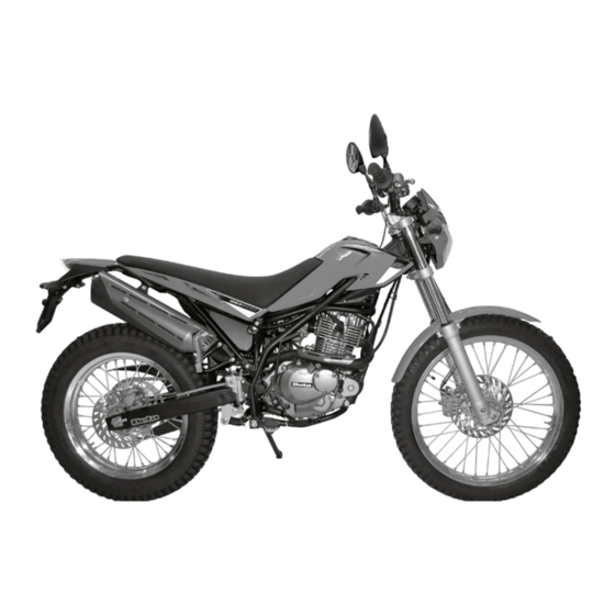
ALP 200
Cod. 017.44.011.00.00
1
I
Publicité
Chapitres
Table des Matières

Manuels Connexes pour Beta Motorcycles ALP 200 2020


Sommaire des Matières pour Beta Motorcycles ALP 200 2020
- Page 1 ALP 200 Grazie per la fiducia accordata e buon divertimento. Con questo libretto abbiamo voluto darLe le informazioni necessarie per un corretto uso e una buona manutenzione della Sua moto. I dati e le caratteristiche indicate sul presente manuale non impegnano la BETAMOTOR S.p.A che si riserva il diritto di apportare modifiche e miglio- ramenti ai propri modelli in qualsiasi momento e senza preavviso.
- Page 2 AVVERTENZA Si raccomanda, dopo la prima o seconda ora di utilizzo in fuori- strada, di controllare tutti i serraggi con particolare attenzione a: • corona • verificare corretto fissaggio pedane • leve/pinze/disco freno anteriore/posteriore • verificare corretto serraggio plastiche • bulloneria motore •...
-
Page 3: Table Des Matières
INDICE DEI CAPITOLI Avvertenze sull’uso del veicolo ..............5 Simbologie .................... 5 Guida sicura ..................6 CAP. 1 INFORMAZIONI GENERALI ........... 7 Dati identificazione veicolo ..............8 Conoscenza del veicolo ................9 Dati tecnici ..................10 Motore ....................12 Impianto elettrico ................. 14 Lampade ..................... - Page 4 Candela ..................... 42 Carburatore ..................42 Freno anteriore ................... 43 Freno posteriore ................... 45 Controllo e regolazione gioco sterzo ............47 Ruota anteriore ..................48 Forcella ....................49 Leveraggio sospensione posteriore ............49 Pneumatici ..................50 Catena ....................51 Faro anteriore ..................52 Sostituzione lampade anteriori ...............
-
Page 5: Avvertenze Sull'uso Del Veicolo
AVVERTENZE SULL’USO DEL VEICOLO • Il veicolo deve essere obbligatoriamente corredato di: targa, libretto di circolazione, bollo ed assicurazione. • Modifiche al motore o altri organi sono punite dalla legge con severe sanzioni, tra le quali la confisca del mezzo. •... -
Page 6: Guida Sicura
GUIDA SICURA • Rispettare il Codice Stradale • Indossare sempre casco omologato ed allacciato • Viaggiare sempre con luci anabbaglianti accese • Mantenere sempre pulita la visiera protettiva • Indossare indumenti senza estremità penzolanti • Non viaggiare con in tasca oggetti acuminati o fragili •... -
Page 7: Cap. 1 Informazioni Generali
CAP. 1 INFORMAZIONI GENERALI INDICE ARGOMENTI Dati identificazione veicolo ..............8 Identificazione telaio ................8 Identificazione motore ................ 8 Fornitura ..................8 Conoscenza del veicolo ................9 Dati tecnici ..................10 Pesi ....................10 Dimensioni veicolo ................10 Pneumatici ..................10 Capacità... -
Page 8: Dati Identificazione Veicolo
DATI IDENTIFICAZIONE VEICOLO IDENTIFICAZIONE TELAIO I dati di identificazione A del telaio sono impressi sul canotto dello sterzo nel lato destro. IDENTIFICAZIONE MOTORE I dati di identificazione B del motore sono impressi nella zona indicata in figura. FORNITURA Il corredo di serie comprende: il manuale d’uso e manutenzione e il set di attrezzi (vedi foto). -
Page 9: Conoscenza Del Veicolo
CONOSCENZA DEL VEICOLO Elementi principali: 8 - Fanale posteriore 15 - Protezione motore 1 - Filtro aria 9 - Indicatori di direzio- 16 - Sella 2 - Serbatoio carburante ne posteriori 17 - Motore 3 - Tappo carburante 10 - Cavalletto laterale 18 - Parafango anteriore 4 - Silenziatore 11 - Specchi retrovisori... -
Page 10: Dati Tecnici
DATI TECNICI PESI Peso in ordine di marcia con pieno carburante e optional ....118 kg anteriore ................57 kg posteriore ................61 kg DIMENSIONI VEICOLO lunghezza massima ..............2125 mm larghezza massima ..............820 mm interasse .................. 1355 mm luce a terra................. 350 mm altezza sella ................ -
Page 11: Sospensione Anteriore
SOSPENSIONE ANTERIORE Diametro steli ................∅ 37mm Tipo olio ..............AGIP ARNICA SA 32 Quantità olio ................0,552Kg SOSPENSIONE POSTERIORE K Molla ..................K12,5 Precarica ..................139mm FRENO ANTERIORE a disco Ø 245 mm con comando idraulico FRENO POSTERIORE a disco Ø 220 mm con comando idraulico... -
Page 12: Motore
MOTORE tipo ...............monocilindrico, 4 tempi alesaggio x corsa [mm] ............... 66x58,2 cilindrata [cm ] .................. 199 rapporto di compressione ..............9,4:1 alimentazione ...............a carburatore CARBURATORE Carburatore tipo MIKUNI BST31 42AD Raffreddamento ................ad aria Candela ................NGK DR8 EA Frizione .............. multidisco a bagno d’olio... - Page 13 CAMBIO Trasmissione primaria 60/19 Rapporto al cambio in 1° 33/11 Rapporto al cambio in 2° 29/15 Rapporto al cambio in 3° 23/16 Rapporto al cambio in 4° 23/21 Rapporto al cambio in 5° 21/23 Trasmissione secondaria 48/15 Avviamento ..............elettrico e kick-starter...
-
Page 14: Impianto Elettrico
IMPIANTO ELETTRICO SCHEMA ELETTRICO... -
Page 15: Legenda Schema Elettrico
LEGENDA SCHEMA ELETTRICO PULSANTE STOP ANT. LAMPEGGIATORE ANT. DX - LAMPADA 12V 6W GRUPPO COMANDI DX PULSANTE ARRESTO MOTORE PULSANTE AVVIAMENTO SENSORE DI VELOCITÀ SPIA DIAGNOSI MOTORE SPIA LAMPEGGIATORI LATO DX SPIA FOLLE CRUSCOTTO SPIA FARI ABBAGLIANTI SPIA LAMPEGGIATORI LATO SX PULSANTE CLACSON PULSANTE LAMPEGGIO FARI DEVIATORE FARI... -
Page 16: Lampade
LAMPADE Abbagliante/anabbagliante ...........H4 12V - 60/55W Posizione/diurna ..............12V - W5W Indicatori di direzione ............. 12V - H6W Luce targa ................12V - W5W Fusibili (due) ..................20A LUBRIFICANTI E LIQUIDI CONSIGLIATI Per un miglior funzionamento ed una più lunga durata del mezzo si raccomanda di utilizzare preferibilmente i prodotti elencati in tabella: TIPO DI PRODOTTO SPECIFICHE TECNICHE CARBURANTE... -
Page 17: Cap. 2 Utilizzo Del Veicolo
CAP. 2 UTILIZZO DEL VEICOLO INDICE ARGOMENTI Elementi principali ................18 Rubinetto carburante ................ 18 Starter .................... 18 Leva frizione ................... 18 Commutatore sinistro ............... 19 Commutatore destro ................. 19 Leva freno anteriore e comando gas ..........19 Leva cambio ................... 20 Pedale freno ................... -
Page 18: Elementi Principali
ELEMENTI PRINCIPALI RUBINETTO CARBURANTE Il rubinetto carburante ha tre posizioni: OFF: erogazione carburante chiusa. Il carburante non può passare dal serbatoio al carburatore. ON: erogazione carburante abilitata. Il carburante passa dal serbatoio al carburatore. Il serbatoio si svuota fino a raggiungere il livello di riserva. -
Page 19: Commutatore Sinistro
COMMUTATORE SINISTRO Il commutatore luci e servizi è posiziona- to sul lato sinistro del manubrio ed così costituito: 1 Pulsante avvisatore acustico; 2 Commutatore luci abbaglianti ; anabbaglianti) 3 Pulsante abbaglianti; 4 Commutatore luci direzione: spostando la leva a destra o a sinistra si attivano gli indicatori di direzione destri o sinistri;... - Page 20 LEVA CAMBIO La leva del cambio è montata sul lato sinistro del motore. La posizione delle marce è indicata in figura. PEDALE FRENO Il pedale del freno è posizionato davanti al poggiapiede destro. PEDALE AVVIAMENTO Il pedale avviamento è montato sul lato destro del motore.
-
Page 21: Chiavi
CHIAVI Il veicolo viene fornito con due chiavi (una è di scorta) da utilizzare per il commutato- re/bloccasterzo e per la serratura casco. - Per consentire l’avviamento del motore ruotare la chiave su - Per spengere il motore ruotare la chiave BLOCCASTERZO Per inserire il bloccasterzo: - ruotare il manubrio in senso antiorario;... -
Page 22: Istruzioni Di Funzionamento Tachimetro Digitale
ISTRUZIONI DI FUNZIONAMENTO TACHIMETRO DIGITALE ELEMENTI PRINCIPALI Tempo Orologio: formato ora 12/24 h Cronometro: In base alla percorrenza impostata per registrare il tempo di prova. Registro velocità: Registra velocità media Tachimetro e massima. Intervallo visualizzato: 0~360km/h (0~225 MPH) Unità di misura del display: km/h o MPH Batteria Livello batteria interna Intervallo del display:... -
Page 23: Sostituzione Batteria
SPIE 1 Spia Abbaglianti Il sistema attiva la spia in sincronia con l’attivazione del proiettore abbagliante. 2 Spia Indicatori di direzione Il sistema attiva la spia in sin- cronia con l’attivazione degli indicatori di direzione. 3 Spia Folle Il sistema attiva la spia in sincronia con l’innesto della folle. 4 Spia MIL (malfunzionamento sistema gestione motore) Indica un guasto nel sistema gestione del motore. - Page 24 ISTRUZIONI DI FUNZIONAMENTO DEL PULSANTE REGOLAZIONE Nella schermata principale premere il Pul- sante regolazione una volta per passare dalla modalità contakm a contakm parziale. Nella schermata principale, tenere premuto il Pulsante regolazione per 3 secondi per cambiare l’unità di misura della velocità. Premere il Pulsante regolazione per scambiare i due contakm parziali A e B.
- Page 25 Premere nuovamente il Pulsante re- golazione per tornare alla schermata principale. Se selezionato il contaore B, tenere premuto il Pulsante regolazione per 3 secondi per azzerare il contaore B. Schermata principale. ISTRUZIONI DI FUNZIONAMENTO DEL PULSANTE SELEZIONE Premere il Pulsante selezione dalla scher- mata principale per attivare il cronometro.
- Page 26 ACCEDERE ALLA MODALITÀ IMPOSTAZIONE Istruzioni per la funzione combinata di regolazione e selezione (Adjust+SelectX3) Nella schermata principale premere i due pulsanti di regolazione e selezione per accedere alla funzione di impostazione della circonferenza pneumatici e del pun- to di rilevamento (per cambiare le varie dimensioni degli pneumatici).
- Page 27 Impostazione orologio (Ora) Es: Per impostare l’orologio alle 14. Premere il Premere il Pulsante selezione per selezionare l’ora che si vuole impostare. NOTA: Intervallo di impostazione: 0~23 H. NOTA: Sequenza dei passaggi del cursore: Ora>Decina dei minuti>Minuti singoli Es. Adesso l’ora è impostata dalle 0:00 alle 14:00.
- Page 28 Passare da Premere il Pulsante selezione per passare alla schermata impostazione chilometrag- gio Manutenzione. Premere il Pulsante regolazione per inserire l’impostazione chilometraggio Manuten- zione. Impostazione chilometraggio spia Manutenzione Premere il Pulsante selezione per selezionare il chilometraggio manutenzione ON o OFF. NOTA: Predefinito: OFF.
- Page 29 Luminosità della retroilluminazione Premere il Pulsante selezione per regolare l’intensità della retroilluminazione. NOTA: Intervallo regolazione: 1 ~ 5 NOTA: Impostazione predefinita: 5 Premere il Pulsante regolazione per uscire dalla funzione di impostazione dell’inten- sità della retroilluminazione. passare alla schermata Premere il Pulsante regolazione per ac- cedere alla funzione di impostazione del chilometraggio.
-
Page 30: Verifiche Prima E Dopo L'utilizzo
VERIFICHE PRIMA E DOPO L’UTILIZZO Per una guida sicura ed una vita duratura del veicolo si consiglia di: 1 Verificare tutti i livelli dei liquidi. (pag. 44). 2 Verificare il corretto funzionamento dei freni e l’usura pasticche (pag. 10). 3 Verificare la pressione, lo stato generale e lo spessore del battistrada 4 Verificare il corretto tensionamento dei raggi. -
Page 31: Rifornimento Carburante
RIFORNIMENTO CARBURANTE Per il carburante da utilizzare attenersi alle specifiche di pag. 16. Staccare il tubo di ventilazione 1. Per aprire il serbatoio girare il tappo 2 in senso antiorario. Per chiudere il tappo del serbatoio ap- poggiarlo nella sede e avvitarlo in senso orario. -
Page 32: Avviamento Motore
AVVIAMENTO MOTORE Posizionare il rubinetto del serbatoio carburante su ON o su RES (vedere pag. 18). - Posizionare la chiave su (vedere pag. 21). - Controllare che il commutatore destro sul manubrio sia in posizione (pag. 19) - Controllare che il cambio sia in folle (pag. 20). - Tirare la leva frizione (pag. -
Page 33: Cap. 3 Regolazioni
CAP. 3 REGOLAZIONI INDICE ARGOMENTI Legenda simboli ................... 34 Freni ....................34 Freno anteriore ................34 Freno posteriore ................34 Regolazione leva frizione ..............34 Gioco comando gas ................35 Regime di minimo ................35 Manubrio .................... 35 Regolazione ammortizzatore ..............35 Regolazione precarico molla ............ -
Page 34: Legenda Simboli
LEGENDA SIMBOLI Coppia di serraggio FRENI FRENO ANTERIORE Il freno anteriore è del tipo a disco con comando idraulico. È possibile variare il punto di intervento agendo sul registro 1. ATTENZIONE: un gioco ridotto porta ad un surriscaldamento del freno fino al bloccaggio improvviso. -
Page 35: Gioco Comando Gas
GIOCO COMANDO GAS Il comando gas deve avere sempre un gioco di 3-5 mm. Inoltre, a motore acce- so, il numero di giri del minimo non deve variare quando si sterza fino all’arresto a destra ed a sinistra. Spingere indietro il cappuccio di protezio- ne 1. -
Page 36: Faro Anteriore
FARO ANTERIORE •La regolazione del fascio luminoso avviene svitando o serrando la vite A. Avvitando la vite il fascio luminoso si ab- bassa, serrando la vite il fascio luminoso si alza. •Porre il veicolo (in piano, ma non sul ca- valletto) a 10 m da una parete verticale. •Misurare l’altezza dal centro del proiet- tore a terra e riportarla con una crocetta sul muro a 9/10 dall’altezza del faro. - Page 37 HFDST. 4 CONTROLES EN ONDERHOUD INDICE ARGOMENTI Olio motore ..................38 Controllo livello ................38 Sostituzione ..................38 Tubo raccolta fumi ................39 FIltro aria .................... 40 Rimozione e montaggio filtro aria ............40 Pulizia filtro aria ................41 Candela ..................... 42 Carburatore ..................
-
Page 38: Olio Motore
OLIO MOTORE CONTROLLO LIVELLO Quando il motore è freddo controllare, attraverso l’oblò 1 la presenza dell’olio. Il livello dell’olio deve essere sempre visibile dall’oblò, in caso contrario pro- cedere al rabboccoattraverso il tappo di carico 2. Utilizzare liquido indicato a pag. 16 nella tabella “Lubrificanti e liquidi con- sigliati”. -
Page 39: Tubo Raccolta Fumi
- Introdurre la quantità di liquido riportata a pag. 10. - Richiudere il tappo di carico 1. - Avviare il motore lasciandolo girare per qualche minuto prima di spegnerlo. - Spegnere il motore ed attendere circa un minuto, quindi controllare il livello ed eventualmente rabboccare. -
Page 40: Filtro Aria
FILTRO ARIA Si consiglia la verifica dopo ogni uscita. RIMOZIONE E MONTAGGIO FILTRO ARIA Rimuovere la sella, la copertura serbatoio e la plastica sottosella come descritto nella sezione “Smontaggio e montaggio carrozzeria” a pag. 62. • Rimuovere il coperchio 2 svitando la vite •... -
Page 41: Pulizia Filtro Aria
PULIZIA FILTRO ARIA • Lavare con cura il filtro con acqua e sapone. • Fare asciugare il filtro. • Bagnare il filtro con olio specifico, elimi- nandone poi l’eccedenza in modo che non goccioli. • Se necessario pulire anche l’interno della scatola filtro. -
Page 42: Candela
CANDELA Mantenere la candela in buono stato contribuisce alla diminuzione dei consumi e all’ottimale funzionamento del motore. Per effettuare il controllo è sufficiente sfilare la pipetta della corrente e svitare la can- dela, utilizzando la chiave in dotazione. Esaminare con uno spessimetro la distanza fra gli elettrodi che dovrà... -
Page 43: Freno Anteriore
ATTENZIONE: Eseguire l’intervento a motore fred- ATTENZIONE: Pericolo d’incendio! Il carburante è facilmente infiammabile. Non effettuare l’operazione in prossimità di fiamme libere o sigarette accese e spegnere sempre il motore. Pulire immediatamente eventuali tracce di carburante versato. FRENO ANTERIORE CONTROLLO LIVELLO LIQUIDO FRENO ANTERIORE Controllare attraverso la spia livello A, la presenza dell’olio. -
Page 44: Spurgo Freno Anteriore
SPURGO FRENO ANTERIORE Per lo spurgo aria dal circuito frenante anteriore procedere come segue: •Togliere il cappuccio di gomma 1 dalla valvola 2. •Aprire il tappo vaschetta olio. •Inserire un’estremità di un tubicino trasparente nella valvola 2, e l’altra all’interno di un contenitore. •Pompare 2/3 volte e rimanere con la leva premuta. -
Page 45: Controllo Spessore Disco Freno
CONTROLLO SPESSORE DISCO FRENO Verificare periodicamente lo stato del disco. Nel caso in cui fossero presenti segni di danneggiamento, venature o deformazioni procedere alla sostituzione. Verificare lo spessore del disco. Lo spes- sore minimo è inciso sul disco. A limite prossimo o raggiunto procedere alla sostituzione del disco freno. -
Page 46: Spurgo Freno Posteriore
SPURGO FRENO POSTERIORE Per lo spurgo aria dal circuito frenante posteriore procedere come segue: •Togliere il cappuccio di gomma 1 dalla valvola 2. •Aprire il tappo vaschetta olio. •Inserire un’estremità di un tubicino trasparente nella valvola 2, e l’altra all’interno di un contenitore. •Pompare 2/3 volte e rimanere con il pedale premuto. -
Page 47: Controllo Eregolazione Gioco Sterzo
CONTROLLO SPESSORE DISCO FRENO Verificare periodicamente lo stato del disco. Nel caso in cui fossero presenti segni di danneggiamento, venature o deformazioni procedere alla sostituzione. Verificare lo spessore del disco. Lo spes- sore minimo è inciso sul disco. A limite prossimo o raggiunto procedere alla sostituzione del disco freno. -
Page 48: Ruota Anteriore
RUOTA ANTERIORE SERRAGGIO A seguito dello smontaggio ruota: Comprimere e rilasciare la forcella 3-4 volte. - Serrare il perno ruota e le viti del piedino 10Nm alle coppie indicate. 100Nm... -
Page 49: Forcella
FORCELLA Per la manutenzione rivolgersi presso un servizio assistenza autorizzato Betamotor. Per la verifica delle coppie di serraggio vedere quanto riportato in figura. ATTENZIONE: Il serraggio delle viti deve essere eseguito regolando la chiave di- 20Nm namometrica alla coppia stabilita ed eseguendo il serraggio in maniera reiterata, fino al raggiungimento della coppia stabilita. -
Page 50: Pneumatici
PNEUMATICI Montare esclusivamente pneumatici auto- rizzati dalla BETAMOTOR. Pneumatici diversi possono condizionare negativamente il comportamento su strada della motocicletta. • Per garantire la vostra incolumità, pneumatici danneggiati vanno sostituiti immediatamente. • Pneumatici lisci condizionano negativa- mente il comportamento su strada del motociclo, soprattutto su carreggiata bagnata e in fuoristrada. -
Page 51: Catena
CATENA Per una più lunga durata della catena di trasmissione è opportuno controllare periodicamente la sua tensione. Tenerla sempre pulita dalla sporcizia de- positata e lubrificarla. Se il gioco della catena supera i 20 mm 20 mm procedere al suo tensionamento. Fare in modo che il lubrificante non rag- giunga in nessun caso né... -
Page 52: Faro Anteriore
FARO ANTERIORE Mantenere il vetro del proiettore sempre pulito (vedi pag. 57). Verificare periodicamente la corretta dire- zione del fascio luminoso (cap. 3). SOSTITUZIONE LAMPADE ANTERIORI Rimuovere le viti di fissaggio e spostare in avanti la mascherina portafaro. Estarre con cautela la lampada 1 com- pleta di porta lampada. -
Page 53: Indicatori Di Direzione
INDICATORI DI DIREZIONE Per accedere alla lampada togliere il vetrino svitando la vite A. Sfilare la lampada dal portalampada e procedere alla sostituzione. FARO POSTERIORE Mantenere il vetro del fanale posteriore sempre pulito (vedi pag. 57). Il gruppo ottico posteriore è sigillato e a led. -
Page 54: Batteria
BATTERIA La batteria si trova sotto la sella e non richiede manutenzione. Tenere puliti i poli della batteria e, se necessario, ingrassarli leggermente con vaselina tecnica. SMONTAGGIO Rimuovere la sella, la copertura serbatoio e la plastica sottosella come descritto nella sezione “Smontaggio e rimontaggio carrozzeria”... -
Page 55: Carica Della Batteria
Se l’elettrolita entra negli occhi, sciacquare almeno per 15 minuti con acqua e consultare subito un medico. Benchè si tratti di una batteria chiusa è possibile che fuoriescano dei gas esplosivi. Tenere scintille o fiamme libere lontane dalla batteria. Tenere batterie esaurite fuori dalla portata dei bambini e provvedere ad un regolare smaltimento. - Page 56 FUSIBILI Il veicolo è dotato di un gruppo fusibili collocato sotto la fiancata laterale destra. Per accedervi è necessario: - rimuovere la fiancata destra 1 (pag. 62). - rimuovere il cappuccio protettivo. Il fusibile 2 (10A) protegge il circuito servizi. Il fusibile 3 (10A) è...
-
Page 57: Pulizia Del Veicolo
PULIZIA DEL VEICOLO PRECAUZIONI GENERALI ATTENZIONE: non pulire mai il veicolo con un apparecchio ad alta pressione con un forte getto d’acqua. L’eccessiva pressione può raggiungere componenti elettrici, connettori, cavi flessibili, cuscinetti ecc. e danneggiarli o distruggerli. ATTENZIONE: lavare frequentemente con acqua fredda i veicoli che operano in prossimità... -
Page 58: Lunga Inattività Del Veicolo
Per prevenire anomalie alla parte elettrica, trattare i contatti elettrici ed interruttori con spray per contatti elettrici. ATTENZIONE: eventuali ossidazioni dei contatti elettrici possono comportare gravi malfunzionamenti al sistema di alimentazione. LUNGA INATTIVITÀ DEL VEICOLO In previsione di un lungo periodo di inattività del veicolo, ad esempio durante la stagione invernale, è... -
Page 59: Manutenzione Programmata
MANUTENZIONE PROGRAMMATA Motore Candela Filtro olio motore Frizione Gioco valvole Olio motore e filtro olio Regolazione minimo Tubazioni olio motore Veicolo Ammortizzatore posteriore Batteria Bulloneria * Cuscinetti di sterzo e gioco sterzo Pulire ogni Filtro aria 1000 Km Forcella anteriore Impianto elettrico Impianto frenante Liquido freni (sostituire ogni 2 anni) -
Page 61: Cap. 5 Smontaggio E Montaggio Carrozzeria
CAP. 5 SMONTAGGIO E MONTAGGIO CARROZZERIA INDICE ARGOMENTI Smontaggio e rimontaggio sella............. 62 Smontaggio e rimontaggio carenatura serbatoio ........62 Smontaggio e rimontaggio fiancata destra ..........62 Smontaggio e rimontaggio maniglie passeggero ........63 Smontaggio e rimontaggio plastica sottosella .......... 63... -
Page 62: Smontaggio Erimontaggio Sella
SMONTAGGIO E RIMONTAGGIO SELLA Rimuovere le viti indicate in figura. Sfilare la sella verso il posteriore del motociclo. Procedere al rimontaggio eseguendo le operazioni in senso inverso. SMONTAGGIO E RIMONTAGGIO CARENATURA SERBATOIO Dopo aver rimosso la sella è possibile rimuovere la carenatura serbatoio. Rimuovere le viti indicate in figura. -
Page 63: Smontaggio E Rimontaggio Maniglie Passeggero
SMONTAGGIO E RIMONTAGGIO MANIGLIE PASSEGGERO Dopo aver rimosso la sella è possibile rimuovere le due maniglie 1. Rimuovere le viti indicate in figura. Rimuovere le maniglie. Procedere al rimontaggio eseguendo le operazioni in senso inverso. SMONTAGGIO E RIMONTAGGIO PLASTICA SOTTOSELLA Dopo aver rimosso la sella, la copertura serbatoio e le maniglie passeggero è... -
Page 65: Cap. 6 Cosa Fare In Caso Di Emergenza
CAP. 6 COSA FARE IN CASO DI EMERGENZA INDICE ARGOMENTI Ricerca del guasto ................66 Indice alfabetico .................. 67... -
Page 66: Ricerca Del Guasto
RICERCA DEL GUASTO INCONVENIENTE CAUSA RIMEDIO Il motore si avvia ma si ac- Problema al sistema di gestione motore Rivolgersi presso un’officina autorizzata BETAMOTOR cende la spia MIL Il motorino di avviamento Chiave in posizione Posizionare la chiave su elettrico non gira Batteria scarica Verificare la batteria Fusibile bruciato... - Page 67 INDICE ALFABETICO Arresto motore ..................32 Avvertenze sull’uso del veicolo ..............5 Avviamento motore ................32 Batteria ....................54 Bloccasterzo ..................21 Candela ..................... 42 Carburatore ..................42 Catena ....................51 Chiavi ....................21 Conoscenza del veicolo ................9 Controllo e regolazione gioco sterzo ............47 Dati identificazione veicolo ..............
- Page 68 Lubrificanti e liquidi consigliati ............... 16 Luce targa ................... 53 Lunga inattività del veicolo ..............58 Manubrio .................... 35 Manutenzione programmata ..............59 Motore ....................12 Olio motore ..................38 Pneumatici ..................50 Pulizia del veicolo ................57 Regime di minimo ................35 Regolazione ammortizzatore ..............
- Page 69 ALP 200 Thanks for you preference, and have a good time! This hand- book contains the information you need to properly operate and maintain your motorcycle. The data, specifications and images shown in this manual does not constitute an engagement on the part of BETAMOTOR S.p.A. BETAMOTOR reserves the right to make any changes and improvements to its models at any mo- ment and without notice.
-
Page 70: Important
IMPORTANT We recommend checking all the tightenings after the first one or two hours’ ride over rough ground. Special attention should be paid to the following parts: • rear sprocket • ensure that the footrests are properly fixed • front/rear brake levers/calipers/discs •... - Page 71 TABLE OF CONTENTS Operating instructions ................5 Symbols ....................5 Riding safety ..................6 CHAPTER 1 GENERAL INFORMATION ..........7 Vehicle identification data ............... 8 Familiarizing with the vehicle..............9 Specifications ..................10 Engine ....................12 Electrical system ................... 14 Bulbs ....................
- Page 72 Air filter ....................40 Spark plug ..................42 Carburettor ..................42 Front brake..................43 Rear brake ..................45 Check and adjustment of steering play ........... 47 Front wheel ..................48 Fork ....................49 Rear suspension leverage ..............49 Tyres....................50 Chain ....................
-
Page 73: Operating Instructions
OPERATING INSTRUCTIONS • The vehicle must be accompanied by: number-plate, registration document, tax disc and insurance. • Any modifications of the engine or other parts are punishable by severe sanctions including the confiscation of the vehicle. • To protect your safety and that of others, always drive carefully and with your helmet on and always keep low beams on. -
Page 74: Riding Safety
RIDING SAFETY • Observe the Highway Code. • Always wear approved personal protective equipment. • Always ride with the low beam on. • Always keep the crash helmet visor clean. • Avoid wearing garments with hanging ends. • Do not keep sharp or brittle objects in your pockets while riding. •... -
Page 75: Chapter 1 General Information
CHAPTER 1 GENERAL INFORMATION CONTENTS Vehicle identification data ............... 8 Frame identification ................8 Engine identification ................8 Toolkit ....................8 Familiarizing with the vehicle..............9 Specifications ..................10 Weight ................... 10 Vehicle dimensions ................10 Tyres ....................10 Capacities ..................10 Front suspension ................ -
Page 76: Vehicle Identification Data
VEHICLE IDENTIFICATION DATA FRAME IDENTIFICATION Frame identification data A are stamped on the right side of the steering head tube. ENGINE IDENTIFICATION Engine identification data B are stamped in the area shown in the picture. TOOLKIT The following items are supplied as stand- ard: maintenance manual and tool kit (see picture). -
Page 77: Familiarizing With The Vehicle
FAMILIARIZING WITH THE VEHICLE Main parts: 1 - Air filter 8 - Rear light 15 - Engine protection 2 - Fuel tank 9 - Rear turn indicators 16 - Saddle 3 - Tank cap 10 - Side stand 17 - Engine 4 - Silencer 11 - Rearview mirror 18 - Front mudguard... -
Page 78: Specifications
SPECIFICATIONS WEIGHT Weight in running order with full fuel and optional ......118 kg front ..................57 kg rear ..................61 kg VEHICLE DIMENSIONS maximum length ................ 2125 mm maximum width ................820 mm wheelbase................1355 mm ground clearance ................ 350 mm saddle height ................900 mm TYRES Dimensions Pressure [Bar]... -
Page 79: Front Suspension
FRONT SUSPENSION Shaft diameter ................∅ 37mm Type of oil ..............AGIP ARNICA SA 32 Oil quantity ................0,552Kg REAR SUSPENSION Spring K ..................K12,5 Spring preload ................139mm FRONT BRAKE Ø 245 mm disc brake with hydraulic control REAR BRAKE Ø... -
Page 80: Engine
ENGINE Type ..............single-cylinder, 4-stroke Bore x stroke [mm] ..............66x58,2 Displacement [cm ] ................199 Pressure ratio ................... 9,4:1 Fuel system ................carburetor CARBURETOR Carburetor type MIKUNI BST31 42AD Cooling system ................Air-cooled Spark plug ................NGK DR8 EA Clutch .................. wet, multidisc... -
Page 81: Transmission
TRANSMISSION Primary drive 60/19 Gear ratio 1st gear 33/11 Gear ratio 2nd gear 29/15 Gear ratio 3rd gear 23/16 Gear ratio 4th gear 23/21 Gear ratio 5th gear 21/23 Secondary drive 48/15 Starting .............electric starter and kickstart... -
Page 82: Electrical System
ELECTRICAL SYSTEM ELECTRICAL DIAGRAM... -
Page 83: Legend Electrical Diagram
LEGEND ELECTRICAL DIAGRAM FRONT STOP PUSH BUTTON FRONT R.H. BLINKER WITH BULB 12V-6W RIGHT CONTROL SWITCH ENGINE STOP BUTTON STARTING BUTTON SPEED SENSOR ENGINE DIAGNOSIS TELL TALE LAMP RIGHT SIDE BLINKERS TELL TALE LAMP NEUTRAL TELL TALE LAMP DASHBOARD HIGH BEAM TELL TALE LAMP LEFT SIDE BLINKERS TELL TALE LAMP HORN BUTTON FLASH BUTTON... -
Page 84: Bulbs
BULBS High beam/low beam ...........H4 12V - 60/55W Parking/daytime ..............12V - W5W Turn indicators ................ 12V - H6W License plate light ..............12V - W5W Fuses (two) ..................20A RECOMMENDED LUBRICANTS AND LIQUIDS For better operation and longer vehicle life, we advise you to use the products listed in the following chart: TYPE OF PRODUCT TECHNICAL SPECIFICATION... -
Page 85: Chapter 2 Operation
CHAPTER 2 OPERATION CONTENTS Main parts ..................18 Fuel cock ..................18 Starter .................... 18 Clutch lever ..................18 Lh switch ..................19 Rh switch ..................19 Front brake lever and gas control ............19 Gearchange lever................20 Brake pedal ..................20 Kickstart .................. -
Page 86: Main Parts
MAIN PARTS FUEL COCK Fuel cock has three positions: OFF: fuel supply closed. Fuel cannot pass from the tank to the carburettor. ON: fuel supply enabled. Fuel flows from the tank to the carburettor. The tank empties until it reaches the reserve level. RES: reserve fuel supply. -
Page 87: Lh Switch
LH SWITCH The dip and service switch is located on the left side of the handlebar and is com- posed as follows: 1 Horn button; 2 Dip switch high beam ; low beam) 3 High beam switch; 4 Turn signal light switch: Shifting lever left or right activates the left or right indi- cators. -
Page 88: Gearchange Lever
GEARCHANGE LEVER Gearchange lever is fitted to the left side of the engine. The positions corresponding to the different gears are shown in the figure. BRAKE PEDAL Brake pedal A is located in front of the right-hand footrest. KICKSTART The kick-starter pedal is located on the right side of the engine. -
Page 89: Keys
KEYS The vehicle is supplied with two keys (one key and its spare), for the ignition switch/ steering lock and the helmet lock. - Turn the key to to start up the engine. - Turn the key to to switch off the en- gine. -
Page 90: Dashboard Operating Instructions
DASHBOARD OPERATING INSTRUCTIONS MAIN PARTS Time Clock: 12/24 MODE Stopwatch: According to setup distance to record the testing time. Speed Log: Average speed and max Speedometer speed record. Display range: 0~360km/h (0~225 MPH) Display unit: km/h or MPH Battery Inner Battery Level: Display range: 4 levels. -
Page 91: Warning Lights
WARNING LIGHTS 1 Headlight indicator The system activates the indi- cator in synchrony with the ac- tivation of the mains beams. 2 Turn indicator lights The system activates the indi- cator in synchrony with the ac- tivation of the turn indicators. 3 Neutral indicator light The system activates the indicator in synchrony with the engaging of the neutral. -
Page 92: Adjust Button Function Instruction
ADJUST BUTTON FUNCTION INSTRUCTION In main screen, press the Adjust button once to switch the function from odometer to trip. In main screen, you could hold pressing the Adjust button for 3 seconds to change the speed unit. Press the Adjust button to switch from trip A to trip B. -
Page 93: Select Button Function Instruction
Press the Adjust button to switch from Hour Meter B back to the main screen. Press and hold the Adjust button for 3 seconds to reset the Hour Meter B The main screen. SELECT BUTTON FUNCTION INSTRUCTION Press the Select button during main screen to switch from Clock to Stopwatch. -
Page 94: To Enter The Setting Mode
TO ENTER THE SETTING MODE Adjust+SelectX3 function instruction In main screen, press down the Adjust+SelectX3 to enter the tire circum- ference and sensing point setting (for changing different size tire.) The tire circumference and sensor point setting. Press the Adjust button to enter the tire circumference setting. - Page 95 The clock (Hour) setting EX: You want to set the hour at 14. Press the Select button to choose the hour you want to set. NOTE: Setting range: 0~23 H. NOTE: The sequent of cursor movement: Hour>Ten-Digit of Minute>Single Digit of Minute EX.
- Page 96 Switch from Press Select button to switch to Engine Oil Light Mileage setting screen. Press Adjust button to enter the Engine Oil Light Mileage setting. Maintenance Light Mileage Setting Press the Select button to choose mainte- nance mileage ON or OFF. NOTE: Default: OFF If ON is chosen, press Adjust button to enter the maintenance mileage setting...
-
Page 97: Backlight Brightness
Backlight brightness Press the Select button to adjust the bright- ness of the backlight NOTE: Adjustable Range: 1 ~ 5 NOTE: Default: 5 Press the Adjust button to exist from the Backlight Brightness setting. From switch to screen Press Adjust button to enter the mileage setting. -
Page 98: Checks Before And After Use
CHECKS BEFORE AND AFTER USE For safe driving and long vehicle life you should: 1 Check all fluid levels. (page 44). 2 Check the correct operation of the brakes and brake pad wear (page 10). 3 Check pressure, general condition and thickness of tread 4 Check that the spokes are properly tightened. -
Page 99: Fuelling
FUELLING See page 16 for the fuel specifications. Disconnect the ventilation pipe 1. To open the tank turn the cap 2 anticlock- wise. To close the fuel tank’s cap, set it on the tank and crew it clockwise. WARNING! Refuelling must be carried out with the engine switched off. WARNING Fire hazard. -
Page 100: Startup
STARTUP Set the fuel tank tap to ON or RES (see page 18). - Position the key to (see page 21). - Make sure the right switch on the handlebar is on (page 19) - Check that the gears are in neutral (page 20). - Pull the clutch lever (page 18). -
Page 101: Chapter 3 Adjustments
CHAPTER 3 ADJUSTMENTS CONTENTS Key to symbols..................34 Brakes ....................34 Front brake ..................34 Rear brake ..................34 Adjustment of clutch lever ..............34 Adjustment of gas clearance ..............35 Adjusting the idle speed ............... 35 Handlebar ..................35 Rear shock absorber ................ -
Page 102: Key To Symbols
KEY TO SYMBOLS Tightening torque BRAKES FRONT BRAKE The front brake is disk type with hydraulic control. Use the adjusting nut 1 to vary the inter- vention point. WARNING: reduced play causes brake overheating leading to sudden lockup. REAR BRAKE The home position of brake pedal can be altered by turning adjusting screw 1. -
Page 103: Adjustment Of Gas Clearance
ADJUSTMENT OF GAS CLEARANCE The throttle control cable should always have a 3-5 mm play. In addition, the idle speed should not change when the han- dlebars are fully rotated to the left or right. Push back protective cap 1. Loosen counternut 2 and turn adjusting screw 3. -
Page 104: Headlight
HEADLIGHT •The light beam is adjusted by unscrewing or tightening screw A. By tightening screw the light beam is lowered; loosening screw raises the light beam. •Place the vehicle on level ground (but not on the stand) 10 metres from a verti- cal wall. •Measure the height of the headlight cen- tre above the ground and then draw a cross on the wall at 9/10 of the height of the headlight centre. -
Page 105: Chapter 4 Checks And Maintenance
CHAPTER 4 CHECKS AND MAINTENANCE CONTENTS Engine oil .................... 38 Check the level ................38 Replacement ................... 38 Fume collecting tube ................39 Air filter ....................40 Removing and fitting air filter ............40 Air filter cleaning ................41 Spark plug ..................42 Carburettor .................. -
Page 106: Engine Oil
ENGINE OIL CHECK THE LEVEL When engine is cold check the oil level by means of porthole 1. The oil level must be always visible from the porthole. In contrary case restore the oil level through cap 2. Use the oil indicated on page 16 in the “Recommended lubricants and liquids”... -
Page 107: Fume Collecting Tube
- Pour in the quantity of liquid indicated on page 16. - Screw on filler cap 1 again. - Start the engine and run at idle for a few minutes. - Turn off the engine and wait for about one minute, then check the level and top up if needed. -
Page 108: Air Filter
AIR FILTER Check after every ride. REMOVING AND FITTING AIR FILTER Remove the saddle, the tank cover and the under-saddle plastic shield, as described in “Body disassembly and reassembly” on page 62. • Remove the cover 2 by loosening the screw 3. -
Page 109: Air Filter Cleaning
AIR FILTER CLEANING • Thoroughly wash the filter with water and soap. • Dry the filter. • Wet the filter with filter oil and then remove the excess oil to prevent it from dripping. • If necessary also clean the interior of the filter box. -
Page 110: Spark Plug
SPARK PLUG Keeping the spark plug in good condition will reduce fuel consumption and increase engine performance. To perform the check, simply slide off the electrical connection tube and unscrew the spark plug. Examine the distance between the electrodes with a feeler. This distance should be from 0.5 to 0.6 mm. -
Page 111: Front Brake
WARNING: Follow action on a cold engine. WARNING: Fire hazard! Fuel is highly flam- mable. Always stop the engine when refuelling and keep open flames and lighted cigarettes away. Immediately clean up any spilled fuel. FRONT BRAKE CHECK THE LEVEL OF THE FRONT BRAKE FLUID Check the level of the brake fluid through sight A. -
Page 112: Bleeding The Front Brake
BLEEDING THE FRONT BRAKE To bleed air from the front brake circuit, proceed as follows: •Remove the rubber cap 1 from the valve •Open the sump cap. •Insert one end of a transparent tube into a container. •Pump with the brake lever 2/3 times and keep the lever pressed. •Unscrew the valve and let the oil drain. •If are still visible in the tube repeat above operation until obtaining a continuous outflow of oil within no air bubbles. •Close the valve and release the lever. -
Page 113: Rear Brake
BRAKE DISC THICKNESS CONTROL Periodically verify disc condition. In case signs of damage , veins, or deformations are present, proceed with replacement. Verify disc thickness. The minimum thick- ness is engraved on the disc. Once the limit is in proximity or has been reached, proceed with brake disc replace- ment. -
Page 114: Rear Brake Lining Control
BLEEDING THE REAR BRAKE To bleed air from the rear brake circuit, proceed as follows: •Remove the rubber cap 1 from the valve •Open the sump cap. •Insert one end of a transparent tube into a container. •Pump with the brake lever 2/3 times and keep the lever pressed. •Unscrew the valve and let the oil drain. •If are still visible in the tube repeat above operation until obtaining a continuous outflow of oil within no air bubbles. -
Page 115: Check And Adjustment Of Steering Play
BRAKE DISC THICKNESS CONTROL Periodically verify disc condition. In case signs of damage , veins, or deformations are present, proceed with replacement. Verify disc thickness. The minimum thick- ness is engraved on the disc. Once the limit is in proximity or has been reached, proceed with brake disc replace- ment. -
Page 116: Front Wheel
FRONT WHEEL TIGHTENING Following removal of the wheel: Compress and release the fork 3-4 times. - Tighten the wheel bolt and the screws of the foot-leg. 10Nm 100Nm... -
Page 117: Fork
FORK To maintenance refer at an authorized service centre Betamotor. To check the tightening torques see as shown in the figure. WARNING: Tightening of the screws should be carried out by adjusting the torque 20Nm wrench to the stability torque with repeated tightening until stability torque has been achieved. -
Page 118: Tyres
TYRES Only fit tyres approved by BETAMOTOR. Unsuitable tyres can adversely affect the road holding of the vehicle. • To protect your safety, immediately replace any damaged tyres. • Slick tyres adversely affect the road holding of the vehicle, especially on wet roads and in off-road riding. -
Page 119: Chain
CHAIN Checking the drive chain periodically to ensure longer chain life. Always keep it lubricated and clean of deposited dirt. If play exceeds 20 mm adjust the chain. 20 mm Take special care in preventing the lubri- cant from coming into contact with the rear tyre or brake disc, otherwise the tyre grip and the action of the brake would be greatly reduced, making it very difficult to... -
Page 120: Headlight
HEADLIGHT Keep the headlight glass clean at all times (see page 57). Periodically check the correct angle of the light beam (chapter 3). REPLACING THE HEADLIGHT BULBS Remove the fixing screws and move for- ward the lamp holder front cowl. Carefully remove lamp 1 complete with the lamp holder. -
Page 121: Turn Indicators
TURN INDICATORS To reach the bulb, remove the glass cover by loosening screw A. Remove the bulb from the connectors and carry out replacement. TAIL LIGHT Keep the headlight glass clean at all times (see page 57). The LED tail light is sealed. In the case of burnout of one or more LEDs it is necessary to replace the entire group. -
Page 122: Battery
BATTERY Battery is located under the saddle and requires no maintenance. Keep the battery terminals clean. If neces- sary, protect them with a thin film of acid- free grease. REMOVAL Remove the saddle, the tank cover and the undersaddle plastic shield, as described in “Body disassembly and reassembly”... -
Page 123: Inactivity
Should the electrolyte come into contact with the eyes, rinse with water for at least 15 minutes and immediately seek medical attention. Even though the battery is sealed, there is a possibility that explosive gases may leak out. Keep sparks and open flames away from he battery. Keep spent batteries out of the reach of children and dispose of them as prescribed by law. -
Page 124: Fuses
FUSES The vehicle has a fuses set located under the right side panel. To reach it: - remove the right side panel 1 (page 62). - remove the protective cap. Fuse 2 (10A) protects the electrical services circuit. Fuse 3 (10A) is a spare one. In case of fuse failure: - the vehicle stops/does not start. -
Page 125: Cleaning The Vehicle
CLEANING THE VEHICLE GENERAL PRECAUTIONS WARNING: Do not clean your vehicle with a high-pressure device with a strong jet of water. Excessive pressure can reach electrical components, con- nectors, flexible cables, bearings, etc and can damage or destroy them. WARNING: Wash motorbikes frequently with cold water that are used near the sea (salty air) and on roads subject to salt spreading in winter. -
Page 126: Prolonged Inactivity
PROLONGED INACTIVITY A few simple operations should be performed to keep the vehicle in good condition whenever it is to remain inactive for a long period (e.g. during the winter): • Thoroughly clean the vehicle. • Reduce the tyre pressures by approximately 30 percent, and if possible raise the tyres off the ground. -
Page 127: Scheduled Maintenance Vehicle
SCHEDULED MAINTENANCE VEHICLE Engine Spark plug Engine oil filter Clutch Valve clearance Engine oil and oil filter Idling setting Engine oil pipes Vehicle Rear shock absorber Battery Nuts and bolts Steering bearings and steering play Clean every Air filter (paper) 1000 Km Front fork Electrical system... -
Page 129: Chapter 5 Body Disassembly And Reassembly
CHAPTER 5 BODY DISASSEMBLY AND REASSEMBLY CONTENTS Removal and refitting of the saddle............62 Removal and refitting of the tank fairing ..........62 Removal and refitting right side panel ............. 62 Removal and refitting of the passenger handles ..........63 Removal and refitting of the under-saddle plastic shield ......63... -
Page 130: Removal And Refitting Of The Saddle
REMOVAL AND REFITTING OF THE SADDLE Remove the screws indicated in figure. Remove the saddle towards the rear of the motorcycle. Reassemble proceeding in the reverse order. REMOVAL AND REFITTING OF THE TANK FAIRING After removing the saddle it is possible to remove the tank fairing. -
Page 131: Removal And Refitting Of The Passenger Handles
REMOVAL AND REFITTING OF THE PASSENGER HANDLES After removing the saddle it is possible to remove the two passenger handles 1. Remove the screws indicated in figure. Remove the handles. Reassemble proceeding in the reverse order. REMOVAL AND REFITTING OF THE UNDER-SADDLE PLASTIC SHIELD After removing the saddle, the tank cover and the passenger handles, the under-... - Page 133 CHAPTER 6 TROUBLESHOOTING CONTENTS Troubleshooting ................... 62 Alphabetical index ................63...
- Page 134 TROUBLESHOOTING PROBLEM CAUSE REMEDY The engine starts but the Engine management system fault Contact authorised BETAMOTOR customer telltale “MIL” lights on service The electric starter does Key in position Move the key on not turn Flat battery Check the battery Blown fuse Replace Defective relay...
- Page 135 ALPHABETICAL INDEX Adjusting the idle speed ............... 35 Adjustment of clutch lever ..............34 Adjustment of gas clearance ..............35 Air filter ....................40 Battery ....................54 Brakes ....................34 Breaking in..................30 Bulbs ....................16 Carburettor ..................42 Chain ....................51 Check and adjustment of steering play ...........
- Page 136 Main parts ..................18 Operating instructions ................5 Plate light .................... 53 Prolonged inactivity ................58 Rear brake ..................45 Rear shock absorber ................35 Rear suspension leverage ..............49 Recommended lubricants and liquids ............16 Removal and refitting of the passenger handles ..........63 Removal and refitting of the saddle............
- Page 137 ALP 200 Vielen Dank für Ihr Vertrauen und viel Spaß. Mit dieser Bedienungsanleitung möchten wir Ihnen die notwen- digen Informationen für einen richtigen Gebrauch und eine gute Wartung Ihres Motorrads geben. BETAMOTOR S.p.A. behält sich das Recht vor Änderungen an den Tech- nik, Ausstattung in dieser Anleitung dargestellten, sowie an ihren und Bilder...
- Page 138 HINWEIS Wir raten lhnen nach der ersten bzw. zweiten Betriebsstunde mit Geländefahrt alle Sicherheits-Anzugsmomente zu überprüfen und dabei besonders auf folgende Bauteile zu achten: •Zahnkranz •Überprüfen, ob die Fußrasten richtig angebracht sind. •Bremshebel/ Bremssattel/ Bremsscheibe Vorderradbremse/ Hinterradbremse •Prüfen, ob die Plastikteile richtig festgezogen sind. •Motor Bolzen •Stoßdämpfern Bolzen/Schwinge •Speichen/ Radnaben...
- Page 139 INHALTSVERZEICHNIS Hinweise zum gebrauch des Fahrzeugs ............ 5 Symbologien ..................5 Sicheres fahren ..................6 KAPITEL 1 ALLGEMEINE ANGABEN ..........7 Rahmen und motornummer ..............8 Wichtigste Fahrzeugteile ................. 9 Technische Daten ................. 10 Motor ....................12 Elektrische Anlage ................14 Lampen ....................
- Page 140 Zündkerze ................... 42 Vergaser ..................... 42 Vorderradbremse ................. 43 Hinterradbremse .................. 45 Kontrolle lenkungspiel ................47 Vorderrad ................... 48 Gabel ....................49 Hebelsystem der hinteren Aufhängung ............ 49 Reifen ....................50 Kette ....................51 Scheinwerfer ..................52 Blinkern ....................53 Rücklicht .....................
-
Page 141: Hinweise Zum Gebrauch Des Fahrzeugs
HINWEISE ZUM GEBRAUCH DES FAHRZEUGS • Das Fahrzeug muß vorschriftsmäßig mit folgendem ausgestattet sein: Nummernschild, Fahrzeugschein, Fahrzeugsteuer- und Versicherungsmarke. •Veränderungen am Motor oder anderen Fahrzeugteilen ist gesetzlich verboten und wird, u. a. mit Beschlagnahmung des Fahrzeugs, bestraft. •Für die eigene Sicherheit und die Sicherheit anderer, stets vorsichtig fahren, immer einen Sturzhelm tragen und immer das Abblendlicht eingeschaltet lassen. -
Page 142: Sicheres Fahren
SICHERES FAHREN • Die Straßenverkehrsordnung beachten. • Stets die zugelassene persönliche Schutzausrüstung tragen •Stets mit eingeschaltetem Abblendlicht fahren. • Das Schutzvisier am Helm immer sauber halten. • Enganliegende Kleidung tragen • Niemals mit spitzen oder zerbrechlichen Gegenständen in den Taschen fahren. •Die Rückspiegel richtig einstellen. -
Page 143: Kapitel 1 Allgemeine Angaben
KAPITEL 1 ALLGEMEINE ANGABEN INHALTSVERZEICHNIS Rahmen und motornummer ..............8 Rahmennummer ................. 8 Motornummer ................... 8 Auslieferung..................8 Wichtigste Fahrzeugteile ................. 9 Technische Daten ................. 10 Fahrzeuggewicht ................10 Fahrzeugmaße ................10 Reifen .................... 10 Fassungsvermögen ................10 Vorderradaufhängung ..............11 Hinterradaufhängung ............... -
Page 144: Rahmen Und Motornummer
RAHMEN UND MOTORNUMMER RAHMENNUMMER Die Rahmennummer A ist auf der rechten Seite des Lenkrohrs eingepräg. MOTORNUMMER Die Motornummer B ist auf dem Gehäuse eingestanzt wie in der Abbildung. AUSLIEFERUNG Mitgeliefert werden: Bedienungsanleitung und die Werkzeugtasche (siehe Abbil- dung). -
Page 145: Wichtigste Fahrzeugteile
WICHTIGSTE FAHRZEUGTEILE Wichtigste Fahrzeugteile: 8 - Rücklicht 1 - Luftfilter 15 - Motorschutz 9 - Hintere Blinker 2 - Benzintank 16 - Sitzbank 10 - Seitenständer 3 - Tankverschluß 17 - Motor 4 - Schalldämpfer 11 - Rückspiegel 18 - Vorderradkotflügel 5 - Hinterer Stoßdämpfer 12 - Fußraste für Sozius 19 - Kennzeichenträger... -
Page 146: Technische Daten
TECHNISCHE DATEN FAHRZEUGGEWICHT Gewicht fahrbereit, vollgetankt und mit allen Optionals ......118 kg vorne ..................57 kg hinten ..................61 kg FAHRZEUGMASSE Gesamtlänge ................2125 mm Gesamtbreite ................820 mm Radstand ................. 1355 mm Bodenabstand ................350 mm Sitzbankhöhe ................900 mm REIFEN Reifenmaße Reifendruck [Bar] Vorderreifen... -
Page 147: Vorderradaufhängung
VORDERRADAUFHÄNGUNG Schaftdurchmesser ..............∅ 37mm Öltyp ............... AGIP ARNICA SA 32 Ölmenge ..................0,552Kg HINTERRADAUFHÄNGUNG Feder K ..................K12,5 Federvorspannung ................ 139mm VORDERRADBREMSE Scheibenbremse Ø 245 mm mit hydraulischer Betätigung HINTERRADBREMSE Scheibenbremse Ø 220 mm mit hydraulischer Betätigung... -
Page 148: Motor
MOTOR Typ ................Einzylinder, 4-Taktmotor Bohrung x Hub [mm] ..............66x58,2 Hubraum [cm ] .................. 199 Verdichtungsverhältnis ..............9,4:1 Gemischversorgung ..............mit Vergaser VERGASER Vergasertyp MIKUNI BST31 42AD Kühlung ..................luftgekühlt Zündkerze ................NGK DR8 EA Kupplung ............. Mehrscheiben-Ölbadkupplung... -
Page 149: Getriebe
GETRIEBE Hauptantrieb 60/19 Getriebeübersetzung 1. Gang 33/11 Getriebeübersetzung 2. Gang 29/15 Getriebeübersetzung 3. Gang 23/16 Getriebeübersetzung 4. Gang 23/21 Getriebeübersetzung 5. Gang 21/23 Nebenantrieb 48/15 Anlassen .............. Elektrisch und Kickstarter... -
Page 150: Elektrische Anlage
ELEKTRISCHE ANLAGE SCHALTPLAN... -
Page 151: Legende Schaltplan
LEGENDE SCHALTPLAN VORDERER STOPSCHALTER RECHTEN BLINKER VORNE MIT LAMPE12V-6W RECHTER LENKERSCHALTER SCHALTER ZUM ABSTELLEN DES MOTORS ANLASSERSCHALTER GESCHWINDIGKEITSSENSOR MOTORDIAGNOSE KONTROLLLEUCHTE BÜNKLICHTKONTROLLLEUCHTE RECHT LEERLAUFANZEIGEKONTROLLLEUCHTE ARMATURENBRETT FERNLICHTKONTROLLLEUCHTE BÜNKLICHTKONTROLLLEUCHTE LINKS HUPENSCHALTER LICHTHUPE SCHALTER LICHT-WECHSELSCHALTER BLINKERSCHALTER LINKE LENKERSCHALTER KUPPLUNG SICHERHEITSKONTAKT BLINKER VORNE LINKS - LAMPE 6W KONDENSATOR 25V 4700µF REGLER ZÜNDSPULE... -
Page 152: Lampen
LAMPEN Fernlicht/Abblendlicht ...........H4 12V - 60/55W Standlicht/Tageslicht .............. 12V - W5W Blinkern ................. 12V - H6W Kennzeichenbeleuchtung ............12V - W5W Sicherungen (zwei) ................20A EMPFOHLENE SCHMIERMITTEL UND FLÜSSIGKEITEN Für einen besseren Betrieb und eine länger Haltbarkeit des Fahrzeugs empfehlen wir möglichst die in der Tabelle aufgelisteten Produkte zu verwenden: ART DES PRODUKTES TECHNISCHE ANGABEN KRAFTSTOFF... -
Page 153: Kapitel 2 Bedienungsvorschriften
KAPITEL 2 BEDIENUNGSVORSCHRIFTEN INHALTSVERZEICHNIS Wichtigste Fahrzeugteile ............... 18 Kraftstoffhahn .................. 18 Starter .................... 18 Kupplungshebel ................18 Elektrische Steuerungen links ............. 19 Elektrische Steuerungen rechts ............19 Vorderbremse Hebel und Gasgriff............19 Schalthebel ..................20 Bremspedal ..................20 Anlasserpedal ................. 20 Seitenständer .................. -
Page 154: Wichtigste Fahrzeugteile
WICHTIGSTE FAHRZEUGTEILE KRAFTSTOFFHAHN Der Benzinhahn hat drei Positionen: OFF: Kraftstoffversorgung geschlossen. Der Kraftstoff fließt nicht vom Tank zum Vergaser. ON: Kraftstoffversorgung freigegeben. Der Kraftstoff fließt vom Tank zum Vergaser. Der Tank leert sich bis er das Reserveniveau erreicht hat. RES: Kraftstoffversorgung in Reserve. Der Kraftstoff fließt vom Tank zum Vergaser und der Tank wird vollständig geleert. -
Page 155: Elektrische Steuerungen Links
ELEKTRISCHE STEUERUNGEN LINKS Der Licht- und Serviceumschalter befindet sich links vom Lenker und besteht aus: 1 Hupenschalter; 2 Licht-Wechselschalter Fernlicht ; Abblendlicht) 3 Ausstellen; 4 Umschalter für Licht und Richtungsblinker: Durch Verstellen des Hebels 4 nach rechts oder links werden die rechten oder linken Blinker eingeschaltet. -
Page 156: Schalthebel
SCHALTHEBEL Der Schalthebel A befindet sich links am Motor. Die Position der Gänge ist in der Abbil- dung angegeben. BREMSPEDAL Das Bremspedal A befindet sich vor der rechten Fußraste. ANLASSERPEDAL Der Anlasserpedal B ist rechts vom Motor angebracht. Der obere Teil ist verstellbar. Zum Anlassen des Motors den Hebel nach außen schwenken und kräftig und kurz nach unten drücken. -
Page 157: Schlüssel
SCHLÜSSEL Das Fahrzeug wird mit zwei Schlüsseln (ei- ner ist ein Ersatzschlüssel) ausgeliefert, die beide für das Zündschloss/Lenkerschloss und für das Helmschloss benutzt werden können - Zum Anlassen des Motors, den Schlüssel auf drehen - Zum Ausschalten des Motors, den Schlüs- sel auf drehen LENKRADSCHLOSS Um die Lenkradsperre einzuschalten:... -
Page 158: Bedienungsanleitung Kilometerzähler
BEDIENUNGSANLEITUNG KILOMETERZÄHLER WICHTIGSTE Zeit Uhr: 12/24 h STUNDENANZEIGE Stoppuhr: Aufzeichnung der Kontrollzeit entsprechend eingestellter Entfernung. Geschwindigkeit: Aufzeichnung der Durch- Tachometer schnitts- und Höchstgeschwindigkeit. Anzeigebereich: 0~360km/h (0~225 MPH) Anzeige in: km/h o MPH Batterie Ladezustand interne Batterie: 4 Anzeige. Kontrollleuchten Fernlicht (Blau) MIL (Defekt Motor-Management-System) Richtungsanzeiger (Grün) Einstelltaste (Adjust) -
Page 159: Kontrollleuchten
KONTROLLLEUCHTEN 1 Fernlichtkontrollleuchte Das System schaltet diese Kontrollleuchte ein, sobald das Fernlicht eingeschaltet wird. 2 Blinkerkontrollleuchte Das System schaltet diese Kontrollleuchte ein, sobald die Blinker eingeschaltet werden. 3 Leerlaufkontrollleuchte Das System aktiviert die Kontrollleuchte gleichzeitig mit dem Einlegen des Leerlaufs. 4 MIL Kontrollleuchte (Defekt Motor-Management-System) Sie zeigt eine Störung im Motor-Management-System an. -
Page 160: Betriebsanleitung Der Einstelltaste
BETRIEBSANLEITUNG DER EINSTELLTASTE In der Hauptanzeige die Einstelltaste einmal drücken, um vom Gesamt- auf den Teilkilo- meterzähler umzuschalten. In der Hauptanzeige die Einstelltaste 3 Sek. lang drücken, wenn die Geschwindig- keitseinheit geändert werden soll. Die Einstelltaste drücken, um vom Teilkilo- meterzähler A auf Zaähler B umzuschalten. -
Page 161: Betriebsanleitung Der Wahltaste
Die Einstelltaste drücken, um vom Teil- stundenzähler B auf die Hauptanzeige zurückzuschalten. Die Einstelltaste zum Rücksetzen von Teilstundenzähler B 3 Sek. lang gedrückt halten. Die Hauptanzeige. BETRIEBSANLEITUNG DER WAHLTASTE Die Wahltaste in der Hauptanzeige drücken, um von Uhr auf Stoppuhr umzuschalten. Die Wahltaste zum Umschalten von der 12- auf die 24-Stundenanzeige 3 Sek. -
Page 162: Zugriff Auf Einstellmodus
ZUGRIFF AUF EINSTELLMODUS Betriebsanleitung für Einstellung+Wahl3X I n d e r H a u p t a n z e i g e d i e Ta s t e n Einstellung+WahlX3 zur Eingabe des Reifenumfangs und Einstellen des Abtast- punktes drücken (für die verschiedenen Reifengrößen). - Page 163 Einstellung der Uhr (Stunden) Bsp. Die Uhr soll auf 14 eingestellt werden. Die Wahltaste zur Wahl der einzustellen- den Stunde drücken. HINWEIS: Einstellbereich: 0~23 H. HINWEIS: Sequenz der Cursor-Bewegung: Stunde>Dann-Minuteneingabe> Minuteneinzeleingabe Bsp. Jetzt ist die Anzeige von 0:00 auf 14:00 gegangen. Die Einstelltaste drücken, um die Minu- teneinstellung einzugeben.
- Page 164 Umschalten von Die Wahltaste drücken, um in die Anzeige zur Kilometereinstellung für die Ölwarn- leuchte zu gelangen. Die Einstelltaste drücken, um die Kilo- metereinstellung für die Ölwarnleuchte einzugeben. Kilometereinstellung für die Ölwarnleuchte Die Wahltaste zur Wahl des Wartungs- Kilometerstandes ON oder OFF drücken. HINWEIS: Standardeinstellung: OFF.
- Page 165 Stärke der Rückbeleuchtung Die Wahltaste zur Einstellung der Rückbe- leuchtungsstärke drücken. HINWEIS: Einstellbereich: 1 ~ 5 HINWEIS: Standardeinstellung: 5 Die Einstelltaste drücken, um die Ein- stellung der Rückbeleuchtungsstärke zu verlassen. Anzeige umschalten. Die Einstelltaste drücken, um die Kilome- terstandeinstellung einzugeben. Einstellen des Kilometerzählers (ODO) Die Einstelltaste für den Zugang zur ak- tuellen Kilometerzähleranzeige drücken...
-
Page 166: Kontrollen Vor Und Nach Dem Einsatz
KONTROLLEN VOR UND NACH DEM EINSATZ Für sicheres Fahren und für die Langlebigkeit des Fahrzeuges hier einige Ratschläge: 1 Alle Flüssigkeitsstände prüfen. (Seite 44). 2 Bremsen auf Funktionstüchtigkeit und Bremssohlen auf Abnutzung prüfen 3 Den Reifendruck, den allgemeinen Reifenzustand und die Profilstärke überprüfen (Seite 10). -
Page 167: Auftanken
AUFTANKEN Die Kraftstoffspezifikationen auf Seite 16 befolgen. Die Entlüftungsleitung 1 herausziehen. Zum Öffnen, den Tankverschluss 2 gegen den Uhrzeigersinn drehen. Den Tankdeckel schließen, indem man den Deckel auflegt und im Uhrzeigersinn dreht. ! Bei ausgestelltem Motor ACHTUNG tanken. ACHTUNG Brandgefahr. Kraftstoff ist leicht entflammbar. Nicht in der Nähe von offenen Flammen bzw. -
Page 168: Starten
STARTEN Den Hahn des Kraftstofftanks auf ON oder auf RES positionieren (siehe Seite 18). - Stellen Sie den Schlüssel auf (siehe Seite 21). Seite 21). - Der Leerlauf muß eingelegt sein (Seite 20). Der Leerlauf muß eingelegt sein (Seite 20). (Seite 20). -
Page 169: Kapitel 3 Einstellungen
KAPITEL 3 EINSTELLUNGEN INHALTSVERZEICHNIS Legende der Symbole ................34 Bremsen ....................34 Vorderradbremse ................34 Hinterradbremse ................34 Einstellung der Kupplungshebel .............. 34 Einstellung Gaszugspiel ................ 35 Leerlaufeinstellung ................35 Lenker ....................35 Stoßdämpfer ..................35 Einstellung der Federvorspannung ............. 35 Scheinwerfer .................. -
Page 170: Legende Der Symbole
LEGENDE DER SYMBOLE Drehmoment BREMSEN VORDERRADBREMSE Die Vorderradbremse ist eine Scheiben- bremse mit hydraulischer Betätigung. Die Position des Hebels kann über das Stellelement 1 reguliert werden. ACHTUNG: Ein reduzierter Gang führt zu Überhitzung der Bremse und bis zum plötzlichen Blockieren. HINTERRADBREMSE Die Höhe des Bremspedals kann über die Einstellschraube 1 eingestellt werden. -
Page 171: Leerlaufeinstellung
EINSTELLUNG GASZUGSPIEL Der Gaszug muß immer ein Spiel von 3-5 mm haben. Weiterhin darf sich die Leer- laufdrehzahl bei laufendem Motor nicht ändern, wenn der Lenker vollständig nach links oder rechts. Die Schutzkappe 1 nach hinten schieben. Die Kontermutter 2 lösen und die Stell- schraube 3 entsprechend verstellen. -
Page 172: Scheinwerfer
SCHEINWERFER •Die Einstellung des Lichtstrahls erfol- gt durch Lockern oder Anziehen der Schraube A. Durch das Anziehen der Schraube senkt sich der Lichtstrahl; wird Schraube gelock- ert, erhöht sich der Lichtstrahl. •Das Fahrzeug in einem Abstand von 10 auf einem ebenen Untergrund vor eine Wand stellen (nicht auf den Ständer stellen). -
Page 173: Kapitel 4 Wartung Und Kontrollen
KAPITEL 4 WARTUNG UND KONTROLLEN INHALTSVERZEICHNIS Motoröl ....................38 Ölstand überprüfen ................38 Ölwechsel ..................38 Öldampf-Sammelleitung ................ 39 Luftfilter ....................40 Luftfilter aus- und einbauen ..............40 Reinigung des Luftfilters ..............41 Zündkerze ................... 42 Vergaser ..................... 42 Entleeren der VergaserWanne ............42 Vorderradbremse ................. -
Page 174: Motoröl
MOTORÖL ÖLSTAND ÜBERPRÜFEN Bei kaltem Motor den Ölstand durch das Sichtfenster 1 kontrollieren. Der Ölstand muß immer durch das Sichtfenster erkenn- bar sein, falls das Gegenteil der Fall sein sollte, durch den Einfüllstutzen 2 auffüllen. Die auf Seite 16 in der Tabelle “Emp- fohlene Schmiermittel und Flüssigkeiten”... -
Page 175: Öldampf-Sammelleitung
- Die auf Seite 16 angegebene Flüs- sigkeitsmenge einfüllen angegebene Flüssigkeitsmenge einfüllen. - Die Öl-Einfüllschraube 1 wieder schlie- ßen. - Den Motor starten und einige Minuten laufen lassen. - Den Motor ausschalten und ungefähr eine Minute warten, anschließend den Füllstand kontrollieren und gegebenen- falls nachfüllen. -
Page 176: Luftfilter
LUFTFILTER Es empfiehlt sich, alle Ausgänge zu über- prüfen. LUFTFILTER AUS- UND EINBAUEN Die Sitzbank, die Tankverkleidung und das Plastikteil unter der Sitzbank, wie im Ab- schnitt “Ausbau der Karosserie” auf Seite 62 beschrieben, abmontiert werden. • Die Schraube 3 abschrauben und den Deckel 2 entfernen. -
Page 177: Reinigung Des Luftfilters
REINIGUNG DES LUFTFILTERS • Den Filter sorgfältig mit Wasser und Seife reinigen. • Lassen Sie den Filter trocknen. • Mit Filteröl tränken und überschüssiges Öl ausdrücken. • Gegebenenfalls das Filtergehäuse auch innen reinigen. ACHTUNG: Den Filter nicht mit Benzin oder Pet- roleum reinigen ANMERKUNG: Ist der Filter beschädigt, muss er... -
Page 178: Zündkerze
ZÜNDKERZE Eine Zündkerze in gutem Zustand trägt zu einem verringerten Benzinverbrauch und einem optimalen Motorbetrieb bei. Für eine Kontrolle den Kerzenstecker ab- ziehen und die Zündkerze abschrauben. Mit einer Blattlehre den Elektrodenabstand messen. Dieser muss 0,6÷0,7 mm betragen. Bei abweichenden Werten kann der Elektro- denabstand durch Verbiegen der Massee- lektrode eingestellt werden. -
Page 179: Vorderradbremse
ACHTUNG: Diese Arbeit bei kaltem Motor aus- führen. ACHTUNG: Brandgefahr! Kraftstoff ist leicht entflammbar. Nicht in der Nähe von offenen Flammen bzw. brennenden Zigaretten tanken. Den Motor immer abstellen. Verschütteten Kraftstoff sofort aufwi- schen. VORDERRADBREMSE KONTROLLE BREMSFLÜSSIGKETSSTAND VORDERRADBREMSE Den Bremsflüssigkeitsstand über das Schauglas A kontrollieren. -
Page 180: Entlueften Der Vorderradbremse
ENTLUEFTEN DER VORDERRADBREMSE Zum Entlüften der Vorderradbremse wie folgt vorgehen: •Die Gummikappe 1 vom Entlüftungsventil 2 abnehmen •Den Deckel vom Bremsflüssigkeitsbehälter abnehmen. •Einen transparenten Schlauch auf das Entlüftungsventil 2 aufsetzen, das andere Schlauchende in einen Behälter leiten. •Den Bremshebel 2-3 mal betätigen und im gedrückten Zustand halten. •Die Entlüftungsschraube öffnen und die Bremsflüssigkeit. -
Page 181: Hinterradbremse
ÜBERPRÜFUNG DER BREMSSCHEIBENDICKE Den Scheibenzustand regelmäßig überprü- fen. Falls es Beschädigungen, Aderungen oder Verformungen in der Scheibe vorhan- den sind, dann soll sie ersetzt werden. Die Scheibendicke überprüfen. Die mini- male Dicke ist auf der Scheibe graviert. Wenn sie fast oder ganz erreicht wird, die Bremsscheibe ersetzen. -
Page 182: Bremsbeläge Hinterradbremse
ENTLÜFTEN DER HINTERRADBREMSE Zum Entlüften der Vorderradbremse wie folgt vorgehen: •Die Gummikappe 1 vom Entlüftungsventil 2 abnehmen. •Den Deckel vom Bremsflüssigkeitsbehälter abnehmen. •Einen transparenten Schlauch auf das Entlüftungsventil 2 aufsetzen, das andere Schlauchende in einen Behälter leiten. •Den Bremspedal 2-3 mal betätigen und im gedrückten Zustand halten. -
Page 183: Kontrolle Lenkungspiel
ÜBERPRÜFUNG DER BREMSSCHEIBENDICKE Den Scheibenzustand regelmäßig überprü- fen. Falls es Beschädigungen, Aderungen oder Verformungen in der Scheibe vorhan- den sind, dann soll sie ersetzt werden. Die Scheibendicke überprüfen. Die mini- male Dicke ist auf der Scheibe graviert. Wenn sie fast oder ganz erreicht wird, die Bremsscheibe ersetzen. -
Page 184: Vorderrad
VORDERRAD ANZIEHEN Nach dem Entfernen des Rades: - Die Gabel 3-4 Mal zusammendrücken und wieder los lassen. - Die Radachse und die Schrauben des Beins anziehen. 10Nm 100Nm... -
Page 185: Gabel
GABEL Für Wartungsarbeiten wenden Sie sich an einen autorisierten Kundendienst von Betamotor. Um die Anzugsmomente zu überprüfen, sehen, wie in der Abbildung dargestellt. ACHTUNG: Die Schrauben müssen mit einem 20Nm Drehmomentschlüssel unter Beach- tung des angegebenen Werts an- gezogen werden. Das Anziehen muss so lange wiederholt werden, bis Drehmomentstabilität erreicht ist. -
Page 186: Reifen
REIFEN Ausschließlich die von BETAMOTOR ge- nehmigten Reifen am Fahrzeug einbauen. Andere Reifen könnten das Fahrverhalten des Motorrads negativ beeinflussen. • Um Unfälle zu vermeiden, müssen beschädigte Reifen sofort gewechselt werden. • Abgenutzte (glatte) Reifen beeinflus- sen das Fahrverhalten des Motorrads negativ. Das gilt besonders auf nasser Fahrbahn und im Gelände. -
Page 187: Kette
KETTE Damit die Antriebskette länger hält, sollte regelmäßig die Kettenspannung kontrolliert werden. Die Ketten im sauber von abgelagertem Schmutz halten und schmieren. Ist das Spiel an der Kette größer als 20 20 mm mm, muß die Kette gespannt werden. Darauf achten, dass keine Schmiermittel auf den Hinterreifen oder die Bremsscheibe gelangt. -
Page 188: Scheinwerfer
SCHEINWERFER Das Schutzglas immer sauber halten (siehe Seite 57). Regelmäßig die korrekte Ausrichtung des Scheinwerferstrahls kontrollieren (kap. 3). WECHSELN DER SCHEINWERFERLAMPEN Die Schrauben entfernen und die Schein- werfermaske nach vorne verschieben. Lampe 1 gemeinsam mit dem Lampenhal- ter vorsichtig herausnehmen. Für den Austausch des Lichts Tag/Position 1 die Lampe aus dem Lampenhalter ent- fernen und durch eine neue ersetzen (Seite... -
Page 189: Blinkern
BLINKERN Um an die Lampe gelangen zu können, die Schraube A abschrauben und das Glas entfernen. Die Lampe aus den Anschlüssen herauszie- hen und auswechseln. RÜCKLICHT Die Rücklicht muss immer sauber sein (siehe Seite 57). Die Rücklicht ist versiegelt und funktioniert mit Led. -
Page 190: Batterie
BATTERIE Die Batterie befi ndet sich unter der Sitz- bankund benötigt keine Wartung. Die Batteriepole sauber halten. Gege- benenfalls mit etwas säurefreiem Fett schmieren. ENTFERNEN Die Sitzbank, die Tankverkleidung und das Plastikteil unter der Sitzbank, wie im Abschnitt “Ausbau und Einbau des Karosserie” auf Sei- te 62 beschrieben, abmontiert werden. -
Page 191: Inaktivität
Bei Kontakt mit den Augen sofort für indestens 15 Minuten mit Wasser spülen und umgehend einen Arzt aufsuchen. Obwohl es sich um eine versiegelte Batterie handelt, können explosive Gase austreten. Funkenbildung vermeiden und offene Flammen von der Batterie fernhalten. Altbatterien von Kindern fernhalten und gesetzesmäßig entsorgen. Nie die Schutzabdeckung entfernen. -
Page 192: Sicherungen
SICHERUNGEN Das Fahrzeug verfügt über Sicherungs- gruppe befindet sich unter dem rechte Seitenwand: Um auf sie zugreifen zu können, muss: - der rechte Seitenwand entfernt werden (Seite 62). - die Schutzkappe entfernen. Die Sicherung 2 (10A) dient zum Schutz des Stromkreis der elektrischen Vorrich- tungen. -
Page 193: Fahrzeugpflege
FAHRZEUGPFLEGE ALLGEMEINE MASSNAHMEN ACHTUNG: niemals das Fahrzeug mit einem Hochdruckgerät mit starkem Wasserstrahl reinigen. Ein zu starker Druck kann elektrische Teile, Gerätestek- ker, Kabel, Lager usw. erreichen und diese beschädigen oder zerstören. ACHTUNG: Wenn das Fahrzeug viel in Küstennähe (salzig) oder auf Straßen, auf denen im Winter Salz gestreut wird, eingesetzt wird, muß... -
Page 194: Längeres Stillegen Des Fahrzeugs
LÄNGERES STILLEGEN DES FAHRZEUGS Soll der Motorroller längere Zeit stillgelegt werden, z. B. während des Winters, müssen zur richtigen Aufbewahrung einige einfache Vorkehrungen getroffen werden: • Das Fahrzeug und alle Fahrzeugteile gründlich reinigen. • Den Reifendruck um ungefähr 30% senken, die Räder möglichst vom Boden anhe- ben. -
Page 195: Wartungsprogramm
WARTUNGSPROGRAMM Motor Zündkerze Motorölfilter Kupplung Ventilspiel Motoröl und filteröl Leerlaufeistellung Motor-Ölleitungen Fahr- Hinterer Stoßdämpfer zeugteile Batterie Schrauben und Bolzen * Lenklager und Lenkspiel Blase alle Luftfilter (aus Papier) 1000 Km Vordergabel Elektrische anlage Bremsanlage Bremsflüssigkeit (alle 2 Jahre wechseln) Reinigung Antreibskette Alle 1000 Km Reifendruck und abnutzung Spannen und Schmieren der Antriebskette... -
Page 197: Kapitel 5 Ausbau Und Einbau Der Karosserie
KAPITEL 5 AUSBAU UND EINBAU DER KAROSSERIE INHALTSVERZEICHNIS Ausbau und Einbau des Sattels .............. 62 Ausbau und Einbau Tankverkleidung ............62 Ausbau und Einbau rechte Seitenwand ........... 62 Ausbau und Einbau der Beifahrer-Handgriffe ........... 63 Ausbau und Einbau des Plastikteils unter der Sitzbank ......63... -
Page 198: Ausbau Und Einbau Des Sattels
AUSBAU UND EINBAU DES SATTELS Die in der Abbildung angezeigten Schrau- ben entfernen. Den Sattel in Richtung des Hinterrads des Motorrads abziehen. Beim Wiedereinbau in umgekehrter Rei- henfolge vorgehen. AUSBAU UND EINBAU TANKVERKLEIDUNG Nach dem Ausbau der Sitzbank kann die Tankverkleidung ausgebaut werden. -
Page 199: Ausbau Und Einbau Der Beifahrer-Handgriffe
AUSBAU UND EINBAU DER BEIFAHRER-HANDGRIFFE Nach dem Ausbau der Sitzbank können die beiden Beifahrer-Handgriffe 1 ausge- baut werden. Die in der Abbildung angezeigten Schrau- ben entfernen. Die beiden Beifahrer-Handgriffe entfernen. Beim Wiedereinbau in umgekehrter Rei- henfolge vorgehen. AUSBAU UND EINBAU DES PLASTIKTEILS UNTER DER SITZBANK Nach dem Ausbau der Sitzbank, der Tank-... -
Page 201: Kapitel 6 Was Ist Im Notfall Zu Tun
KAPITEL 6 WAS IST IM NOTFALL ZU TUN INHALTSVERZEICHNIS Fehlersuche ..................66 Alphabetisches inhaltsverzeichnis ............67... -
Page 202: Fehlersuche
FEHLERSUCHE STÖRUNG URSACHE ABHILFE Der Motor startet, aber das Problem mit der Motor-Management- Wenden Sie sich an unseren Kundendienst Kontrollleuchte “MIL” System BETAMOTOR geht an Der elektrische Anlasser dreht Schlüssel in Position Den Schlüssel auf positionieren sich nicht Batterie leer Batterie prüfen Sicherung durchgebrannt Ersetzen... -
Page 203: Ausbau Und Einbau Rechte Seitenwand
ALPHABETISCHES INHALTSVERZEICHNIS Abschalten des Motors ................. 32 Auftanken ................... 31 Ausbau und Einbau der Beifahrer-Handgriffe ........... 63 Ausbau und Einbau des Plastikteils unter der Sitzbank ......63 Ausbau und Einbau des Sattels .............. 62 Ausbau und Einbau rechte Seitenwand ........... 62 Ausbau und Einbau Tankverkleidung ............ - Page 204 Lenker ....................35 Lenkradschloss ..................21 Luftfilter ....................40 Motor ....................12 Motoröl ....................38 Öldampf-Sammelleitung ................ 39 Rahmen und motornummer ..............8 Reifen ....................50 Rücklicht ..................... 53 Scheinwerfer ..................36 Scheinwerfer ..................52 Schlüssel ..................... 21 Sicheres fahren ..................6 Sicherungen ..................
- Page 205 ALP 200 Merci de votre confiance et bon divertissement. Ce livret vous donnera les informations nécessaires pour une utilisation correcte et un bon entretien de votre moto. BETAMOTOR S.p.A. se réserve le droit d’apporter des modifications aux données, spécifications et illustrations de ce manuel, ainsi que des amélio- rations à...
- Page 206 AVERTISSEMENT Il est recommandé, au bout de la première ou de la seconde heure d’utilisation en tout-terrain, de contrôler tous les serrages avec une attention particulière pour: • Couronne • Vérifier la fixation correcte des passerelles • Leviers/pinces/disque des freins avant/arrière •...
- Page 207 SOMMAIRE DES CHAPITRES Conseils pour l’utilisation du véhicule ............5 Symbologie ................... 5 Conduire en sécurité................6 CHAP. 1 GÉNÉRALITÉS ............... 7 Données d’identification du véhicule ............8 Connaissance du véhicule ............... 9 Données techniques ................10 Moteur ....................12 Système électrique ................
- Page 208 Bougie ....................42 Carburateur ..................42 Frein avant ..................43 Frein arrière ..................45 Contrôle et réglage jeu direction ............47 Roue avant ..................48 Fourche ....................49 Biellettes de la suspension arrière ............49 Pneumatiques ..................50 Chaîne ....................51 Projecteur ....................
-
Page 209: Conseils Pour L'utilisation Du Véhicule
CONSEILS POUR L’UTILISATION DU VÉHICULE • Le véhicule doit être obligatoirement pourvu de: plaque d’immatriculation, carter grise, vignette et assurance. • Toute modification apportée au moteur ou aux autres organes est sévèrement sanctionnée par la loi et entraîne la saisie du véhicule. •... -
Page 210: Conduire En Sécurité
CONDUIRE EN SÉCURITÉ • Respecter le code de la route. • Toujours porter des équipements de protection personnelle homologués. • Voyager toujours avec les feux de croisement allumés. • Toujours garder propre la visière de protection. • Porter des vêtements sans pans flottants. • Ne pas rouler avec des objets pointus ou fragiles dans les poches. • Régler correctement les miroirs rétroviseurs. - Page 211 CHAP. 1 GÉNÉRALITÉS TABLE DES MATIÈRES Données d’identification du véhicule ............8 Identification du cadre ............... 8 Identification du moteur ..............8 Équipement ..................8 Connaissance du véhicule ............... 9 Données techniques ................10 Poids ..................... 10 Dimensions du véhicule ..............10 Pneus .....................
-
Page 212: Données D'identification Du Véhicule
DONNÉES D’IDENTIFICATION DU VÉHICULE IDENTIFICATION DU CADRE Les données d’identification A sont impri- mées sur la colonne de direction côté droit. IDENTIFICATION DU MOTEUR Les données d’identification B du moteur sont imprimées dans la zone indiquée dans la figure. ÉQUIPEMENT L’équipement de série comprend: le livret d’utilisation et d’entretien et la trousse à... -
Page 213: Connaissance Du Véhicule
CONNAISSANCE DU VÉHICULE Éléments principaux: 9 - Feux clignotants 15 - Protection moteur 1 - Filtre à air arrières 16 - Selle 2 - Réservoir à carburant 10 - Béquille latérale 17 - Moteur 3 - Bouchon de carburant 11 - Rétroviseur 18 - Garde boue AV. -
Page 214: Données Techniques
DONNÉES TECHNIQUES POIDS Poids dans l’ordre de marche avec plein carburant et option ....118 kg avant ..................57 kg arrière ...................61 kg DIMENSIONS DU VÉHICULE Longueur maximale ..............2125 mm Largeur maximale ............... 820 mm Empattement ................1355 mm Garde au sol ................350 mm Hauteur de selle ................ -
Page 215: Suspension Avant
SUSPENSION AVANT Diamètre tubes ................∅ 37mm Type d’huile .............. AGIP ARNICA SA 32 Quantité huile ................0,552Kg SUSPENSION ARRIÈRE Ressort K ..................K12,5 Précharge ressort ................139mm FREIN AVANT À disque Ø 245 mm à commande hydraulique FREIN ARRIÈRE À disque Ø 220 mm à commande hydraulique... -
Page 216: Moteur
MOTEUR Type ..............Monocylindique, 4 temps Alésage x course [mm] ..............66x58,2 Cylindrée [cm ] ................199 cm Rapport de compression ..............9,4:1 Alimentation ............... par carburateur CARBURATEUR Carburateur type MIKUNI BST31 42AD Refroidissement ............refroidissement à air Bougie .................NGK DR8 EA Embrayage .......... -
Page 217: Boîte De Vitesses
BOÎTE DE VITESSES Transmission primaire 60/19 Rapports de boite 1ère 33/11 Rapports de boite 2ème 29/15 Rapports de boite 3ème 23/16 Rapports de boite 4ème 23/21 Rapports de boite 5ème 21/23 Transmission secondaire 48/15 Démarreur .............. Électrique et kick-starter... -
Page 218: Système Électrique
SYSTÈME ÉLECTRIQUE SCHÉMA ÉLECTRIQUE... -
Page 219: Légende Schéma Électrique
LÉGENDE SCHÉMA ÉLECTRIQUE POUSSOIR STOP AV. CLIGNOTANT D. AVANT AVEC AMPOULE 12V-6W GROUPE COMMANDES D. POUSSOIR ARRÊT MOTEUR POUSSOIR DE DÉMARRAGE CAPTEUR DE VITESSE TÉMOIN DIAGNOSTIC MOTEUR TÉMOIN CLIGNOTANTS CÔTÉ D. TÉMOIN DU “POINT MORT” TABLEAU DE BORD TÉMOIN FEUX DE ROUTE TÉMOIN CLIGNOTANTS CÔTÉ... -
Page 220: Ampoules
AMPOULES Feu de route/feu de croisement ........H4 12V - 60/55W Feu de position/Feu de jour ............ 12V - W5W Clignotants ................12V - H6W Éclaireur de plaque ..............12V - W5W Fusibles (deux) ...................20A LUBRIFIANTS ET LIQUIDES CONSEILLÉS Pour un fonctionnement optimal et une longévité maximale du véhicule, il est recom- mandé... - Page 221 CHAP. 2 UTILISATION DU VÉHICULE TABLE DES MATIÈRES Éléments principaux ................18 Robinet carburant ................18 Starter .................... 18 Levier d’embrayage ................. 18 Commutateur gauche ............... 19 Commutateur droit ................19 Levier de frein avant et poignée de gaz ..........19 Levier de vitesses ................
-
Page 222: Éléments Principaux
ÉLÉMENTS PRINCIPAUX ROBINET CARBURANT Le robinet carburant a trois positions: OFF: distribution du carburant fermée. Le carburant ne peut pas passer par le réservoir à carburant. ON: distribution du carburant activée. Le carburant passe du réservoir au carbura- teur. Le réservoir se vide jusqu’à atteindre le niveau de réserve. -
Page 223: Commutateur Gauche
COMMUTATEUR GAUCHE L’interrupteur des feux et des autres fonc- tionnalités est positionné sur le côté gauche du guidon et est ainsi constitué : 1 Bouton avertisseur sonore ; 2 Commutateur feux feux de route ; feux de croi- sement) 3 Bouton feux de route ; 4 Commutateur des indicateurs de direc- tion: en déplaçant le levier 4 à... -
Page 224: Levier De Vitesses
LEVIER DE VITESSES Le levier de vitesses est monté sur le côté gauche du moteur. La position des vitesses est indiquée dans l’image. PÉDALE DU FREIN La pédale du frein est positionnée devant le repose-pied droit. PÉDALE DÉMARRAGE La pédale de démarrage est montée sur le côté... -
Page 225: Clés
CLÉS La moto est fournie avec deux clés (une est de secours); les deux clés sont à utiliser pour le commutateur/verrou de direction et pour la serrure casque. - Pour mettre en marche le moteur tournez la clé sur - Pour couper le moteur tournez la clé sur BLOC DE DIRECTION Pour enclencher la serrure du guidon : - tourner le guidon dans le sens inverse des... -
Page 226: Mode D'emploi Compteur De Vitesse Digital
MODE D’EMPLOI COMPTEUR DE VITESSE DIGITAL ÉLÉMENTS PRINCIPAUX Temps Horloge: mode 12/24 h Chronomètre: En fonction du réglage de la distance sur laquelle le temps écoulé doit être enregistré. Compteur de vitesse Vitesse enregistrée: Enregistrement de la Plage d’affichage: 0~360km/h (0~225 MPH) vitesse moyenne et de la vitesse de pointe. -
Page 227: Voyants
VOYANTS 1 Voyant feux de route Le système active le voyant simultanément avec l’activa- tion du feu de route. 2 Voyant clignotants Le système active le voyant simultanément avec l’activa- tion des clignotants. 3 Voyant point mort Le système active le voyant en synchronie avec l’embrayage du point mort. 4 Voyant MIL (Dysfonctionnement système de gestion du moteur) Cela indique un défaut dans le système de gestion du moteur. -
Page 228: Instructions Sur Le Fonctionnement Du Bouton De Réglage
INSTRUCTIONS SUR LE FONCTIONNEMENT DU BOUTON DE RÉGLAGE Dans l’écran principal, appuyez une fois sur le bouton de réglage pour passer du compteur kilométrique au compteur de distance. Dans l’écran principal, appuyez sur le bouton de réglage pendant 3 secondes pour changer l’unité... -
Page 229: Instructions Sur Le Fonctionnement Du Bouton De Sélection
Appuyez sur le bouton de réglage pour revenir du compteur horaire B à l’écran principal. Appuyez sur le bouton de réglage pen- dant 3 secondes pour remettre le comp- teur horaire B à zéro Écran principal. INSTRUCTIONS SUR LE FONCTIONNEMENT DU BOUTON DE SÉLECTION Appuyez sur le bouton de sélection dans l’écran principal pour passer de l’horloge au chronomètre. -
Page 230: Pour Entrer Dans Le Mode De Configuration
POUR ENTRER DANS LE MODE DE CONFIGURATION Instructions sur le fonctionnement de réglage+sélectionX3 Dans l’écran principal, appuyez sur Réglage+SélectionX3 pour saisir la cir- conférence du pneu et le réglage du point de détection (pour changer des pneus de différente taille.) Circonférence du pneu et réglage du point de détection. -
Page 231: Configuration De L'horloge (Heure)
Configuration de l’horloge (heure) EX: Vous voulez régler l’heure à 14. Appuyez sur le bouton de sélection pour choisir l’heure souhaitée. REMARQUE: Plage de config. : 0~23 H. REMARQUE: Séquence mouvement curseur : Heure>Dizaine de Minutes> Unité de minute EX. Maintenant, c’est 14:00 qui s’affiche au lieu de 0:00. -
Page 232: Configuration Du Kilométrage Du Témoin D'entretien
Passer de à Appuyez sur le bouton de sélection pour passer à l’écran de configuration du kilométrage du témoin d’huile du moteur. Appuyez sur le bouton de réglage pour configurer le kilométrage du témoin d’huile du moteur. Configuration du kilométrage du témoin d’Entretien Appuyez sur le bouton de sélection pour choisir de mettre le kilométrage d’entretien sur ON ou OFF. -
Page 233: Luminosité Du Rétroéclairage
Luminosité du rétroéclairage Appuyez sur le bouton de sélection pour régler la luminosité du rétroéclairage. REMARQUE : Plage de réglage : 1 ~ 5 REMARQUE : Par défaut : 5 Appuyez sur le bouton de réglage pour sortir de la configuration de la luminosité du rétroéclairage. -
Page 234: Contrôles Avant Et Après Usage
CONTRÔLES AVANT ET APRÈS USAGE Pour une conduite sure et une longue durée de vie du véhicule il est conseillé de: 1 Vérifier tous les niveaux des liquides. (page 44). 2 Vérifier le bon fonctionnement des freins et l’usure des plaquettes 3 Vérifiez la pression, l’état général et la profondeur des rainures des pneumatiques (page 10). -
Page 235: Approvisionnement Carburant
APPROVISIONNEMENT CARBURANT Pour le carburant à utiliser suivez les spé- cifications à la page 16. Détacher le tube de ventilation 1. Pour ouvrir le bouchon du réservoir tourner le bouchon 2 en sens antihoraire. Pour fermer le bouchon du réservoir appuyer le bouchon du réservoir et le visser en sens horaire. -
Page 236: Démarrage Moteur
DÉMARRAGE MOTEUR Placer le robinet du réservoir du carburant sur ON ou sur RES (voir page 18). - Positionner la clé sur (voir page 19). - Contrôler que le commutateur droit sur le guidon soit sur la position (page 19) - Contrôlez que la boite à... - Page 237 CHAP. 3 RÉGLAGES TABLE DES MATIÈRES Légende symboles ................34 Freins ....................34 Frein avant ..................34 Frein arrière ..................34 Réglage de l’embrayage ............... 34 Réglage jeu gaz ................. 35 Réglage du minimum ................35 Guidon ....................35 Réglage amortisseur ................35 Réglage pré-chargement du ressort ............
-
Page 238: Légende Symboles
LÉGENDE SYMBOLES Couple de serrage FREINS FREIN AVANT Le frein avant est à disque à commande hydraulique. Il est possible de faire varier le point d’intervention en agissant sur le réglage 1. ATTENTION : un jeu réduit conduit à une surchauffe du frein jusqu’au blocage à... -
Page 239: Réglage Jeu Gaz
RÉGLAGE JEU GAZ La commande du gaz doit avoir toujours un jeu de 3-5 mm. En outre, en phase de marche, le nombre de tours du minimum ne doit pas varier en braquant à droite ou à gauche jusqu’à l’arrêt. Pousser vers l’arrière le capuchon de protection 1. -
Page 240: Projecteur
PROJECTEUR •Le réglage du faisceau lumineux se pro- duit en dévissant ou en serrant la vis A. En vissant la vis, le faisceau lumineux s’abaisse ; en dévissant la vis, le faisceau lumineux se lève. •Mettre le véhicule au plat (mais pas sur la béquille) à 10 m d’une paroi verticale. •Mesurer la hauteur du centre du projec- teur au sol et la reporter avec une croix sur le mur à... - Page 241 CHAP. 4 CONTRÔLES ET ENTRETIEN TABLE DES MATIÈRES Huile moteur ..................38 Contrôle niveau ................38 Remplacement ................. 38 Tuyau de récupération des fumées ............39 Filtre à air ................... 40 Retrait et installation du filtre à air ............. 40 Nettoyage du filtre à...
-
Page 242: Huile Moteur
HUILE MOTEUR CONTRÔLE NIVEAU Quand le moteur est froid contrôler, par l’hublot 1, la présence d’huile. Le niveau d’huile doit être toujours visible de l’hublot. Dans le cas contraire procéder à rétablir le niveau à travers le bouchon Utiliser l’huile indiqué à la page 16 dans le tableau “Lubrifiants et liquides recommandés”. -
Page 243: Tuyau De Récupération Des Fumées
- Présentation de la quantité de liquide indiquée à la page 10. - Refermer le bouchon de remplissage 1. - Démarrer le moteur en laissant tourner quelques minutes avant de le couper. - Arrêter le moteur et attendre environ une minute, enfin contrôler le niveau et éventuellement remplir. -
Page 244: Filtre À Air
FILTRE À AIR Il est conseillé de le vérifier après chaque sortie. RETRAIT ET INSTALLATION DU FILTRE À AIR Enlever la selle, la couverture du réservoir et la plastique sous selle comme décrit dans la section “Démontage et remontage des carénages” à la page 62. •... -
Page 245: Nettoyage Du Filtre À Air
NETTOYAGE DU FILTRE À AIR • Laver soigneusement le filtre à l’eau et au savon. • Laissez sécher le filtre. • L’humecter d’huile pour filtre, en éliminant l’excédent de manière à ce qu’il ne goutte pas. • Si nécessaire nettoyer l’intérieur du boîtier filtre. -
Page 246: Bougie
BOUGIE Maintenir la bougie en bon état contribue à une diminution de consommation et à un fonctionnement optimal du moteur. Pour effectuer le contrôle, il suffit d’enlever le cabochon antiparasite et dévisser la bougie. Contrôler avec un jeu de cale l’écartement des électrodes qui doit se situer entre 0,6- 0,7 mm, dans le cas ou cela ne corres- pondrait pas à... -
Page 247: Frein Avant
ATTENTION : Effectuer l’opération avec le moteur froid. ATTENTION : Risque d’incendie. Le carburant est facilement inflammable. Ne ravitailler jamais à proxi- mité de flammes ou de ciga- rettes allumées et toujours arrê- ter le moteur. Essuyer tout déversement de carbu- rant immédiatement. -
Page 248: Vidange Du Frein Avant
VIDANGE DU FREIN AVANT Pour la purge de l’air du circuit du frein avant, procéder ainsi: •Retirer le cabochon en caoutchouc 1 de la valve 2. •Ouvrir le bouchon du réservoir d’huile. •Enfiler l’extrémité d’un petit tuyau transpa- rent sur la valve 2 et l’autre à l’intérieur d’un récipient. •Pomper avec le levier 2/3 fois et rester avec le levier pressé. •Dévisser la valve jusqu’à obtenir un écou- lement d’huile par le tuyau. -
Page 249: Contrôle De L'épaisseur Du Disque Du Frein
CONTRÔLE DE L’ÉPAISSEUR DU DISQUE DU FREIN Vérifier périodiquement l’état du disque. En cas de marques de dégâts, craquelures ou déformations, effectuer le remplacement. Vérifier l’épaisseur du disque. L’épaisseur minimale est gravée sur le disque. Quand la limite est proche ou atteinte, pro- céder au remplacement du disque de frein. -
Page 250: Vidange Du Frein Arrière
VIDANGE DU FREIN ARRIÈRE Pour la purge de l’air du circuit du frein arrière, procéder ainsi: •Retirer le cabochon en caoutchouc 1 de la valve 2. •Ouvrir le bouchon du réservoir d’huile. •Enfiler l’extrémité d’un petit tuyau transpa- rent sur la valve 2 et l’autre à l’intérieur d’un récipient. •Pomper avec le levier 2/3 fois et rester avec la pédale pressée. -
Page 251: Contrôle Et Réglage Jeu Direction
CONTRÔLE DE L’ÉPAISSEUR DU DISQUE DU FREIN Vérifier périodiquement l’état du disque. En cas de marques de dégâts, craquelures ou déformations, effectuer le remplacement. Vérifier l’épaisseur du disque. L’épaisseur minimale est gravée sur le disque. Quand la limite est proche ou atteinte, pro- céder au remplacement du disque de frein. -
Page 252: Roue Avant
ROUE AVANT SERRAGE Après le démontage de la roue : • Comprimer et relâcher la fourche 3-4 fois. - Serrer l’axe de la roue et les vis du pied selon le couple indiqué. 10Nm 100Nm... -
Page 253: Biellettes De La Suspension Arrière
FOURCHE Pour l’entretien s’adresser à un garage agréé BETAMOTOR. Pour vérifier les couples de serrage, repor- tez-vous à la figure. ATTENTION : Le serrage des vis doit être effectué en réglant la clé dynamométrique 20Nm selon le couple défini et en effec- tuant le serrage de manière réitérée, jusqu’à... -
Page 254: Pneumatiques
PNEUMATIQUES Faire monter exclusivement des pneus autorisés par BETAMOTOR. Tout autre pneu peut avoir un impact négatif sur la conduite routière de la moto. • Afin de garantir votre sécurité, les pneus endommagés doivent être remplacés immédiatement. • Les pneus lisses ont un impact négatif sur la conduite routière de la moto, notamment sur une chaussée mouillée et sur le tout terrain. -
Page 255: Chaîne
CHAÎNE Pour une meilleure longévité de la chaîne, il est conseillé de contrôler périodiquement sa tension et de la tenir toujours propre et la lubrifier. Si le jeu de la chaîne est supérieure à 20 mm (voir figure) procédez à sa tension. 20 mm Le lubrifiant ne doit atteindre en aucun cas ni le pneu arrière ni le disque du frein,... -
Page 256: Projecteur
PROJECTEUR Maintenir la vitre du projecteur toujours propre (voir page 57). Vérifier régulièrement la direction du fais- ceau lumineux (chap. 3). REMPLACEMENT DE L’AMPOULE DU FEU AVANT Enlever les vis de serrage et déplacer vers l’avant le volet du feu. Extraire avec circonspection la lampe 1 avec le porte-lampe. -
Page 257: Remplacement De L'ampoule Pour Feu Plaque
FEUX CLIGNOTANTS Pour accéder à l’ampoule, enlever la plaque de verre en dévissant la vis A. Retirer la lampe des connecteurs et procé- der au remplacement. FEU ARRIÈRE Maintenir la vitre du feu arrière toujours propre (voir page 57). Le groupe optique postérieur est scellé et à... -
Page 258: Batterie
BATTERIE La batterie se trouve sous le siège et ne demande pas d’entretien. Nettoyer régulièrement les pôles de la bat- terie et, si cela est nécessaire, graisser–les légèrement avec vaseline technique. DÉMONTAGE DE LA BATTERIE Enlever la selle, la couverture du réservoir et la plastique sous selle comme décrit dans la section “Démontage et remontage des carénages”... -
Page 259: Inactivité
Si l’électrolyte entre dans les yeux, rincer pendant au moins 15 minutes à l’eau et consulter immédiatement un médecin. Même s’il s’agit d’une batterie fermée il est possible que des gaz explosifs fuient de la batterie. Tenir étincelles et flammes libres loin de la batterie. Garder les batteries usées hors de la portée des enfants et garantir une élimination correcte. -
Page 260: Fusibles
FUSIBLES Le véhicule est équipé d’un groupe de fusibles situé sous le panneau latéral droit. Pour y accéder il faut: - enlever le panneau droit 1 (page 62). - enlever le capuchon de protection. Le fusible 2 (10A) protège le circuit des services. -
Page 261: Nettoyage Du Véhicule
NETTOYAGE DU VÉHICULE PRÉCAUTIONS GÉNÉRALES ATTENTION: Ne jamais nettoyer le véhicule avec un appareil à haute pression muni d’un fort jet d’eau. La pression excessive peut rejoindre les composantes électriques, connecteurs, câbles flexibles, coussinets etc. et les endommager ou les détruire. ATTENTION: Laver fréquemment à... -
Page 262: Longue Inactivité Du Véhicule
LONGUE INACTIVITÉ DU VÉHICULE En prévision d’une longue période d’inactivité du véhicule, par exemple durant la saison d’hiver, il est nécessaire de prendre quelques mesures simples qui garantissent un bon maintien : • Effectuer un nettoyage soigné de toutes les parties du véhicule. •... -
Page 263: Entretien Programmé
ENTRETIEN PROGRAMMÉ Moteur Bougie Filtre huile moteur Embrayage Jeu soupapes Huile moteur et filtre huile Réglage ralenti Tuyaux huile moteur Véhicule Amortisseur arrière Batterie Boulonnerie * Paliers de direction et jeu de direction Nettoyer Filtre air tous les 1000 Km Fourche avant Installation électrique Installation de freinage... - Page 265 CHAP. 5 DÉMONTAGE ET REMONTAGE DES CARÉNAGES TABLE DES MATIÈRES Démontage et remontage de la selle ............62 Démontage et remontage de la couverture du réservoir ......62 Démontage et remontage panneau droit ..........62 Démontage et remontage des poignées passager ........63 Démontage et remontage plastique sous selle ..........
-
Page 266: Démontage Et Remontage De La Selle
DÉMONTAGE ET REMONTAGE DE LA SELLE Retirer les vis indiquées en figure. Retirer la selle vers l’arrière de la moto. Procéder au remontage, en faisant les opérations en sens inverse. DÉMONTAGE ET REMONTAGE DE LA COUVERTURE DU RÉSERVOIR Après avoir retiré la selle, il est possible de retirer le carénage du réservoir. -
Page 267: Démontage Et Remontage Des Poignées Passager
DÉMONTAGE ET REMONTAGE DES POIGNÉES PASSAGER Après avoir retiré la selle, il est possible de retirer les deux poignées passager 1. Retirer les vis indiquées en figure. Retirer les poignées. Procéder au remontage, en faisant les opérations en sens inverse. DÉMONTAGE ET REMONTAGE PLASTIQUE SOUS SELLE Après avoir enlevé... -
Page 269: Chap. 6 Que Faire En Cas D'urgence
CHAP. 6 QUE FAIRE EN CAS D’URGENCE ? TABLE DES MATIÈRES Recherche de la panne ................. 66 Index alphabétique ................67... -
Page 270: Recherche De La Panne
RECHERCHE DE LA PANNE PROBLÈME CAUSE REMÈDE Le moteur démarre mais le Avarie du système de gestion du Contactez un concessionnaire agrée BETAMOTOR voyant “MIL” s’allume moteur Le démarreur électrique ne Clé en position Placer la clé sur tourne pas Batterie déchargée Vérifier la batterie Fusible brûlé... - Page 271 INDEX ALPHABÉTIQUE Ampoules .................... 16 Approvisionnement carburant ..............31 Arrêt du moteur ..................32 Batterie ....................54 Biellettes de la suspension arrière ............49 Bloc de direction .................. 21 Bougie ....................42 Carburateur ..................42 Chaîne ....................51 Clés ....................21 Conduire en sécurité................
- Page 272 Guidon ....................35 Huile moteur ..................38 Légende symboles ................34 Longue inactivité du véhicule ..............58 Lubrifiants et liquides conseillés .............. 16 Mode d’emploi compteur de vitesse digital..........22 Moteur ....................12 Nettoyage du véhicule ................57 Pneumatiques ..................50 Projecteur ....................
- Page 273 ALP 200 Gracias por la confianza que nos han concedido y buena di- versión. Con este libro hemos querido darle las informaciones necesarias para un uso correcto y un buen mantenimiento de Su moto. BETAMOTOR S.p.A se reserva los derechos a realizar modificaciones a los datos, las características y imágenes indicadas en éste manual, así...
- Page 274 ADVERTENCIA Recomendamos después de la primera o segunda hora de utilización en todo terreno, de controlar todos los aprietes espe- cialmente a los siguientes: • corona • comprobar la correcta fijación de los estribos reposapiés • palancas/pinzas/disco freno delantero/trasero • comprobar el correcto apriete de los plásticos •...
- Page 275 ÍNDICE CAPITULOS Advertencias sobre el uso del vehículo............5 Símbolos ....................5 Conducción segura ................6 CAP. 1 INFORMACIONES GENERALES ..........7 Datos identificación vehículo ..............8 Conocimiento del vehículo ..............9 Datos técnicos ..................10 Motor ....................12 Sistema eléctrico .................. 14 Bombillas ....................
- Page 276 Bujía ....................42 Carburador ..................42 Freno delantero ................... 43 Freno trasero ..................45 Control del juego dirección ..............47 Rueda delantera .................. 48 Horquilla ..................... 49 Juego de palancas suspensión posterior ..........49 Neumáticos ..................50 Cadena ....................51 Faro delantero ..................
-
Page 277: Advertencias Sobre El Uso Del Vehículo
ADVERTENCIAS SOBRE EL USO DEL VEHÍCULO • El vehículo debe ser obligatoriamente provisto de: placa, libreto de identificación, impuesto y seguro. • Modificaciones al motor o a otros órganos es castigado por la ley con severas sanciones, entre las cuales el secuestro del vehículo. •... -
Page 278: Conducción Segura
CONDUCCIÓN SEGURA • Respetar el código de la circulación • Llevar puestos siempre los dispositivos de seguridad personal homologados •Viajar siempre con las luces de cruce encendidas •Tener siempre limpia la visera protectiva • Ponerse siempre ropa sin extremos colgando •... - Page 279 CAP. 1 INFORMACIONES GENERALES INDICE DE LOS ARGUMENTOS Datos identificación vehículo ..............8 Identificación chasis ................8 Identificación motor ................8 Dotación ..................8 Conocimiento del vehículo ..............9 Datos técnicos ..................10 Peso ....................10 Dimensiones vehículo ............... 10 Neumáticos ..................
-
Page 280: Datos Identificación Vehículo
DATOS IDENTIFICACIÓN VEHÍCULO IDENTIFICACIÓN CHASIS Los datos de identificación A están impri- midos en el tubo de la dirección del lado derecho. IDENTIFICACIÓN MOTOR Los datos de identificación B del motor están grabados en el área mostrada en la figura. DOTACIÓN La dotación de serie tiene: el manual de uso y manutención y el set de utillaje (ver... -
Page 281: Conocimiento Del Vehículo
CONOCIMIENTO DEL VEHÍCULO Elementos principales 8 - Piloto trasero 15 - Protección motor 1 - Filtro aire 9 - Indicadores de direc- 16 - Sillín 2 - Depósito combustible ción traseros 17 - Motor 3 - Tapón del depósito 10 - Caballete lateral 18 - Guardabarros anterior 4 - Silenciador 11 - Retrovisor... -
Page 282: Datos Técnicos
DATOS TÉCNICOS PESO Peso en orden de marcha con el depósito lleno y los accesorios opcionales ....................118 kg delantero ................57 kg trasero ...................61 kg DIMENSIONES VEHÍCULO Longitud máxima............... 2125 mm Anchura máxima ................ 820 mm Entre ejes ................. 1355 mm Distancia al suelo ................ -
Page 283: Suspensión Delantera
SUSPENSIÓN DELANTERA Diámetro barras ................∅ 37mm Tipo de aceite ............AGIP ARNICA SA 32 Cantidad de aceite ..............0,552Kg SUSPENSIÓN TRASERA Muelle K ..................K12,5 Precarga ..................139mm FRENO DELANTERO Disco Ø 245 mm con mando hidráulico FRENO TRASERO Disco Ø... - Page 284 MOTOR Tipo ..............Monocilíndrico, 4 tiempos Diámetro x carrera [mm] .............. 66x58,2 Cilindrada [cm ] ................199 Relación comprensión ............... 9,4:1 Alimentación ..............con carburador CARBURADOR Carburador tipo MIKUNI BST31 42AD Refrigeración ............... refrigerado por aire Bujía ...................NGK DR8 EA Embrague ..........discos múltiples en baño de aceite...
- Page 285 CAMBIO Transmisión primaria 60/19 Desarrollo cambio 1ra 33/11 Desarrollo cambio 2da 29/15 Desarrollo cambio 3ra 23/16 Desarrollo cambio 4ra 23/21 Desarrollo cambio 5ra 21/23 Transmisión secundaria 48/15 Arranque ............Eléctrico y Pedal de arranque...
-
Page 286: Sistema Eléctrico
SISTEMA ELÉCTRICO ESQUEMA ELÉCTRICO... -
Page 287: Leyenda Esquema Eléctrico
LEYENDA ESQUEMA ELÉCTRICO INTERRUPTOR STOP DELANTERO INTERMITENTE DELANTERO DERECHO CON BOMBILLA 12V-6W GRUPO MANDO DERECHO BOTÓN PARADA MOTOR BOTÓN ARRANQUE SENSOR DE VELOCIDAD TESTIGO DE DIAGNÓSTICO DEL MOTOR TESTIGO INTERMITENTES LADO DERECHO TESTIGO PUNTO MUERTO SALPICADERO TESTIGO LUZ DE CARRETERA TESTIGO INTERMITENTES LADO IZQUIERDO PULSADOR CLAXON PULSADOR FLASH... -
Page 288: Lubricantes Y Líquidos Aconsejados
BOMBILLAS Luz de carretera/luz de cruce .........H4 12V - 60/55W Luz de posición/diurna ............12V - W5W Indicadores de dirección ............12V - H6W Luz placa ................12V - W5W Fusibles (dos) ..................20A LUBRICANTES Y LÍQUIDOS ACONSEJADOS Para un mejor funcionamiento y una más larga duración del vehículo, se recomienda utilizar preferiblemente los productos indicados en la tabla: TIPO DE PRODUCTO ESPECIFICACIÓN TÉCNICA COMBUSTIBLE... -
Page 289: Cap. 2 Uso Del Vehículo
CAP. 2 USO DEL VEHÍCULO INDICE DE LOS ARGUMENTOS Elementos principales ................18 Grifo gasolina ................. 18 Starter .................... 18 Palanca del embrague ..............18 Conmutador izquierdo ..............19 Conmutador derecho ............... 19 Palanca del freno delantero y mando de gas ........19 Palanca del cambio ................. -
Page 290: Palanca Del Embrague
ELEMENTOS PRINCIPALES GRIFO GASOLINA El grifo de combustible tiene tres posicio- nes: OFF: suministro de combustible cerrado. El combustible no puede pasar del depósito al carburador. ON: suministro de combustible habilitado. El combustible pasa del depósito al carbu- rador. El depósito se vacía hasta alcanzar el nivel de reserva. -
Page 291: Conmutador Izquierdo
CONMUTADOR IZQUIERDO El conmutador de luces y servicios se en- cuentra en el lado izquierdo del manillar y está formado por: 1 Botón del claxon; 2 Conmutador luces; luz de carretera ; luz de cruce) 3 Apagado; 4 Conmutador de intermitentes: desplazan- do la palanca 4 hacia la derecha o hacia la izquierda se activan los indicadores de di- rección derechos o izquierdos (si los posee);... - Page 292 PALANCA DEL CAMBIO La palanca del cambio se encuentra ubicada en el lado izquierdo del motor. Las posiciones de las marchas está indica- da en la representación gráfica. PEDAL DEL FRENO El pedal del freno se encuentra ubicado en la parte de adelante del estribo reposapiés derecho.
-
Page 293: Bloque Manillar
LLAVES El vehículo se suministra con dos llaves (una es de reserva) que se utilizan para el conmutador/bloqueo del manillar y para la cerradura del casco. - Para habilitar el arranque del motor gire la llave hasta - Para apagar el motor gire la llave hasta BLOQUE MANILLAR Para bloquear el manillar: - gire el manillar hacia la izquierda;... -
Page 294: Instrucciones Para El Funcionamiento Tacómetro Digital
INSTRUCCIONES PARA EL FUNCIONAMIENTO TACÓMETRO DIGITAL ELEMENTOS PRINCIPALES Tiempo Reloj: MODO 12/24 h Cronómetro: Según la distancia programa- da, para registrar el tiempo de las pruebas. Registro de velocidad: Registro de la Velocímetro velocidad media y máxima. Intervalo de visualización: 0~360km/h (0~225 MPH) Unidad de la pantalla: km/h o MPH Batería Nivel de batería interna:... -
Page 295: Sustitución De La Batería
TESTIGOS 1 Testigo luces de carretera El sistema activa la luz testigo en sincronización con la acti- vación de los proyectores de las luces de carretera. 2 Testigo de los indicadores de dirección El sistema activa la luz testigo en sincronización con la activación de los indicadores de dirección. -
Page 296: Instrucciones Sobre Las Funciones Del Botón De Ajuste
INSTRUCCIONES SOBRE LAS FUNCIONES DEL BOTÓN DE AJUSTE En la pantalla principal, presione el botón de ajuste una vez, para cambiar la función de odómetro a recorrido. En la pantalla principal, mantenga presiona- do el botón de ajuste durante 3 segundos, para cambiar la unidad de la velocidad. -
Page 297: Instrucciones Sobre Las Funciones Del Botón De Selección
Presione el botón de ajuste para regresar del contador de horas B a la pantalla principal. Presione y mantenga presionado el botón de ajuste durante 3 segundos, para res- tablecer el contador de horas B. La pantalla principal. INSTRUCCIONES SOBRE LAS FUNCIONES DEL BOTÓN DE SELECCIÓN Presione el botón de selección en la pantalla principal para pasar del reloj al cronómetro. -
Page 298: Para Entrar En El Modo De Ajuste
PARA ENTRAR EN EL MODO DE AJUSTE Instrucciones sobre las funciones de Ajuste+SelecciónX3 En la pantalla principal, presione Ajuste+SelecciónX3 para entrar en la configuración del punto de detección y de la circunferencia del neumático (para seleccionar diferentes tamaños de neumáticos). Configuración del punto de detección y de la circunferencia del neumático. - Page 299 Configuración del reloj (hora) EJ.: Para configurar la hora a las 14. Presione el botón de selección para se- leccionar la hora que desea configurar. NOTA: Intervalo de configuración: 0~23 H. NOTA: secuencia del movimiento del cursor: Hora>dígito decimal de minutos> dígito unidad de minutos EJ.
- Page 300 Cambie de Presione el botón de selección para pasar a la pantalla de configuración del kilometraje del indicador luminoso del aceite del motor. Presione el botón de ajuste para acceder a la configuración del kilometraje del indicador luminoso del aceite del motor. Configuración del kilometraje del testigo Manutención Presione el botón de selección para selec- cionar el kilometraje de mantenimiento ON...
- Page 301 Brillo de la retroiluminación Presione el botón de selección para ajustar el brillo de la retroiluminación. NOTA: Intervalo de ajuste: 1 ~ 5 NOTA: Por defecto: 5 Presione el botón de ajuste para salir de la configuración del brillo de la retroilu- minación.
-
Page 302: Comprobaciones Antes Y Después De La Puesta En Función
COMPROBACIONES ANTES Y DESPUÉS DE LA PUESTA EN FUNCIÓN Para una conducción segura y una vida duradera del vehículo se aconseja : Comprobar todos los niveles de los líquidos . Comprobar el correcto funcionamiento de los frenos y el desgaste de las pastillas (pág. -
Page 303: Abastecimiento Combustible
ABASTECIMIENTO COMBUSTIBLE Para el combustible que se utilizará, siga las especificaciones en la pág. 16. Desacople el tubo de ventilación 1. Para abrir el depósito girar el tapón 2 en sentido contrario a las agujas del reloj. Para cerrar el tapón del depósito apoyar el tapón del depósito y girarlo en sentido de las agujas del reloj. -
Page 304: Arranque Motor
ARRANQUE MOTOR Colocar el grifo del depósito de combustible en ON o en RES (ver pág. 18). - Coloque la llave en la posición (ver pág. 21). - Controle que el conmutador derecho situado en el manubrio estén en posición (pág. - Page 305 CAP. 3 REGULACIONES ÍNDICE ARGUMENTOS Explicación de los símbolos ..............34 Frenos ....................34 Freno delantero ................34 Freno trasero .................. 34 Regulación palanca embrague .............. 34 Regulación juego gas ................35 Ajuste del ralentí ................. 35 Manillar ....................35 Regulación Amortiguador ..............
-
Page 306: Explicación De Los Símbolos
EXPLICACIÓN DE LOS SÍMBOLOS Par de apriete FRENOS FRENO DELANTERO El freno delantero es del tipo de disco con mando hidráulico. La posición de la palanca se regula ac- tuando sobre el registro 1. ATENCIÓN: un juego reducido lleva a un sobrecalentamiento del freno hasta el bloqueo inesperado. -
Page 307: Regulación Juego Gas
REGULACIÓN JUEGO GAS El mando del gas debe ser siempre de 3-5 mm. Además, con el motor prendido, la cantidad de revoluciones del ralentí no debe variar cuando se gira (hasta el tope) hacia la derecha y hacia la izquierda. Empujar hacia atrás el capuchón de pro- tección 1. -
Page 308: Faro Delantero
FARO DELANTERO •La regulación del haz luminoso se pro- duce desenroscando o apretando el tornillo A. Enroscando el tornillo el haz luminoso desciende; desenroscando el tornillo el haz luminoso asciende. •Colocar el vehículo (en plano pero no sobre el caballete) a 10 metros de una pared vertical. •Medir la altura del centro del proyector al suelo y llevar con una cruz en la pared a 9/10 de la altura del farol. - Page 309 CAP. 4 CONTROLES Y MANTENIMIENTO ÍNDICE ARGUMENTOS Aceite motor ..................38 Control nivel ................... 38 Sustitución ..................38 Tubo recolección humo ................. 39 Filtro aire .................... 40 Desmontaje y montaje de filtro de aire ..........40 Limpieza del filtro de aire ..............41 Bujía ....................
-
Page 310: Aceite Motor
ACEITE MOTOR CONTROL NIVEL Con el motor frío comprobar a través de la portilla 1 la presencia del mismo. El nivel del aceite debe ser siempre visible a través de la portilla. En el caso contrario a proceder a llenar el nivel del aceite a través del tapón 2. -
Page 311: Tubo Recolección Humo
- Introducir la cantidad de líquido indica- da en la pág. 10. - Volver a cerrar el tapón de llenado 1. - Arranque el motor haciéndolo funcionar por algunos minutos antes de apagarlo. - Apagar el motor y esperar aproximada- mente un minuto, luego controlar el nivel y llenar si corresponde. -
Page 312: Desmontaje Y Montaje De Filtro De Aire
FILTRO AIRE Se recomienda efectuar la comprobación después de cada salida. DESMONTAJE Y MONTAJE DE FILTRO DE AIRE Desmontar el sillín, la cubierta del depó- sito y el plástico debajo del sillín, como se describe en la sección “Desmontaje y remontaje de la carrocería”... -
Page 313: Limpieza Del Filtro De Aire
LIMPIEZA DEL FILTRO DE AIRE • Lave cuidadosamente el filtro con agua y jabón. • Deje secar el filtro. • Empaparlo en aceite para filtros y elimi- nar el aceite en exceso de manera que no gotee. • Si es necesario, limpiar también el interior de la caja filtro. - Page 314 BUJÍA Mantener la bujía en buen estado, contri- buye a la disminución del consumo y al optimo funcionamiento del motor. Para efectuar el control es suficiente con desmontar la pipa de bujía (corriente) y desenroscar la bujía. Examinar con una galga la distancia que hace el electrodo, el cual deberá...
-
Page 315: Comprobar El Nivel Del Líquido Del Freno Delantero
ATENCIÓN: Realizar la operación con el motor frío. ATENCIÓN: Peligro de incendio. El carburante es fácilmente inflamable. No repostar el vehículo en la cercanía de llamas abiertas o de cigarrillos encendidos y parar siempre el motor. Limpie inmediatamente el combusti- ble derramado. -
Page 316: Pastillas Freno Delantero
ESPURGACIÓN FRENO DELANTERO Para sangrado del circuito de freno delan- tero proceder como sigue: •Retire la tapa de goma 1 de la válvula 2. •Abra la tapa del tanque de aceite de freno. •Inserte un extremo de un tubo transparen- te en la válvula 2, y el otro dentro del contenedor. •Bomba de 2 / 3 veces quede-se con la palanca presionada. -
Page 317: Control Espesor Del Disco De Freno
CONTROL ESPESOR DEL DISCO DE FRENO Compruebe periódicamente el estado del disco. Si se detectara la presencia de marcas de deterioro, veteados o deforma- ciones, efectúe la sustitución. Compruebe el espesor del disco. El es- pesor mínimo está grabado en el disco. Si el espesor mínimo se ha alcanzado o está... -
Page 318: Expurgación Freno Trasero
EXPURGACIÓN FRENO TRASERO Para sangrado del circuito de freno delan- tero proceder como sigue: •Retire la tapa de goma 1 de la válvula 2. •Abra la tapa del tanque de aceite de freno. •Inserte un extremo de un tubo transpa- rente en la válvula 2, y el otro dentro del contenedor. -
Page 319: Control Del Juego Dirección
CONTROL ESPESOR DEL DISCO DE FRENO Compruebe periódicamente el estado del disco. Si se detectara la presencia de marcas de deterioro, veteados o deforma- ciones, efectúe la sustitución. Compruebe el espesor del disco. El es- pesor mínimo está grabado en el disco. Si el espesor mínimo se ha alcanzado o está... -
Page 320: Rueda Delantera
RUEDA DELANTERA APRIETE Después del desmontaje de la rueda: Comprimir y soltar la horquilla 3-4 veces. - Apretar el perno de la rueda y los tornillos del pie conforme a los valores de par 10Nm indicados. 100Nm... -
Page 321: Juego De Palancas Suspensión Posterior
HORQUILLA Para el mantenimiento diríjase a un taller autorizado Betamotor. Para comprobar los pares de apriete ver lo que se muestra en la figura. ATENCIÓN: El ajuste de los tornillos se debe efectuar regulando la llave dinamo- 20Nm métrica según el par establecido y efectuando el ajuste repetidamente, hasta alcanzar el par establecido. - Page 322 NEUMÁTICOS Montar exclusivamente neumáticos autori- zados por BETAMOTOR. Otros neumáticos pueden perjudicar la estabilidad de la motocicleta en carretera. • Para garantizar vuestra incolumidad, los neumáticos dañados deben ser sustituidos inmediatamente. • Los neumáticos lisos empeoran las condiciones del vehículo en carretera, sobretodo cuando la misma está...
-
Page 323: Comprobación Yregulación Tensión Cadena
CADENA Para una más larga durada de la cadena de transmisión es oportuno controlar pe- riódicamente su tensión. Tenerla siempre limpia de suciedad, y lubricarla. Si el juego de la cadena supera los 20 mm. (ver figura) proceder a su tensado. 20 mm Prestar atención para que el lubricante no llegue de ninguna manera al neumá-... -
Page 324: Sustitución Bombillas Del Faro Delantero
FARO DELANTERO Mantener el cristal del faro siempre limpio (ver pág. 57). Comprobar periódicamente la correcta dirección del haz de luz. (cap. 3). SUSTITUCIÓN BOMBILLAS DEL FARO DELANTERO Retire los tornillos de fijación y desplazar hacia adelante la protección del faro. Extraiga con atención la lámpara 1 con el portalámpara incluido. -
Page 325: Grupo Óptico Trasero
INDICADOR DE DIRECCIÓN Para llegar la lámpara quitar el vidrio aflojando el tornillo A. Retirar la lámpara de los conectores y proceder a la sustitución. GRUPO ÓPTICO TRASERO Mantener el cristal del piloto siempre limpio (ver pág. 57). El grupo óptico trasero está sellado al LED. En el caso de quemado de uno o más led es necesario proceder a la sustitución de todo el grupo. - Page 326 BATERÍA La batería se encuentra ubicada debajo del asiento y no precisa manutención. Mantener limpios los polos de la batería y, si fuese necesario, engrasarlos apenas con grasa técnica de la vaselina. DESMONTAJE Desmontar el sillín, la cubierta del depó- sito y el plástico debajo del sillín, como se describe en la sección “Desmontaje y remontaje de la carrocería”...
-
Page 327: Carga De La Batería
Si el electrolito entra en los ojos, lavarlos con agua por lo menos por 15 minutos y consultar inmediatamente un médico. Aunque se trate de una batería cerrada es posible que salga gas explosivo. No acercar chispas o llamas a la batería. Dejar las baterías descargadas fuera del alcance de los niños y realizar la normal eliminación de la misma. - Page 328 FUSIBLES El vehículo dispone de un grupo de fusibles colocado debajo del panel derecho. Para acceder, hay que: - quitar el panel derecho 1 (pág. 62). - quitar el capuchón de protección. El fusible 2 (10A) protege el circuito de los servicios.
-
Page 329: Limpieza Del Vehículo
LIMPIEZA DEL VEHÍCULO PRECAUCIONES GENERALES ATENCIÓN: no limpiar nunca el vehículo con un equipo de alta presión con un fuerte chorro de agua. La presión excesiva puede llegar a los componen- tes eléctricos, conectores, cables flexibles, rodamientos, etc. y dañarlos o destruirlos. -
Page 330: Larga Inactividad Del Vehículo
LARGA INACTIVIDAD DEL VEHÍCULO En previsión de una larga inactividad del vehículo, por ejemplo durante el invier- no, es necesario adoptar algunas simples precauciones para garantizar un buen mantenimiento: • Efectuar una completa limpieza del vehículo en todas sus partes. •... -
Page 331: Mantenimiento Programado
MANTENIMIENTO PROGRAMADO Motor Bujía Filtro aceite motor Embrague Juego válvulas Aceite del motor y filtro Regulación ralentí Tubos de aceite del motor Vehículo Amortiguador trasero Batería Pernos y tornillos * Cojinete de la dirección y juego de la dirección Limpiar cada Filtro aire (en papel) 1000 Km. - Page 333 CAP. 5 DESMONTAJE Y REMONTAJE DE LA CARROCERÍA ÍNDICE ARGUMENTOS Desmontaje y remontaje del sillín ............62 Desmontaje y remontaje carenado del depósito ........62 Desmontaje y remontaje panel derecho ..........62 Desmontaje y remontaje empuñaduras de agarre pasajero ....... 63 Desmontaje y remontaje del plástico debajo del sillín .......
-
Page 334: Desmontaje Yremontaje Del Sillín
DESMONTAJE Y REMONTAJE DEL SILLÍN Quitar los tornillos indicados en la figura. Quitar el sillín hacia la parte posterior del motociclo. Proceder el montaje, siguiendo las opera- ciones en sentido inverso. DESMONTAJE Y REMONTAJE CARENADO DEL DEPÓSITO Después de haber quitado el sillín es posible quitar el carenado del depósito. - Page 335 DESMONTAJE Y REMONTAJE EMPUÑADURAS DE AGARRE PASAJERO Después de haber quitado el sillín se pueden quitar las dos empuñaduras de agarre 1. Quitar los tornillos indicados en la figura. Quitar las dos empuñaduras. Proceder el montaje, siguiendo las opera- ciones en sentido inverso. DESMONTAJE Y REMONTAJE DEL PLÁSTICO DEBAJO DEL SILLÍN Después de haber quitado el sillín, la...
- Page 337 CAP. 6 QUE HACER EN CASO DE EMERGENCIA ÍNDICE ARGUMENTOS Búsqueda de la avería ................66 Índice alfabético .................. 67...
-
Page 338: Búsqueda De La Avería
BÚSQUEDA DE LA AVERÍA INCONVENIENTE CAUSA REMEDIO El motor arranca pero se encien- Problema en el sistema gestión del Consulte con un concesionario autorizado de el testigo motor BETAMOTOR El motor de arranque eléctri- Llave en posición Colocar la llave en co no gira Batería descargada Comprobar la batería... - Page 339 ÍNDICE ALFABÉTICO Abastecimiento combustible ..............31 Aceite motor ..................38 Advertencias sobre el uso del vehículo............5 Ajuste del ralentí ................. 35 Arranque motor ................... 32 Batería ....................54 Bloque manillar ..................21 Bombillas .................... 16 Bujía ....................42 Búsqueda de la avería ................66 Cadena ....................
- Page 340 Grupo óptico trasero ................53 Horquilla ..................... 49 Indicador de dirección ................53 Instrucciones para el funcionamiento tacómetro digital ......22 Juego de palancas suspensión posterior ..........49 Larga inactividad del vehículo ............... 58 Limpieza del vehículo ................57 Llaves ....................21 Lubricantes y líquidos aconsejados ............
- Page 341 ALP 200 Dank u voor het gegeven vertrouwen en veel plezier. Wij willen u met dit boekje de nodige informatie geven voor een correct gebruik en een goed onderhoud van uw motor. BETAMOTOR S.p.A. behoudt zich het recht wijzigingen aan te brengen in de gegevens, de kenmerken en de weergegeven afbeeldingen in deze handleiding, evenals het bepalen van verbeteringen aan haar modellen op ieder moment en zonder een specifieke mededeling.
- Page 342 WAARSCHUWING Het wordt aanbevolen om na het eerste of tweede uur van gebruik op terrein alle bevestigingen te controleren, en in het bijzonder: • kroonwiel • controleer juiste bevestiging voetsteunen • hendels/remklauwen/remschijven voor/achter • controleer juiste bevestiging kunststofonderdelen • bouten motor •...
- Page 343 INHOUDSOPGAVE Toelichtingen op het gebruik van het voertuig ..........5 Symbolen ....................5 Rij veilig ....................6 HFDST. 1 ALGEMENE INFORMATIE............ 7 Gegevens voertuigindicatie ..............8 Kennis van het voertuig ................9 Technische gegevens ................10 Motor ....................12 Elektrische structuur ................14 Lampen ....................
- Page 344 Bougie ....................42 Carburateur ..................42 Voorrem ....................43 Achterrem ................... 45 Besturing en afstelling stuurspeling ............47 Voorwiel ..................... 48 Vorke ....................49 Achterwielophangings mechanisme ............49 Banden ....................50 Ketting ....................51 Koplamp ..................... 52 Vervangen koplampen ................52 Richtingaanwijzers ................
-
Page 345: Toelichtingen Op Het Gebruik Van Het Voertuig
TOELICHTINGEN OP HET GEBRUIK VAN HET VOERTUIG • Het voertuig moet verplicht voorzien zijn van: nummerplaat, registratiedocument, keurmerk en verzekering. • Wijzigingen aan de motor of andere onderdelen worden door de wet bestraft met strenge sancties, met inbegrip van de confiscatie van het voertuig. •... -
Page 346: Rij Veilig
RIJ VEILIG • Respecteer de verkeersregels • Draag altijd officieel erkende persoonlijke veiligheidsvoorzieningen • Rijd altijd met de dimlichten aan • De beschermbril altijd schoonhouden • Draag kledij zonder bengelende uiteinden • Niet rijden met breekbare of puntige voorwerpen in de zak •... -
Page 347: Hfdst. 1 Algemene Informatie
HFDST. 1 ALGEMENE INFORMATIE INHOUD THEMA‘S Gegevens voertuigindicatie ..............8 Gegevens voertuigindicatie ..............8 Motoridentificatie ................8 Levering ................... 8 Kennis van het voertuig ................9 Technische gegevens ................10 Gewicht ..................10 Voertuigafmetingen ................10 Banden ..................10 Capaciteit ..................10 Voorwielophanging ................. -
Page 348: Gegevens Voertuigindicatie
GEGEVENS VOERTUIGINDICATIE GEGEVENS VOERTUIGINDICATIE Het framenummer A is gedrukt op het balhoofd van het stuur aan de rechterkant. MOTORIDENTIFICATIE De motoridentificatie B is gedrukt op deaangegeven plaats in de afbeelding. LEVERING De standaardkit bevat: handleiding voor gebruik en onderhoud en gereedschap set (zie foto). -
Page 349: Kennis Van Het Voertuig
KENNIS VAN HET VOERTUIG Hoofdonderdelen: 9 - Achter richtingaanwij- 17 - Motor 1 - Luchtfilter zers 18 - Voorspatbord 2 - Brandstoftank 10 - Standaard 19 - Nummerplaat 3 - Tankdop 11 - Achteruitkijkspiegels 20 - Kickstartpedaal 4 - Demper 12 - Voetsteunen passagier 21 - Helm slot 5 - Achterschokdemper... -
Page 350: Technische Gegevens
TECHNISCHE GEGEVENS GEWICHT Gewicht bij werking met alle brandstof en optionals ......118 kg voorkant ................57 kg achterkant ................61 kg VOERTUIGAFMETINGEN Maximale lengte ............... 2125 mm Maximale breedte ............... 820 mm Wielbasis ................. 1355 mm Bodemvrijheid ................350 mm Zadelhoogte ................900 mm BANDEN Afmetingen Druk [Bar]... - Page 351 VOORWIELOPHANGING Stangen diameter ................ ∅ 37mm Type olie ..............AGIP ARNICA SA 32 Hoeveelheden olie ..............0,552Kg ACHTERWIELOPHANGING K Veer ................... K12,5 Veervoorspanning ................. 139mm VOORREM Met schijf Ø 245 mm met hydraulische aansturing ACHTERREM Met schijf Ø 220 mm met hydraulische aansturing...
-
Page 352: Motor
MOTOR Type ................Eencilinder, 4 takt Boring x slag [mm] ..............66x58,2 Cilinderinhoud [cm ]................199 Compressieverhouding ..............9,4:1 Voeding ................naar carburateur CARBURATEUR Type carburateur MIKUNI BST31 42AD Koeling .................. luchtkoeling Bougie .................NGK DR8 EA Koppeling ............meerdere geoliede schijven... - Page 353 VERSCHIL Primaire aandrijving 60/19 Verband tot verandering 1° 33/11 Verband tot verandering 2° 29/15 Verband tot verandering 3° 23/16 Verband tot verandering 4° 23/21 Verband tot verandering 5° 21/23 Secundaire aandrijving 48/15 Starten ..............Elektrisch en kickstarter...
-
Page 354: Elektrische Structuur
ELEKTRISCHE STRUCTUUR BEDRADINGSSCHEMA... - Page 355 LEGENDA BEDRADINGSSCHEMA VOORSTE STOPKNOP 12V 6W KNIPPERLICHTEN VOOR RECHTS LAMP GROEPSCOMMANDO’S RECHTS UITSCHAKELKNOP STARTKNOP SNELHEIDSSENSOR MOTOR DIAGNOSE CONTROLELAMPJE CONTROLELAMPJE RECHTER RICHTINGAANWIJZERS CONTROLELAMPJE NEUTRAAL DASHBOARD CONTROLELAMPJE GROOT LICHT CONTROLELAMPJE LINKER RICHTINGAANWIJZERS CLAXONKNOP GROOT LICHT KNOP LICHTSCHAKELAAR SCHAKELAAR RICHTINGAANWIJZERS GROEPSCOMMANDO’S LINKS KOPPELING SENSOR KNIPPERLICHTEN VOOR LINKS LAMP 25V 4700µF CONDENSATOR...
-
Page 356: Lampen
LAMPEN Groot licht/dimlicht .............HS1 12V - 35/35W Positielicht/overdag ..............12V - 5W Richtingaanwijzers ..............12V - 6W Licht nummerplaat ..............12V - W5W Zekeringen (twee) ................20A AANBEVOLEN SMEERMIDDELEN EN VLOEISTOFFEN Voor een beter functioneren en een langere levensduur van het voertuig wordt aan- geraden om bij voorkeur de producten vermeld in de tabel te gebruiken: PRODUCTTYPE TECHNISCHE SPECIFICATIES... -
Page 357: Hfdst. 2 Gebruik Van Het Voertuig
HFDST. 2 GEBRUIK VAN HET VOERTUIG INHOUD THEMA‘S Hoofdelementen ................... 18 Brandstofkraan ................18 Starter .................... 18 Koppelingshendel ................18 Schakelaar links ................19 Schakelaar rechts ................19 Hendel voorrem en gas ..............19 Versnellingspook ................20 Rempedaal ..................20 Kickstartpedaal ................ -
Page 358: Hoofdelementen
HOOFDELEMENTEN BRANDSTOFKRAAN De brandstofkraan heeft twee standen: OFF: brandstoftoevoer gesloten. De brandstof kan niet van de tank naar de carburateur gaan. ON: brandstoftoevoer geopend. De brandstof gaat van de tank naar de carbu- rateur. De brandstoftank loopt leeg totdat het reserveniveau wordt bereikt. RES: toevoer van de reservebrandstof. -
Page 359: Hendel Voorrem En Gas
SCHAKELAAR LINKS De verlichting en bediening van de scha- kelaar bevindt zich aan de linkerkant van het stuur en is opgebouwd uit: 1 - Claxonknop; 2 - Verlichtingsschakelaar: groot licht ; dimlicht) 3 Flash groot licht; 4 - Schakelaar richtingsverlichting: door de hendel naar links of rechts te verschuiven worden de richtingaanwijzers links of rechts geactiveerd;... - Page 360 VERSNELLINGSPOOK De versnellingspook is gemonteerd aan de linkerkant van de motor. De positie van de versnellingsbak is aangegeven in de figuur REMPEDAAL Het rempedaal is gepositioneerd voor de rechter voetsteun. KICKSTARTPEDAAL Het kickstartpedaal is gemonteerd aan de rechterkant van de motor. Het bovenste deel is verstelbaar.
-
Page 361: Sleutels
SLEUTELS Het voertuig wordt geleverd met twee sleutels (een is een reservesleutel) om ge- bruikt te worden voor de omschakelaar/ stuurblokkering en voor het helmslot. - Om de motor te starten, draai de sleutel - Om de motor uit te zetten, draai de sleutel op STUURSLOT Om het stuurslot in te schakelen:... -
Page 362: Instructies Werking Digitale Snelheidsmeter
INSTRUCTIES WERKING DIGITALE SNELHEIDSMETER HOOFDONDERDELEN Tijd Klok: UURWEERGAVE 12/24 h Chronometer: Op basis van de ingestelde afge- legde afstand om de proeftijd te registreren. Register snelheid: Registreert de Snelheidsmeter gemiddelde en hoogste snelheid. Weergegeven interval: 0~360km/u (0~225 MPH) Meeteenheid van de display: km/u of MPH Batterij Niveau interne batterij Interval display:... -
Page 363: Vervanging Van De Batterij
CONTROLELAMPJES 1 Groot lampje Het systeem activeert het licht gelijktijdig met de activering van het groot licht. 2 Knipperlichten Het systeem activeert het licht gelijktijdig met de activering van de richtingaanwijzers. 3 Lampje Vrije stand Het systeem activeert het lampje samen met de inschakeling van de vrije stand. 4 MIL-controlelampje (defect besturingssysteem motor) Geeft een defect aan in het besturingssysteem van de motor. - Page 364 INSTRUCTIES VOOR DE WERKING VAN DE REGELKNOP Druk op het hoofdscherm een keer op de regelknop om over te schakelen van de functie totale kilometerteller op de functie gedeeltelijke kilometerteller. Hou op het hoofdscherm de regelknop gedurende 3 seconden ingedrukt om de meeteenheid van de snelheid te veranderen.
- Page 365 Druk op de regelknop om van de urentel- ler B terug te keren naar het hoofdscherm. Blijf drukken op de regelknop gedurende 3 seconden om de urenteller B terug te stellen. Hoofdscherm. INSTRUCTIES VOOR DE WERKING VAN DE KEUZEKNOP Druk op de keuzeknop wanneer het hoofdscherm actief is om van de functie klok over te schakelen op de chronometer.
- Page 366 GA NAAR DE MODALITEIT INSTELLING Instructies voor de gecombineerde werking van regeling en keuze (Adjust+SelectX3) Blijf op het hoofdscherm drukken op beide knoppen voor de regeling en keuze om de functie instelling van de bandenomtrek en het meetpunt te selecteren (om de verschillende afmetingen van de banden te veranderen).
- Page 367 Instelling klok (uren) VB.: Als men de tijd wilt instellen op 14. Druk op de keuzeknop om de tijd die men wilt instellen te veranderen. OPMERKING: Interval instelling: 0~23 H. OPMERKING: Sequentie passages van de cursor: Uur>tienden van een minuut >eenheid minuten VB.
- Page 368 Ga van naar Druk op de keuzeknopom naar het scherm te gaan voor de instelling van de kilometerstand voor het controlelampje van de motorolie. Druk op de regelknopom naar het scherm te gaan voor de instelling van de kilome- terstand voor het controlelampje van de motorolie.
- Page 369 Sterkte achterverlichting Druk op de keuzeknop om de sterkte van de achterverlichting te regelen. OPMERKING: Interval regeling: 1 ~ 5 OPMERKING: Voorgedefinieerde instel- ling: 5 Druk op de regelknop om de functie instel- ling sterkte achterverlichting te verlaten. overgaan naar het scherm Druk op de regelknop om naar de functie instelling van de kilometerstand te gaan.
-
Page 370: Controleer Vóór En Na Gebruik
CONTROLEER VÓÓR EN NA GEBRUIK Voor veilig rijden en een lange levensduur van het voertuig wordt aangeraden om: 1 Alle vloeistofniveaus te controleren. (pag. 44). 2 Een correcte werking van de remmen en remblokken te controleren (pag. 10). 3 De druk, algemene conditie en dikte van de trede te controleren 4 De juiste spanning van de spaken te controleren. -
Page 371: Brandstoftoevoer
BRANDSTOFTOEVOER Zie pag. 16 voor de brandstofspeci- ficaties. Ontkoppel de ventilatiebuis 1. Om de brandstoftank te openen, draai dop 2 tegen de klok in. Zet om de dop van de brandstoftank te sluiten deze op de sluiting en vastdraaien met de klok mee. LET OP: Het bijvullen wordt uitgevoerd met de motor uit. -
Page 372: Starten Motor
STARTEN MOTOR Zet de brandstoftankkraan op ON of RES (zie pag. 18). - Draai de sleutel op het symbool (zie pag. 21). Controleer of de schakelaar rechts op het stuur in de stand staat (pag. 19) - Controleer of de versnellingsbak in neutraal staat (pag. 20). - Trek aan de koppelingshendel (pag. -
Page 373: Hfdst. 3 Afstellingen
HFDST. 3 AFSTELLINGEN INHOUD THEMA‘S Legenda symbolen ................34 Remmen ....................34 Voorrem ..................34 Achterrem ..................34 Regeling koppelingshendel ..............34 Gashendel ................... 35 Minimum toerental ................35 Stuur....................35 Afstelling schokdemper ................. 35 Afstelling veervoorspanning .............. 35 Afstelling van de lichtstraal ..............36... -
Page 374: Legenda Symbolen
LEGENDA SYMBOLEN Aanscherping aanhaalmoment REMMEN VOORREM De voorrem is van het schijftype met een hydraulische hendel. Het is mogelijk het punt van inwerking- treding te wijzigen door in te grijpen op register 1. LET OP: Een beperkte speling leidt tot over- verhitting van de rem tot die plots blokkeert. -
Page 375: Gashendel
GASHENDEL De gashendel moet altijd een speling van 3-5 mm hebben. Bovendien mag bij een draaiende motor het toerental niet vari- eren wanneer naar rechts of links wordt uitgeweken. Duw de beschermingskap 1 terug. Draai de borgmoer 2 los en draai in overeenstemming aan de schroeven van regelaar 3. -
Page 376: Afstelling Van De Lichtstraal
AFSTELLING VAN DE LICHTSTRAAL •De lichtbundel wordt geregeld door de schroef A los of vast te schroeven. Als de schroef wordt vastgedraaid, gaat de lichtbundel omlaag; als de schroef wordt losgeschroefd gaar de lichtbundel omhoog. •Plaats het voertuig (vlak, maar niet op de standaard) op 10 m van een verticale wand. -
Page 377: Hfdst. 4 Controles En Onderhoud
HFDST. 4 CONTROLES EN ONDERHOUD INHOUD THEMA‘S Motorolie .................... 38 Controle van het oliepeil ..............38 Vervanging ..................38 Olieopvang rook.................. 39 Luchtfilter ..................... 40 Ontkoppeling en montage luchtfilter ........... 40 Reiniging luchtfilter ................41 Bougie ....................42 Carburateur ..................42 Afvoer bak carburateur .............. -
Page 378: Motorolie
MOTOROLIE CONTROLE VAN HET OLIEPEIL Wanneer de motor koud is, moet u via het kijkgat 1 controleren of er olie aanwezig is. Het oliepeil moet altijd via het kijkgat zichtbaar zijn. Als dit niet het geval is, moet u bijvullen via de vuldop 2. De olie vermeld in de tabel “Aanbevolen smeermiddelen en vloeistoffen“... -
Page 379: Olieopvang Rook
- Vul met de hoeveelheid vloeistof aange- geven op pag. 16. - Sluit de tapdop 1. - Start de motor en laat die enkele minuten draaien voordat u de motor ui. - Zet de motor uit en wacht ongeveer een minuut, controleer daarna het peil en vul eventueel bij. -
Page 380: Luchtfilter
LUCHTFILTER Het is raadzaam om na iedere rit te con- troleren. ONTKOPPELING EN MONTAGE LUCHTFILTER Verwijder het zadel, het tankdeksel en de plastic opbergruimte onder het zadel, zoals beschreven wordt in het gedeelte “Demontage en montage carrosserie” op pag. 62. •... - Page 381 REINIGING LUCHTFILTER • Was de filter zorgvuldig met water en zeep. • Laat de filter drogen. • Bevochtig de filter met specifieke olie en verwijder daarna de overtollige olie, zodat die niet druppelt. • Indien nodig moet u ook de filterbus schoonmaken.
-
Page 382: Bougie
BOUGIE Het behouden van de bougie in goede conditie draagt bij aan het verminderen van het verbruik van de motor en het opti- maal functioneren. Om de controle uit te voeren is het vol- doende de dop van de bougie te halen en de bougie los te draaien, door de bijgeleverde sleutel te gebruiken. -
Page 383: Voorrem
LET OP: Voer de handeling uit met een koude motor. LET OP: Brandgevaar! De brandstof is licht ontvlambaar. Voer de handeling niet uit in de buurt van open vuur of aangestoken sigaretten en zet altijd de motor uit. Maak eventuele sporen van ge- morste brandstof direct schoon. -
Page 384: Voorrem Reinigen
VOORREM REINIGEN Ga voor een luchtreiniging van het voor- remcircuit als volgt te werk: •Verwijder de rubberen dop 1 van het ventiel 2. •Open de dop van het oliereservoir. •Steek het ene uiteinde van een transparant buisje in ventiel 2, en het andere uiteinde in een vat. -
Page 385: Schijfdikte Rem Controleren
SCHIJFDIKTE REM CONTROLEREN Controleert regelmatig de staat van de schijf. In het geval er tekenen van schade, strepen of vervormingen te zien zijn, overgaan tot vervanging. Controleer de schijfdikte. De minimale dikte is ingesne- den in de schijf. Overgaan tot vervanging van de remschijf als de limiet nabij of bereikt is. -
Page 386: Achterrem Reinigen
ACHTERREM REINIGEN Ga voor een luchtreiniging van het achter- remcircuit als volgt te werk: •Verwijder de rubberen dop 1 van het ventiel 2. •Open de dop van het oliereservoir. •Steek het ene uiteinde van een transpa- rant buisje in ventiel 2, en het andere uiteinde in een vat. -
Page 387: Besturing En Afstelling Stuurspeling
SCHIJFDIKTE REM CONTROLEREN Controleert regelmatig de staat van de schijf. In het geval er tekenen van schade, strepen of vervormingen te zien zijn, overgaan tot vervanging. Controleer de schijfdikte. De minimale dikte is ingesne- den in de schijf. Overgaan tot vervanging van de remschijf als de limiet nabij of bereikt is. -
Page 388: Voorwiel
VOORWIEL KLEMMEN Na het demonteren van het wiel: De vork 3-4 keer dichtknijpen en loslaten. - Draai de wielas en de schroeven voor de steunvoet vast bij het aangegeven 10Nm aanhaalmoment. 100Nm... -
Page 389: Vorke
VORKE Neem contact op met een erkend Beta- motor service-center voor het onderhoud. Raadpleeg de aanwijzingen in de afbeel- ding voor de controle van de aanhaalmo- menten. LET OP: Het dichtdraaien van de schroeven 20Nm moet gebeuren door de momentsleu- tel stabiel op het aanhaalmoment te plaatsen en herhaald dicht te draaien, tot het aanhaalmoment... -
Page 390: Banden
BANDEN Plaats alleen banden die zijn goedgekeurd door BETAMOTOR. Andere banden kunnen het functioneren van de motor op straat nadelig beïnvloe- den. • Om uw veiligheid te garanderen, moe- ten beschadigde banden onmiddellijk vervangen worden. • Gladde banden beïnvloeden op ne- gatieve wijze het functioneren van de motor, vooral op gladde wegen en op terrein. -
Page 391: Ketting
KETTING Voor een langere levensduur van de ket- tingaandrijving, is het aan te raden om regelmatig de spanning te controleren. Altijd vrijhouden van vastzittend vuil en insmeren. Span de ketting aan als deze meer dan 20 mm 20 mm speling heeft. Zorg ervoor dat het smeermiddel in geen enkel geval de achterband of de remschijf bereikt, anders zouden de grip van de... -
Page 392: Koplamp
KOPLAMP Houd het glas van de projector altijd schoon (zie pag. 57). Controleer regelmatig de correcte richting van de lichtstraal (Hfdst. 3). VERVANGEN KOPLAMPEN Verwijder de bevestigingsschroeven en verplaats het koplamphuis naar voren. Verwijder voorzichtig de lamp 1 samen met de lamphouder. Voor de vervanging van het standlicht 1 de lamp uit de lamphouder verwijderen en door een nieuwe vervangena (pag. -
Page 393: Richtingaanwijzers
RICHTINGAANWIJZERS Verwijder het glas door de schroef los te draaien om bij de lamp te komen A. Haal de lamp uit de lamphouder en voer de vervanging uit. ACHTERLAMP Houd het glas van de projector altijd schoon (zie pag. 57). De achterlamp is verzegeld en voorzien van led-verlichting. -
Page 394: Accu
ACCU De accu bevindt zich onder het zadel en is onderhoudsvrij. Houd de polen van de accu schoon, en vet ze licht in met technische vaseline indien nodig. DEMONTAGE Verwijder het zadel, het tankdeksel en de plastic opbergruimte onder het zadel, zoals beschreven wordt in het gedeelte “Demontage en montage carrosserie”... -
Page 395: Opladen Van De Accu
Elektrolyt kan ernstige brandwonden veroorzaken. Bij contact met de huid met veel water spoelen. Als er elektrolyt in de ogen terechtkomt, gedurende ten minste 15 minuten met water spoelen en onmiddellijk medische hulp zoeken. Hoewel het een dichte accu betreft, zou het kunnen dat er explosieve gassen ontsnappen. -
Page 396: Zekeringen
ZEKERINGEN Het voertuig is voorzien van een zekering- groep onder het rechter zijpaneel. Om erbij te kunnen komen: - moet het rechter zijpaneel verwijderd worden 1 (pag. 62). - verwijder het beschermkapje. De zekering 2 (20A) beschermt het voor- zieningencircuit. De zekering 3 (20A) is reserve. -
Page 397: Reiniging Van Het Voertuig
REINIGING VAN HET VOERTUIG ALGEMENE VOORZORGSMAATREGELEN LET OP: reinig het voertuig nooit met apparatuur met een krachtige waterstraal onder hoge druk. Overmatige druk kan elektrische onderdelen, connectoren, flexibele kabels, lagers, etc. bereiken en ze beschadigen of vernietigen. LET OP: was regelmatig met koud water de voertuigen die in de buurt van de zee (zout water) en op wegen waar met zout wordt gestrooid in de winter worden gebruikt. -
Page 398: Lange Inactiviteit Van Het Voertuig
Om problemen met het elektrische gedeelte te voorkomen, moet u de elektrische contacten en schakelaars met een spray voor elektrische contacten behandelen. LET OP: eventuele oxidatie van de elektrische contacten kan ernstige storingen op het voedingssysteem veroorzaken. LANGE INACTIVITEIT VAN HET VOERTUIG Bij verwachting van een lange periode van inactiviteit van het voertuig, bijvoorbeeld gedurende het winterseizoen, is het noodzakelijk enkele eenvoudige voorzorgsmaat- regelen te nemen om te zorgen voor een goed onderhoud:... -
Page 399: Gepland Onderhoud
GEPLAND ONDERHOUD Motor Bougie Filter motorolie Koppeling Klepspeling Motorolie en motorolie filter Afstelling toerental Motorolie pijpen Voertuig Schokdemper achter Accu Bouten en stuurspeling Stuurlagers Reinig eens Luchtfilter 1000 Km Voorvork Elektrische structuur Remsysteem Rempomp olie (Vervang elke 2 jaar) transmissie ketting Eens 1000 Km Reiniging Slijtage en druk banden... -
Page 401: Hfdst. 5 Demontage En Montage Bovenbouw
HFDST. 5 DEMONTAGE EN MONTAGE BOVENBOUW INHOUD THEMA‘S Demontage en montage zadel ............... 62 Demontage en hermontage stroomlijnkap tank ......... 62 Demontage en hermontage rechter flank ..........62 Demontage en hermontage handgrepen passagier ........63 Demontage en hermontage plastic opbergruimte onder het zadel ....63... -
Page 402: Demontage En Montage Zadel
DEMONTAGE EN MONTAGE ZADEL Haal de schroef weg zoals aangegeven in de figuur. Verwijder het zadel langs achter. Ga over tot het weer in elkaar zetten, door de handeling in omgekeerde volgorde uit te voeren. DEMONTAGE EN HERMONTAGE STROOMLIJNKAP TANK Na het zadel te hebben verwijderd, is het mogelijk de stroomlijnkap van de tank te verwijderen. -
Page 403: Demontage En Hermontage Handgrepen Passagier
DEMONTAGE EN HERMONTAGE HANDGREPEN PASSAGIER Na het zadel te hebben verwijderd, is het mo- gelijk de twee handgrepen 1 te verwijderen. Verwijder de schroeven die aangeduid worden op de afbeelding. Verwijder de handgrepen. Ga over tot het weer in elkaar zetten, door de handeling in omgekeerde volgorde uit te voeren. -
Page 405: Hfdst. 6 Wat Te Doen In Een Noodsituatie
HFDST. 6 WAT TE DOEN IN EEN NOODSITUATIE INHOUD THEMA‘S Defect opsporen ................... 66 Alfabetische index ................67... -
Page 406: Defect Opsporen
DEFECT OPSPOREN PROBLEEM OORZAAK OPLOSSING De motor wordt gestart, Probleem met het motorbesturings- Neem contact op met een geautoriseerde maar het MIL-lampje BETAMOTOR-dealer systeem brandt De elektrische startmotor Sleutel in positie Draai de sleutel om draait niet Lage batterij Controleer de accu Doorgebrande zekering Vervangen Defecte relais... - Page 407 ALFABETISCHE INDEX Aanbevolen smeermiddelen en vloeistoffen ..........16 Accu....................54 Achterlamp ..................53 Achterrem ................... 45 Achterwielophangings mechanisme ............49 Afstelling schokdemper ................. 35 Afstelling van de lichtstraal ..............36 Banden ....................50 Besturing en afstelling stuurspeling ............47 Bougie ....................42 Brandstoftoevoer ..................
- Page 408 Lampen ....................16 Lange inactiviteit van het voertuig ............58 Legenda symbolen ................34 Luchtfilter ..................... 40 Minimum toerental ................35 Motor ....................12 Motorolie .................... 38 Olieopvang rook.................. 39 Regeling koppelingshendel ..............34 Reiniging van het voertuig ..............57 Remmen ....................