Nice ARIA200 Manuel D'installation Et D'utilisation

Motorisation pour portails battan
Masquer les pouces Voir aussi pour ARIA200:
Table des Matières

Publicité

Les langues disponibles

Les langues disponibles

Aria
Motorisation pour portails battants
FR - Instructions et avertissements pour l'installation et l'utilisation
EN - Instructions and warnings for installation and use
IT - Istruzioni ed avvertenze per l'installazione e l'uso
PL - Instrukcje i ostrzeżenia do instalacji i użytkowania

Publicité

Table des Matières
loading

Sommaire des Matières pour Nice ARIA200

  • Page 1 Aria Motorisation pour portails battants FR - Instructions et avertissements pour l’installation et l’utilisation EN - Instructions and warnings for installation and use IT - Istruzioni ed avvertenze per l’installazione e l’uso PL - Instrukcje i ostrzeżenia do instalacji i użytkowania...
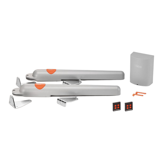
  • Page 2 ARIA200M ARIA400M CLB202 CLB203 ECCO5WO FL200 PH200 ECCO5BO KIT ARIA200 ARIA200M n° 2 ARIA200M CLB202 n° 1 CLB202 FL200 n° 1 FL200 PH200 un paio PH200 ECCO5WO n° 1 ECCO5WO ECCO5BO n° 1 ECCO5BO KIT ARIA200START ARIA200M n° 1 ARIA200M CLB202 n°...
  • Page 3 Step FL200 CLB202 CLB203 PH200 PH200 PH200 PH200 ARIA200 ARIA400 ARIA200 ARIA400 A B C D • Voir le tableau 2 (paragraphe 3.4) • - See Table 2 (Par. 3.4) • - Vedere Tabella 2 (parag. 3.4) • - Patrz Tabela 2 (punkt 3.4)
  • Page 4 ➠ 740mm ➠...
  • Page 5 ➠ 180° 740mm 180°...
  • Page 6 Installation des photocellules > fig. 5 - paragraphe 3.6 Installation of photocells > Fig. 5 - Paragraph 3.6 PH200 Installazione fotocellule > fig. 5 - paragrafo 3.6 Montaż fotokomórek > rys. 5 - punkt 3.6 Installation du clignotant > fig. 6 - paragraphe 3.7 Installation of photocells >...
  • Page 7 PH200 Ø < 5 mm Led SAFE...
  • Page 8 FL200 05. A Ø = 6 mm 05. B Ø = 6 mm (flash) (aerial) VIII...
  • Page 9 Step brun • - brown • - marrone • - brązowy - jaune-vert • - yellow/ green • - giallo/verde • - żółty/zielony bleu • - blue • - blu • - niebieski led Stop led SbS led ECSbus FLASH STOP F 2AF Après avoir raccordé...
  • Page 10 Step Voir le chapitre 5 pour procéder au premier allumage du système. Cette phase doit être effectuée exclusivement par un électricien qualifié. To start-up the system, see Chapter 5. This phase must be carried exclusively by a qualified electrician. Per procedere con la prima accensione dell'impianto, vedere il capitolo 5. Questa fase deve essere eseguita esclusivamente da un elettricista qualificato.
  • Page 11: Table Des Matières

    SOMMAIRE GUIDE RAPIDE (images seulement) II-X 1 RECOMMANDATIONS GÉNÉRALES : SÉCURITÉ - INSTALLATION - UTILISATION 2 DESCRIPTION DU PRODUIT ET APPLICATION 3 INSTALLATION 3.1 VÉRIFIER QUE LE PORTAIL EST COMPATIBLE ET QUE L’ENVIRONNEMENT EST ADAPTÉ 3.2 - VÉRIFIER LES LIMITES D’APPLICATION DU PRODUIT 3.3 CARACTÉRISTIQUES TECHNIQUES DU PRODUIT 3.4 TRAVAUX PRÉLIMINAIRES AVANT L’INSTALLATION 3.5 INSTALLATION DE L’OPÉRATEUR ARIA (MOD.400C/600C) ET LOGIQUE CLB (MOD.
  • Page 13: Recommandations Générales : Sécurité - Installation - Utilisation

    RECOMMANDATIONS GÉNÉRALES : SÉCURITÉ - INSTALLATION - UTILISATION (instructions originales en italien) ATTENTION Instructions importantes pour la sécurité. Il est important de suivre toutes les instructions fournies étant donné qu’une installation incorrecte est susceptible de provoquer des dommages graves ATTENTION Instructions importantes pour la sécurité. Pour la sécurité des personnes, il est important de suivre ces instructions. Conserver ces instructions •...
  • Page 14: Description Du Produit Et Application

    ECSbus (un câble unique avec deux conducteurs électriques). La logique de commande peut être alimentée par le secteur (230 V ) ou par le système photovoltaïque SOLEKIT de la ligne Nice Home. Si elle est alimentée par le secteur, elle peut être associée à...
  • Page 15: Travaux Avant L'installation

    Auto-détection de l’automatisme avec 1 ou 2 moteurs Remarque  : dans le but d’améliorer les produits, NICE S.p.a. se réserve le droit d’en modifier à tout moment et sans préavis les caractéristiques techniques, en garantissant dans tous les cas le bon fonctionnement et le type d’utilisation prévus. Note : toutes les caractéristiques techniques se réfèrent à...
  • Page 16: Installation Opérateur Aria 200M/400M

    ** Pour les câbles ECSbus (1) et ceux des entrées Stop et SbS, il est possible d’utiliser aussi un seul câble avec plusieurs conducteurs internes pour regrouper plusieurs connexion : par exemple, les entrées Stop et SbS peuvent être connectées au sélecteur KS100 avec un câble de 4 x 0,5 mm (1) ATTENTION ! –...
  • Page 17: Connexion Électrique À La Logique

    Step RACCORDEMENTS ÉLECTRIQUES 4.1 - CONNEXION ÉLECTRIQUE À LA LOGIQUE DE COMMANDE (fig. 7) 01. Connecter les différents dispositifs du kit et tous les autres composants prévus pour l’installation (en option et non inclus dans l’emballage), aux bornes de la logique de commande (fig. 7) : il n’est pas nécessaire de respecter la polarité, sauf celle du câble blindé de l’antenne qui doit être connecté...
  • Page 18: Mémorisation Des Angles D'ouverture Et De Fermeture Des Vantaux Du Portail

    STOP 5.4 - MÉMORISATION DES ANGLES D’OUVERTURE ET DE FERMETURE DES VANTAUX DU PORTAIL Après la reconnaissance des dispositifs (paragraphe 5.3), Il faut faire reconnaître à la logique de commande les angles d’ouverture des vantaux. Dans cette phase, l’angle d’ouverture des vantaux est mesuré de la butée mécanique de fermeture jusqu’à la butée mécanique d’ouverture. La présence de butées mécaniques fixes et suffisamment solides est indispensable.
  • Page 19: Procédure De Mémorisation

    TABLEAU 1 Touches Commande associée Pas à pas (SbS) Ouverture piétonne Ouverture seule Fermeture seule Non utilisé dans cette application Procédure de mémorisation 01. Sur la logique de commande (fig. 19), appuyer et maintenir enfoncée la touche P1 pendant 3 secondes. Quand la led L1 s’allume, relâcher la touche.
  • Page 20: Essai Et Mise En Service

    ESSAI ET MISE EN SERVICE ATTENTION ! – L’essai et la mise en service de l’automatisme doivent être effectués par du personnel qualifié et expérimenté qui devra se charger d’établir les essais prévus en fonction des risques présents et vérifier le respect de ce qui est prévu par les lois, les normes et les réglementations ;...
  • Page 21: Informations Complémentaires

    INFORMATIONS COMPLÉMENTAIRES 9.1 - RÉGLAGES AVANCÉS 9.1.1 - Réglage des paramètres (à l’aide de l’émetteur mémorisé en Mode 1) Avec l’émetteur, il est possible de régler certains paramètres de fonctionnement de la logique de commande : • Temps de pause : temps pendant lequel les vantaux restent ouverts avant une fermeture automatique (si la fonction « cycle complet » est program- mée), voir paragraphe 9.1.1.1 •...
  • Page 22: Procédure De Réglage Des Paramètres : Configuration Entrée Sbs - Configuration Sortie

    9.1.1.2 - Procédure de réglage des paramètres : Configuration entrée SbS - Configuration sortie Flash - Déchargement Moteur 1 et 2 en fermeture - Déchargement Moteur 1 et 2 en ouverture Avant de continuer, vérifier dans le tableau 3 le paramètre à modifier et l’action à effectuer: 01.
  • Page 23: Ajout Ou Enlèvement De Dispositifs

    Il est possible d’ajouter ou de supprimer à tout moment des dispositifs dans l’installation : dans le cas d’ajout de dispositifs, il est important de vérifier que ces derniers sont parfaitement compatibles avec ARIA 200M/400M. Pour en savoir plus, consulter le service après-vente Nice.
  • Page 24: Annulation De La Mémoire De Chaque Émetteur Depuis La Mémoire De La Logique

    05. Sur l’ANCIEN émetteur, appuyer et maintenir appuyée n’importe quelle touche à copier pendant au moins 2 secondes puis la relâcher. 06. Sur le NOUVEL émetteur, appuyer et maintenir appuyée n’importe quelle touche à mémoriser pendant au moins 5 secondes puis la relâcher. Répéter cette procédure pour chaque émetteur à...
  • Page 25: Diagnostic Et Signalisations Des Dispositifs

    9.8 - DIAGNOSTIC ET SIGNALISATIONS DES DISPOSITIFS Certains dispositifs sont prévus pour émettre des signalisations permettant de détecter l’état de fonction- nement ou les éventuelles anomalies. 9.8.1 - Signalisations des photocellules SAFE Les photocellules contiennent une led SAFE (fig. 32) qui permet de vérifier à tout moment l’état de leur fonctionnement, voir le Tableau 8.ù...
  • Page 26: Spécifications

    Pour plus de détails sur les dispositifs ECSbus, consulter le catalogue des produits de la gamme Nice Home ou visiter le site www.niceforyou.fr Grâce à un processus De reconnaissance, la logique de commande reconnaît un par un tous les dispositifs connectés et cela permettra de détecter avec une sécurité...
  • Page 27: Graphique

    Indice de charge de travail GRAPHIQUE 1 TABLEAU 12 ARIA200M ARIA400M 125.000 > 100 kg > 200 kg 100.000 Poids du vantail > 300 kg > 400 kg 75.000 1 - 1,5 m 1,5 - 2,5 m 50.000 Longueur du vantail 2,5 - 3,5 25.000 3,5 - 4,5...
  • Page 28: Déclaration Ce De Conformité

    Déclaration conforme aux Directives : 1999/5/CE (R&TTE), 2014/30/UE (EMC); 2006/42/CE (MD) annexe II, partie B Note - Le contenu de cette déclaration de conformité correspond à ce qui est déclaré dans le document officiel, déposé au siège de Nice S.p.a., et en particulier à...
  • Page 29: Recommandations

    NOTICE D’UTILISATION (à remettre à l’utilisateur final) Il est conseillé de conserver cette notice et de la remettre à tous les utilisateurs de l’automatisme. 11.1 – RECOMMANDATIONS • Surveiller le portail en mouvement et se tenir à une distance de sécurité tant qu’il n’est pas complètement ouvert ou fermé ; ne pas transiter dans le passage tant que le portail n’est pas complètement ouvert ou fermé.
  • Page 30: Déclaration De Conformité Ce

    ANNEXE I DÉCLARATION DE CONFORMITÉ CE Selon la Directive 2006/42/CE, ANNEXE I, partie A (déclaration CE de conformité pour les machines) –––––––––––––––––––– Le soussigné / la société (nom ou raison sociale de la personne/société qui a mis en service le portail motorisé) : ..
  • Page 31 CONTENTS QUICK GUIDE (images only) II-X 1 GENERAL WARNINGS: SAFETY - INSTALLATION - USE 2 PRODUCT DESCRIPTION AND INTENDED USE 3 INSTALLATION 3.1 VERIFYING THE SUITABILITY OF THE GATE AND ENVIRONMENT 3.2 VERIFYING THE PRODUCT’S APPLICATION LIMITS 3.3 PRODUCT TECHNICAL SPECIFICATIONS 3.4 PRE-INSTALLATION WORKS 3.5 INSTALLING THE ARIA GEARMOTORS (models 400C/600C) and CLB CONTROL UNIT (models 202/203) 3.5.1...
  • Page 33: General Warnings: Safety - Installation - Use

    GENERAL WARNINGS: SAFETY - INSTALLATION - USE (original instructions in Italian) CAUTION Important safety instructions. Observe all the instructions as improper installation may cause serious damage CAUTION Important safety instructions. It is important to comply with these instructions to ensure personal safety. Store these instructions •...
  • Page 34: Product Description And Intended Use

    PRODUCT DESCRIPTION AND INTENDED USE The devices of this kit and other optional accessories belong to the Nice Home automation system and are designed to automate a swinging gate for residential use. CAUTION! – Any use other than that specified herein or in environmental conditions other than those stated in this manual is to be con- sidered improper and is forbidden The kit comprises two electromechanical gearmotors with 24 V direct current;...
  • Page 35: Pre-Installation Works

    Automation auto-detection with 1 or 2 motors Note: in order to improve its products, NICE S.p.A. reserves the right to modify their technical specifications at any time without prior notice. In any case, the manufacturer guarantees their functionality and suitability for their intended use. Note: all technical specifications refer to a temperature of 20°C.
  • Page 36: Installing The Aria Gearmotors 200M/400M

    3.5 - INSTALLING THE ARIA GEARMOTORS model 200M/400M and CONTROL UNIT model CLB 202/203 • All installation operations must be made with the system disconnected from the power supply. If the back-up battery is present, it must be disconnected • Incorrect installation may cause serious physical injury to those working on or using the system. •...
  • Page 37: Electrical Connections

    Step ELECTRICAL CONNECTIONS 4.1 - ELECTRICAL CONNECTION TO THE CONTROL UNIT (Fig. 7) 01. Connect the various kit devices and any other components designed for being used on the system (optional and not included in the package) to the control unit terminals (Fig. 7): for all accessories it is not necessary to observe any polarity, with the exception of the shielded aerial cable which must be connected with the cable and sheath as shown.
  • Page 38: Memorisation Of Gate Leaf Opening And Closing Angles

    STOP 5.4 - MEMORISATION OF GATE LEAF OPENING AND CLOSING ANGLES After recognition of the devices (Par. 5.3), the control unit must recognise the opening angles of the leaves. In this phase the system reads the leaf open- ing angle from the mechanical closing stop to the mechanical opening stop. The presence of fixed and sufficiently strong mechanical stops is essential. 01.
  • Page 39: Basic Adjustments

    TABLE 1 Keys Paired command Step-by-Step (SbS) Pedestrian opening Open only Close only Not used in this application Memorisation procedure 01. On the control unit (Fig. 19) press and hold key P1 for 3 seconds; when led L1 switches on, release the key. 02.
  • Page 40: Testing And Commissioning

    TESTING AND COMMISSIONING CAUTION! – The system must be tested by skilled and qualified personnel, who is responsible for defining the tests adopted in rela- tion to the risks present, and for ensuring observance of all legal provisions, standards and regulations, with particular reference to all requirements of the EN 13241-1, EN 12445 and EN 12453 standards which defines the test methods for testing gate automations.
  • Page 41: Further Information

    FURTHER INFORMATION 9.1 - ADVANCED SETTINGS 9.1.1 - Adjusting the parameters (using the transmitter memorised in Mode 1) The transmitter can be used to set a number of control unit operating parameters: • Pause time: time during which the gate leaves remain open before re-closing automatically (if the “complete cycle” function is set); see Par. 9.1.1.1 •...
  • Page 42: Parameter Adjustment Procedure: Sbs Input Configuration - Flash Output Configuration - Discharging Of Motor

    9.1.1.2 - Parameter adjustment procedure: SbS input configuration - Flash output configura- tion - Discharging of Motor 1 and 2 upon closing - Discharging of Motor 1 and 2 upon opening Before proceeding, check the parameter to be modified in Table 3 and the action to be performed: 01.
  • Page 43: Adding Or Removing Devices

    It is possible to add or remove devices at any time to the system: if devices are added, it is important to verify that these are perfectly compatible with ARIA 200M/400M; for further details contact the Nice technical support service.
  • Page 44: Deleting The Memory Of The Individual Transmitter From The Control Unit's Memory

    06. On the NEW transmitter, press and hold any key to be memorised for at least 5 seconds then release it. Repeat the procedure for each transmitter to be memorised. • Procedure with OLD transmitter memorised in Mode 2: 01. Draw near the control unit with the two transmitters: wait 1 second between two successive steps.
  • Page 45: Diagnostics And Device Signals

    9.8 - DIAGNOSTICS AND DEVICE SIGNALS Certain devices are configured to display messages to identify their operating status or any anomalies. 9.8.1 - Photocell signals SAFE The photocells contain a SAFE led (Fig. 32) that allows for verifying their operating status at any time: see Table 8.
  • Page 46: Specifications

    Photocells and other devices adopting this system can be connected to the ECSbus, such as safety devices, control buttons, indicator lights etc. For information on ECSbus devices, consult the Nice Home range product catalogue or visit the website www.niceforyou.com Through a recognition procedure the control unit recognises one-by-one all the devices connected and this enables it to detect with extreme precision all possible anomalies during the automation’s normal operation.
  • Page 47: Troubleshooting

    Severity index GRAPH 1 TABLE 12 ARIA200M ARIA400M 125.000 > 100 kg > 200 kg 100.000 Weight of the leaf > 300 kg > 400 kg 75.000 1 – 1.5 m 50.000 1.5 – 2.5 m Length of the leaf 2.5 –...
  • Page 48 Declaration in accordance with the following Directives: 1999/5/EC (R&TTE), 2014/30/EU (EMC); 2006/42/EC (MD) Annex II, Part B Note - The contents of this declaration correspond to that stated in the official document filed in the offices of Nice S.p.A. and, in particular, the latest version thereof available prior to the print- ing of this manual.
  • Page 49: Manually Releasing And Locking The Gearmotor

    USER MANUAL (to be delivered to the end user) This user guide should be stored and handed to all user’s of the automation. 11.1 – WARNINGS • Monitor the gate while it is moving and keep at a safe distance until it is fully open or closed; do not transit through it until the gate is fully open and stopped.
  • Page 50: Ec Declaration Of Conformity

    ANNEX 1 EC DECLARATION OF CONFORMITY In conformity to Directive 2006/42/EC, ANNEX I, Part A (EC declaration of conformity for machinery) –––––––––––––––––––– The undersigned / company (name or company name of the subject who/that commissioned the motor-driven gate): ....
  • Page 51 SOMMARIO GUIDA RAPIDA (solo immagini) II-X 1 AVVERTENZE GENERALI: SICUREZZA - INSTALLAZIONE - USO 2 DESCRIZIONE DEL PRODOTTO E DESTINAZIONE D'USO 3 INSTALLAZIONE 3.1 VERIFICARE L'IDONEITÀ DEL CANCELLO E DELL’AMBIENTE 3.2 VERIFICARE I LIMITI D’IMPIEGO DEL PRODOTTO 3.3 CARATTERISTICHE TECNICHE DEL PRODOTTO 3.4 LAVORI PRELIMINARI ALL’INSTALLAZIONE 3.5 INSTALLAZIONE DEL MOTORIDUTTORI ARIA (mod.400C/600C) e CENTRALE CLB (mod.
  • Page 53: Avvertenze Generali: Sicurezza - Installazione - Uso

    AVVERTENZE GENERALI: SICUREZZA - INSTALLAZIONE - USO (istruzioni originali in italiano) ATTENZIONE Istruzioni importanti per la sicurezza. Seguire tutte le istruzioni poiché l’installazione non corretta può causare gravi danni ATTENZIONE Istruzioni importanti per la sicurezza. Per la sicurezza delle persone è importante seguire queste istruzioni. Conser- vare queste istruzioni •...
  • Page 54: Descrizione Del Prodotto E Destinazione D'uso

    INSTALLAZIONE Alcuni dispositivi e accessori citati in questo manuale sono opzionali e non presenti nel kit. I fermi di finecorsa, non sono presenti nel kit e non fanno parte dei prodotti della linea Nice Home. Consultare il catalogo dei prodotti della linea Nice Home o visitare il sito www.niceforyou.com 3.1 - VERIFICARE L'IDONEITÀ DEL CANCELLO E DELL’AMBIENTE •...
  • Page 55: Lavori Preliminari All'installazione

    Autorilevazione del tipo di dispositivo di Stop (contatto NA, NC o resistenza 8,2 kΩ) Autorilevazione degli angoli di apertura di ogni anta Autorilevazione automazione con 1 o 2 motori Nota: allo scopo di migliorare i prodotti, NICE S.p.A. si riserva il diritto di modificare le caratteristiche tecniche in qualsiasi momento e senza preavviso, garantendo comunque funzionalità e destinazione d’uso previste. Nota: tutte le caratteristiche tecniche sono riferite alla temperatura di 20°C. 3.4 - LAVORI PRELIMINARI ALL’INSTALLAZIONE Prendendo spunto dalla fig. 2, stabilire la posizione approssimativa d'installazione di ogni dispositivo previsto nell’impianto; i vari elementi sono posi- zionati secondo uno schema standard ed usuale.
  • Page 56: Installazione Motoriduttori Aria 200M/400M

    ** Per i cavi ECSbus (1) e quelli degli ingressi Stop e SbS, è possibile utilizzare anche un singolo cavo con più conduttori interni, per raggruppare più collegamenti: ad esempio, gli ingressi Stop e SbS possono essere collegati al selettore KS100 con un cavo da 4 x 0,5 mm (1) ATTENZIONE! – I cavi ECSbus devono essere posizionati in canaline diverse rispetto ai cavi dei motori. ATTENZIONE! – I cavi utilizzati devono essere adatti al tipo di ambiente in cui avviene l’installazione: ad esempio si consiglia un cavo tipo H03VV-F per la posa in ambient interno, oppure tipo H07RN-F per la posa in ambiente esterno.
  • Page 57: Collagamenti Elettrici

    Step COLLEGAMENTI ELETTRICI 4.1 - COLLEGAMENTO ELETTRICO ALLA CENTRALE (fig. 7) 01. Collegare i vari dispositivi del kit ed altri eventuali componenti previsti per l'impianto (opzionali e non presenti nella confezione), ai morsetti della centrale (fig. 7): per tutti gli accessori non è necessario rispettare alcuna polarità, ad eccezione del cavo schermato dell’antenna che deve essere collegato il cavo e la calza come indicato. Per il collegamento dei motoriduttori vedere il particolare di fig. 8.
  • Page 58: Memorizzazione Degli Angoli Di Apertura E Chiusura Delle Annte Del Cancello

    STOP 5.4 - MEMORIZZAZIONE DEGLI ANGOLI DI APERTURA E CHIUSURA DELLE ANTE DEL CANCELLO Dopo l’apprendimento dei dispositivi (paragr. 5.3), è necessario far riconoscere alla centrale gli angoli di apertura delle ante. In questa fase viene rilevato l’angolo di apertura della ante dall’arresto meccanico di chiusura fino all’arresto meccanico di apertura. È indispensabile la presenza di arresti meccanici fissi e sufficientemente robusti. 01. Effettuare lo sblocco manuale dei motoriduttori (fig. 14) e portare le ante a metà corsa in modo che siano libere di muoversi in apertura e chiusura; poi bloccare i motori (fig.
  • Page 59: Procedura Di Memorizzazione

    TABELLA 1 Tasti Comando abbinato Passo Passo (SbS) Apertura pedonale Solo apre Solo chiude Non utilizzato in questa applicazione Procedura di memorizzazione 01. Sulla centrale (fig. 19) premere e mantenere premuto il tasto P1 per 3 secondi; quando il led L1 si accende, rilasciare il tasto. 02. Entro 10 secondi dal rilascio, premere e mantenere premuto per 3 secondi un tasto qualsiasi del trasmettitore da memorizzare. Se la memorizzazione è andata a buon fine il led P1 (sulla centrale) emette 3 lampeggi.
  • Page 60: Collaudo E Messa In Servizio

    COLLAUDO E MESSA IN SERVIZIO ATTENZIONE! – Il collaudo e la messa in servizio dell’automazione deve essere eseguita da personale qualificato ed esperto che dovrà farsi carico di stabilire le prove previste in funzione dei rischi presenti e di verificare il rispetto di quanto previsto da leggi, norma- tive e regolamenti, ed in particolare tutti i requisiti delle norme EN 13241-1, EN 12445 ed EN 12453 che stabilisce i metodi di prova per la verifica degli automatismi per cancelli.
  • Page 61: Approfondimenti

    APPROFONDIMENTI 9.1 - REGOLAZIONI AVANZATE 9.1.1 - Regolazione dei parametri (usando il trasmettitore memorizzato in Modo 1) Con il trasmettitore è possibile regolare alcuni parametri di funzionamento della centrale: • Tempo pausa: tempo nel quale le ante restano aperte prima di una richiusura automatica (se è impostata la funzione “ciclo completo”); vedere paragr. 9.1.1.1 • Apertura pedonale: modalità di apertura parziale delle ante, per il passaggio di pedoni; vedere paragr. 9.1.1.1 •...
  • Page 62: Verifica Dei Valori Impostati Per Ciascun Parametro (Usando Il Trasmettitore)

    9.1.1.2 - Procedura di regolazione dei parametri: Configurazione ingresso SbS - Configurazione uscita Flash - Scaricamento Motore 1 e 2 in chiusura - Scaricamento Motore 1 e 2 in apertura Prima di procedere, verificare nella Tabella 3 il parametro da modificare e l'azione da eseguire: 01.
  • Page 63: Aggiunta O Rimozione Dei Dispositivi

    9.2 - AGGIUNTA O RIMOZIONE DEI DISPOSITIVI Nell'impianto realizzato, è possibile aggiungere o rimuovere dispositivi in qualsiasi momento: nel caso di aggiunta dispositivi, è importante verificare che questi siano perfettamente compatibili con ARIA 200M/400M; per ulteriori dettagli consultare il servizio as sistenza Nice. 9.2.1 - Memorizzazione di ulteriori dispositivi Normalmente l’operazione di apprendimento dei dispositivi collegati all’ECSbus e all’ingresso Stop viene eseguita durante la fase d'installazione, ma se vengono aggiunti (o rimossi) dispositivi successivamente, è...
  • Page 64: Cancellazione Memoria Del Singolo Trasmettitore Dalla Memoria Della Centrale

    05. Sul VECCHIO trasmettitore premere e mantenere premuto un tasto qualsiasi da copiare per almeno 2 secondi e poi rilasciarlo. 06. Sul NUOVO trasmettitore premere e mantenere premuto un tasto qualsiasi da memorizzare per almeno 5 secondi e poi rilasciarlo. Ripetere la procedura per ogni trasmettitore da memorizzare. • Procedura con trasmettitore VECCHIO memorizzato in Modo 2: 01.
  • Page 65: Diagnostica E Segnalazioni Dei Dispositivi

    9.8 - DIAGNOSTICA E SEGNALAZIONI DEI DISPOSITIVI Alcuni dispositivi sono predisposti per emettere delle segnalazioni con il quale riconoscere lo stato di funzionamento oppure di eventuali anomalie. SAFE 9.8.1 - Segnalazioni delle fotocellule Nelle fotocellule è presente il led SAFE (fig. 32) che permette di verificare in qualsiasi momento il loro stato di funzionamento: vedere Tabella 8.
  • Page 66: Specifiche

    Ad ECSbus si possono collegare le fotocellule e altri dispositivi che adottano questo sistema come, ad esempio, i dispositivi di sicurezza, i pulsanti di comando, le spie di segnalazione ecc. Per informazioni sui dispositivi ECSbus consultare il catalogo dei prodotti della linea Nice Home o il sito www. niceforyou.com Attraverso una procedura di apprendimento la centrale riconosce uno ad uno tutti i dispositivi collegati e questo le permetterà di rilevare con estrema...
  • Page 67: Risoluzione Dei Problemi

    Indice di gravosità GRAFICO 1 TABELLA 12 ARIA200M ARIA400M 125.000 > 100 kg > 200 kg 100.000 Peso dell’anta > 300 kg > 400 kg 75.000 1 - 1,5 m 50.000 1,5 - 2,5 m Lunghezza dell’anta 2,5 - 3,5 25.000 3,5 - 4,5 Temperatura ambientale superiore a 40°C o infe-...
  • Page 68: Dichiarazione Ce Di Conformità

    Dichiarazione in accordo alle Direttive: 1999/5/CE (R&TTE), 2014/30/UE (EMC); 2006/42/CE (MD) allegato II, parte B Nota - Il contenuto di questa dichiarazione corrisponde a quanto dichiarato nel documento ufficiale depositato presso la sede di Nice S.p.a., e in particolare, alla sua ultima revisione disponibi- le prima della stampa di questo manuale. Il testo qui presente è stato riadattato per motivi editoriali. Copia della dichiarazione originale può essere richiesta a Nice S.p.a. (TV) Italy.
  • Page 69: Guida All'uso (Da Consegnare All'utilizzatore Finale)

    GUIDA ALL’USO (da consegnare all'utilizzatore finale) Si consiglia di conservare questa guida all'uso e consegnarla a tutti gli utilizzatori dell’automatismo. 11.1 – AVVERTENZE • Sorvegliare il cancello in movimento e tenersi a distanza di sicurezza finchè non si sia completamente aperto o chiuso; non transitare nel passaggio fino a che il cancello non sia completamente aperto e fermo.
  • Page 70: Allegato I (Inserto Staccabile)

    ALLEGATO I DICHIARAZIONE DI CONFORMITÀ CE Secondo la direttiva 2006/42/CE ALLEGATO I parte A (dichiarazione CE di conformità per le macchine) –––––––––––––––––––– Il sottoscritto / ditta (nome o ragione sociale di chi ha messo in servizio il cancello motorizzato): ..................... . Indirizzo: ................
  • Page 71 SPIS TREŚCI INSTRUKCJA SKRÓCONA (tylko rysunki) II-X 1 OGÓLNE OSTRZEŻENIA: BEZPIECZEŃSTWO - MONTAŻ - UŻYTKOWANIE 2 OPIS URZĄDZENIA I JEGO PRZEZNACZENIE 3 MONTAŻ 3.1 KONTROLA ODPOWIEDNIOŚCI BRAMY DO ZAUTOMATYZOWANIA I OTOCZENIA 3.2 KONTROLA OGRANICZEŃ ZWIĄZANYCH Z ZASTOSOWANIEM PRODUKTU 3.3 PARAMETRY TECHNICZNE PRODUKTU 3.4 PRACE WSTĘPNE DO WYKONANIA PRZED MONTAŻEM 3.5 MONTAŻ...
  • Page 73: Ogólne Ostrzeżenia: Bezpieczeństwo - Montaż - Użytkowanie

    OGÓLNE OSTRZEŻENIA: BEZPIECZEŃSTWO - MONTAŻ - UŻYTKOWANIE (Oryginalna instrukcja w języku włoskim) UWAGA Ważne instrukcje bezpieczeństwa. Należy przestrzegać wszystkich instrukcji, ponieważ nieprawidłowy montaż może być przyczyną poważnych szkód UWAGA Ważne instrukcje bezpieczeństwa. W celu zapewnienia bezpieczeństwa osób, postępować zgodnie z niniejszą in- strukcją.
  • Page 74: Opis Urządzenia I Jego Przeznaczenie

    OPIS URZĄDZENIA I JEGO PRZEZNACZENIE Urządzenia zawarte w niniejszym zestawie wraz z akcesoriami opcjonalnymi należą do systemu automatyki Nice Home i są przeznaczone do automatyzacji bramy skrzydłowej do użytku prywatnego. UWAGA! – Wszelkie inne użycie, różne od opisanego oraz wykorzystywanie produktu w warunkach otoczenia odmiennych, niż te, przedstawione w niniejszej instrukcji jest niezgodne z przeznaczeniem i zabronione Zestaw składa się...
  • Page 75: Kontrole Wstępne Przed Montażem

    Automatyczne rozpoznawanie automatyki z 1 lub 2 silnikami Uwaga: w celu poprawy własnych produktów, firma Nice S.p.a. zastrzega sobie prawo wprowadzania zmian parametrów technicznych własnych produktów w którejkolwiek chwili i bez uprzedzenia, ale gwarantując ich funkcjonalność i przewidziane zastosowanie. Uwaga: charakterystyka techniczna odnosi się...
  • Page 76: Montaż Motoreduktorów Aria 200M/400M

    * Możliwe jest użycie kabla zasilającego dłuższego od 30 m, pod warunkiem, że będzie on posiadał większy przekrój (np. 3 x 2,5 mm ) i, że w pobliżu automatyki zostanie przewidziane uziemienie. ** W przypadku kabli ECSbus (1) i kabli wejść Stop i SbS możliwe jest również użycie pojedynczego kabla z większą liczbą przewodów wewnętrz- nych w celu zgrupowania większej liczby połączeń: na przykład wejścia Stop i SbS mogą...
  • Page 77: Połączenia Elektryczne

    Step POŁĄCZENIA ELEKTRYCZNE 4.1 - PODŁĄCZENIE ELEKTRYCZNE DO CENTRALI (rys. 7) 01. Podłączyć poszczególne urządzenia zestawu i ewentualne inne komponenty, które mają być częścią instalacji (opcjonalne, niezawarte w opako- waniu) do zacisków centrali (rys. 7): nie jest konieczne przestrzeganie żadnej biegunowości w przypadku wszystkich akcesoriów z wyjątkiem kabla ekranowanego anteny, gdzie kabel i oplot należy połączyć...
  • Page 78: Wczytywanie Kątów Otwarcia I Zamknięcia Skrzydeł Bramy

    STOP 5.4 - WCZYTYWANIE KĄTÓW OTWARCIA I ZAMKNIĘCIA SKRZYDEŁ BRAMY Po wczytaniu urządzeń (punkt 5.3), należy umożliwić centrali wczytanie kątów otwarcia skrzydeł. W tej fazie zostaje odczytany kąt otwarcia skrzydła od zatrzymania mechanicznego podczas zamykania do zatrzymania mechanicznego podczas otwierania. Konieczna jest obecność stałych, odpowiednio solidnych blokad mechanicznych.
  • Page 79: Regulacje Podstawowe

    TABELA 1 Przy- Polecenie przypisane ciski Krok Po Kroku (SbS) Otwarcie dla pieszych Tylko otwiera Tylko zamyka Nie wykorzystywany w tym zastosowaniu Procedura wczytywania 01. Na centrali (rys. 19) nacisnąć i przytrzymać wciśnięty przycisk P1 przez 3 sekundy; gdy dioda L1 zapali się, zwolnić przycisk. 02.
  • Page 80: Odbiór I Przekazanie Do Eksploatacji

    ODBIÓR I PRZEKAZANIE DO EKSPLOATACJI UWAGA! – Próba odbiorcza i przekazanie automatyki do eksploatacji powinny być wykonane przez wykwalifikowany i doświadczony personel, który powinien wykonać przewidziane testy w zależności od istniejących zagrożeń. Należy sprawdzić przestrzeganie prze- pisów, norm i rozporządzeń i, w szczególności, spełnienie wymagań norm EN 13241-1, EN 12445 i EN 12453, które określają metody testów do kontroli automatyki bram.
  • Page 81: Informacje Dodatkowe

    INFORMACJE DODATKOWE 9.1 - REGULACJE ZAAWANSOWANE 9.1.1 - Regulacja parametrów (przy użyciu nadajnika wczytanego w Trybie 1) Nadajnik radiowy umożliwia ustawienie niektórych parametrów funkcjonowania centrali: • Czas pauzy: czas, podczas którego skrzydła pozostają otwarte przed ich automatycznym zamknięciem (jeśli jest ustawiona funkcja „cykl automa- tyczny“);...
  • Page 82: Procedura Regulacji Parametrów: Konfiguracja Wejścia Sbs - Konfiguracja Wyjścia Flash - Rozładowanie Silnika 1 I

    9.1.1.2 - Procedura regulacji parametrów: Konfiguracja wejścia SbS - Konfiguracja wyjścia Flash - Rozładowanie silnika 1 i 2 podczas zamykania - Rozładowanie silnika 1 i 2 podczas otwierania Przed rozpoczęciem, sprawdzić w Tabeli 3 parametr do zmiany i działanie, jakie należy wykonać: 01.
  • Page 83: Dodawanie Lub Usuwanie Urządzeń

    W zrealizowanej instalacji można w dowolnej chwili dodać lub usunąć urządzenia: w przypadku dodawania urządzeń, należy się upewnić, że są one w pełni kompatybilne z ARIA 200M/400M; w celu uzyskania dodatkowych informacji należy się skontaktować z serwisem technicznym Nice. 9.2.1 - Wczytywanie kolejnych nadajników Zazwyczaj, czynność...
  • Page 84: Kasowanie Pamięci Pojedynczego Nadajnika Z Pamięci Centrali

    05. Na STARYM nadajniku nacisnąć i przytrzymać wciśnięty dowolny przycisk do skopiowania przez co najmniej 2 sekundy, a następnie go zwolnić. 06. Na NOWYM nadajniku nacisnąć i przytrzymać wciśnięty dowolny przycisk do wczytania przez co najmniej 5 sekund, a następnie go zwolnić. Powtórzyć...
  • Page 85: Diagnostyka I Sygnalizacje Urządzeń

    9.8 - DIAGNOSTYKA I SYGNALIZACJA URZĄDZEŃ Niektóre urządzenia są w stanie wydawać sygnały informujące o stanie roboczym lub ewentualnych usterkach. SAFE 9.8.1 - Sygnalizacje fotokomórek W fotokomórkach znajduje się dioda SAFE (rys. 32) umożliwiająca sprawdzenie, w każdej chwili, stanu funkcjonowania: patrz Tabela 8. TABELA 8 Dioda SAFE (rys.
  • Page 86: Specyfikacje

    Do ECSbus można podłączyć zarówno fotokomórki, jak i inne urządzenia stosujące ten system, na przykład urządzenia bezpieczeństwa, przyciski sterowania, diody sygnalizacyjne itp. Informacje na temat urządzeń ECSbus są dostępne w katalogu produktów linii Nice Home lub na stronie www. niceforyou.com Za pomocą...
  • Page 87: Rozwiązywanie Problemów

    Wskaźnik trudności WYKRES 1 TABELA 12 ARIA200M ARIA400M 125.000 > 100 kg > 200 kg 100.000 Masa skrzydła > 300 kg > 400 kg 75.000 1 - 1,5 m 50.000 1,5 - 2,5 m Długość skrzydła 2,5 - 3,5 25.000 3,5 - 4,5 Temperatura otoczenia wyższa niż...
  • Page 88 Język: PL Nazwa producenta: NICE S.p.A. - Adres: Via Pezza Alta N°13, 31046 Rustignè di Oderzo (TV) Italy - Osoba upoważniona do sporządzenia dokumentacji technicznej: NICE S.p.A. - Typ produktu: Motoreduktor 24 Vdc do bram skrzydłowych - Model / Typ: ARIA200M, ARIA400M, CLB202, CLB203 - Akcesoria: PR100, ECCO5BO, ECCO5WO, PH200, FL200 Niżej podpisany, Roberto Griffa, Chief Executive Officer, oświadcza na własną...
  • Page 89: Konserwacja Do Wykonania Przez Użytkownika

    INSTRUKCJA OBSŁUGI (do dostarczenia końcowemu użytkownikowi) Zalecamy zachować instrukcję i przekazywać ją wszystkim użytkownikom urządzenia. 11.1 – OSTRZEŻENIA • Nadzorować bramę podczas jej przesuwania się i zachować bezpieczną odległość do momentu, gdy brama zostanie całkowicie otwarta lub zamknięta; nie przechodzić przez bramę dopóki nie otworzy się całkowicie i nie zatrzyma. •...
  • Page 90: Deklaracja Zgodności Ce

    ZAŁĄCZNIK I DEKLARACJA ZGODNOŚCI CE Zgodnie z dyrektywą 2006/42/WE, ZAŁĄCZNIK I, część A (deklaracja zgodności CE dla maszyn) –––––––––––––––––––– Niżej podpisany/firma (nazwisko lub nazwa firmy, która oddała do użytku bramę z napędem): ....
  • Page 92 Service Après Vente France En cas de panne, merci de contacter obligatoirement notre Service Après Vente par téléphone ou par email : 0 820 859 203 Service 0,15 €/min + prix appel niceservice@niceforyou.com Merci de ne pas retourner le produit en magasin Worldwide Customer Service customerservice@niceforyou.com Nice S.p.A. Via Pezza Alta, 13 31046 Oderzo TV Italy www.niceforyou.com info@niceforyou.com...

Ce manuel est également adapté pour:

Aria200startAria400

Table des Matières