Chapitres
Table des Matières
Dépannage

Manuels Connexes pour VWR INCU-Line ILS4


Sommaire des Matières pour VWR INCU-Line ILS4
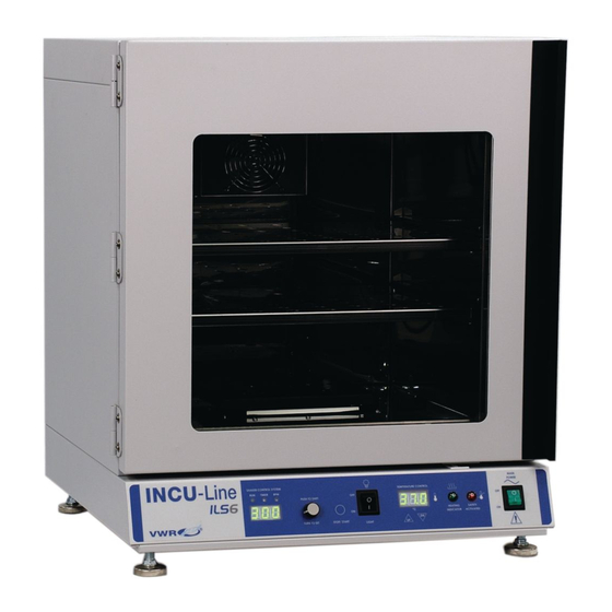
- Page 1 VWR INCU-Line Shake SHAKING INCUBATORS : ILS4, ILS6 ODELS INSTRUCTION MANUAL UROPEAN ATALOGUE UMBERS 444-0732 INCU-Line ILS 4 444-0733 INCU-Line ILS 6 ERSION : 09-18- 2014 SSUED...
- Page 2 Legal Address of Manufacturer United States Europe VWR International, LLC VWR International bvba 100 Matsonford Rd Researchpark Haasrode 2020 Radnor, PA 19087 Geldenaaksebaan 464 800-932-5000 B-3001 Leuven http://www.vwr.com + 32 16 385011 http://be.vwr.com Country of Origin United States...
-
Page 3: Table Des Matières
TABLE OF CONTENTS SECTION 1.0 INTRODUCTION SECTION 2.0 SYMBOLS AND CONVENTIONS SECTION 3.0 SPECIFICATIONS SECTION 4.0 SCOPE OF DELIVERY SECTION 5.0 INSTALLATION SECTION 6.0 CONTROLS OVERVIEW SECTION 7.0 OPERATION SECTION 8.0 CLEANING AND ROUTINE CARE SECTION 9.0 SERVICE AND TROUBLESHOOTING SECTION 10.0 PARTS LIST SECTION 11.0... -
Page 4: Introduction
Section INTRODUCTION The VWR Shaking incubators have been designed for general purpose incubations (up to 80ºC). These units are high performance shaking incubators for professional, industrial or educational use where the preparation or testing of materials is done at approximately atmospheric pressure and no flammable, volatile or combustible materials are being heated. -
Page 5: Symbols And Conventions
Section SYMBOLS AND CONVENTIONS ILS4 and ILS6 Your VWR incubator shakers use internationally accepted graphic symbols to help convey information to the user and to call the users attention to important safety precautions and guides for using this equipment. Indicates that user should consult manual further description or discussion. -
Page 6: Specifications
Section SPECIFICATIONS Temperature Range Ambient +5° to 80°C Temperature Uniformity ILS4 +0.2° @ 37°C ILS6 +0.25° @ 37°C Temperature Accuracy +0.2° Temperature Set / Display Digital Temperature Control Microprocessor Overtemperature Safety Independent, settable Door Inner – glass Outer - solid, heated Chamber Volume ILS4 0.048 cubic meters... -
Page 7: Scope Of Delivery
If any, the carrier will arrange for official inspection to substantiate your claim. Return Shipment: Save the shipping crate until you are sure all is well. If for any reason you must return the unit, contact VWR International, Inc. for authorization and supply the data plate information. -
Page 8: Installation
Section INSTALLATION Under normal circumstances this unit is intended for use indoors, at room temperatures between 5° and 40°C, at no greater than 80% Relative Humidity (at 25°C) and with a supply voltage that does not vary by more than 10%. Customer service should be contacted for operating conditions outside of these limits. - Page 9 appropriate to your application. DO NOT use chlorine-based bleaches or abrasives as this will damage the chamber interior. Regular periodic cleaning is required.
-
Page 10: Controls Overview
Section CONTROLS OVERVIEW From left to right SHAKER CONTROL SYSTEM: Run green signal light: lit when shaker is running. Time yellow signal light: lit when the shaker is set on time function. RPM yellow signal light: lit when the shaker is set on rpm function. Control Knob (Push to Shift / Turn to Set): by rotating the control knob right (+) or left (-) you can change the TIME or RPM. -
Page 11: Operation
Section OPERATION Main Power: Press the power switch to on. The unit will automatically detect supply frequency of 50 or 60Hz and displays F50 or F60. Then the display switches to show the set time and illuminates the time light. Set Main Temperature Control: The controller has a 3-digit display for displaying chamber temperature or set point information. - Page 12 Shaker Control System • Time signal light is on. By rotating the Control Knob right (+) or left (-) the set time can be selected from 30 sec to 99 min 50 sec : 99.5 ⇒ 99 min 50 sec 9.59 ⇒...
-
Page 13: Additional Operations
ADDITIONAL OPERATIONS • Door Open Switch: This switch senses when the incubator shaker door is open and sends a signal to microprocessor which causes the shaker to stop running as a safety measure. The timer will pause and re-start when door is closed. •... -
Page 14: Cleaning And Routine Care
If required, the chamber may be disinfected. Before using any type of disinfectant or cleaning agent in the shaking incubator, contact VWR Customer Service Department to ensure that the product will not damage the stainless steel interior of the shaking incubator. -
Page 15: Service And Troubleshooting
Section SERVICE AND TROUBLE-SHOOTING 9.1 Troubleshooting Guide Problem Possible Solution Oven will not power up or not Check power cord, outlet and unit circuit breaker heat Shaking platform will Check time set to Hld or a time setting operate Check that nothing is blocking shaker platform Press Stop / Start button Temperature too high Check set point and readjust if necessary... - Page 16 2/ If the sound gets worse, tap the other end of the shaft – avoiding touching the fan blade. 3/ If there is no change, call VWR Customer Service. 4/ If noise is from shaft or fan blade, realign shaft.
- Page 17 Other-1 Controller on at all times - "locked-up" 1/ Turn unit off and on to reset. 2/ If cannot change any condition on the front panel, call VWR Customer Service. Other-2 Front panel displays are all off Check for wire damage.
-
Page 18: Technical Service
Visit the VWR’s website at www.vwr.com for: • Complete technical service contact information • Access to VWR’s Online Catalogue, and information about accessories and related products • Additional product information and special offers Contact us For information or technical assistance contact your local VWR... -
Page 19: Parts List
Section PARTS LIST User replaceable accessories and spare parts Description Quantity Cat. No. SHELF FULL for ILS6 444-0831 SHELF FULL for ILS4 444-0832 SHELF HALF for ILS4 444-0833 ILS4 INCUBATOR STACKING ADAPTER 444-0913 Fuse 444-0828 Power Cord, EU 444-0827 Power Cord, UK 444-0829 Power Cord, Swiss 444-0830... -
Page 20: Warranty
(2) years from date of delivery. If a defect is present, VWR will, at its option and cost, repair, replace, or refund the purchase price of this product to the customer, provided it is returned during the warranty period. This warranty does not apply if the product has been damaged by accident, abuse, misuse, or misapplication, or from ordinary wear and tear. -
Page 21: Equipment Disposal
Section EQUIPMENT DISPOSAL This equipment is marked with the crossed out wheeled bin symbol to indicate that this equipment must not be disposed of with unsorted waste. Instead it's your responsibility to correctly dispose of your equipment at lifecycle -end by handling it over to an authorized facility for separate collection and recycling. - Page 23 VWR INCU-Line Shake SCHÜTTELINKUBATOREN : ILS4, ILS6 ODELLE BEDIENUNGSANLEITUNG UROPÄISCHE ATALOGNUMMERN 444-0732 INCU-Line ILS 4 444-0733 INCU-Line ILS 6 ERSION : 09-18-2014 USGABE...
- Page 24 Offizielle Anschrift des Herstellers Europa VWR International, LLC VWR International bvba 100 Matsonford Rd Researchpark Haasrode 2020 Radnor, PA 19087 Geldenaaksebaan 464 800-932-5000 B-3001 Leuven http://www.vwr.com + 32 16 385011 http://be.vwr.com Herkunftsland...
- Page 25 INHALTSVERZEICHNIS EINFÜHRUNG BSCHNITT SYMBOLE UND ZEICHEN BSCHNITT SPEZIFIKATIONEN BSCHNITT LIEFERUMFANG BSCHNITT INSTALLATION BSCHNITT ÜBERBLICK DES STEUERUNGSSYSTEMS BSCHNITT BETRIEB BSCHNITT REINIGUNG UND LAUFENDE INSTANDHALTUNG BSCHNITT Abschnitt 9.0 WARTUNG UND FEHLERBEHEBUNG Abschnitt 10.0 ERSATZTEILLISTE Abschnitt 11.0 GARANTIE Abschnitt 12.0 ALTGERÄTEENTSORGUNG...
-
Page 26: Einführung
Abschnitt EINFÜHRUNG Die Schüttelinkubatoren VWR wurden für allgemeine Inkubationszwecke (bis zu 80 ºC) konzipiert. Diese Geräte sind leistungsstarke Schüttelinkubatoren für professionelle, industrielle und bildungsbezogene Nutzung, wo die Vorbereitung oder Prüfung von Materialien ungefähr bei einem Atmosphärendruck und unter Ausschluss brennbarer, flüchtiger oder explosiver Materialien erfolgt. -
Page 27: Symbole Und Zeichen
Abschnitt SYMBOLE UND ZEICHEN Ihre Inkubationsschüttler VWR ILS4 und ILS6 verwenden international anerkannte grafische Symbole, um den Benutzern Informationen zu vermitteln und ihre Aufmerksamkeit auf wichtige Sicherheitsvorkehrungen und -vorgaben in Bezug auf den Einsatz dieser Ausrüstung zu lenken. Zeigt an, dass sich der Benutzer die Bedienungsanleitung für die weitere Beschreibung oder Diskussion heranziehen soll. -
Page 28: Spezifikationen
Abschnitt SPEZIFIKATIONEN Temperaturbereich Umgebung +5 bis 80 °C Temperaturgleichmäßigkeit ILS4 +0.2° @ 37°C ILS6 +0.25° @ 37°C Temperaturgenauigkeit +0.2° Temperatureinstellung / - digital anzeige Temperaturüberwachung Mikroprozessor Übertemperaturschutz Unabhängig, einstellbar Tür Innentür – verglast Außentür – fest, beheizt Kammerinhalt ILS4 0.048 Kubikmeter ILS6 0,078 Kubikmeter Außenkonstruktion... -
Page 29: Lieferumfang
Rücksendung: Behalten Sie die Transportkiste, bis Sie sicher sind, dass alles gut ist. Wenn Sie aus irgendeinem Grund das Gerät retournieren müssen, kontaktieren Sie VWR International, Inc. für die Autorisierung und geben Sie die Daten am Typenschild Accessoires: Stellen Sie sicher, dass alle im Lieferschein angegebenen Geräte mit dem Gerät mitgeliefert wurden. -
Page 30: Installation
Abschnitt INSTALLATION Unter normalen Umständen ist dieses Gerät für die Verwendung im Innenbereich bei Raumtemperaturen zwischen 5° und 40 °C und bei einer relativen Feuchtigkeit von maximal 80% (bei 25 °C) und für eine um höchstens 10% variierende Versorgungsspannung bestimmt. Bei Betriebsbedingungen, die über diese Werte hinausgehen, ist Kundenservice zu kontaktieren. - Page 31 Verschieben Schäden zu vermeiden. Reinigung: Die Kammer des Gerätes sollte vor der Verwendung gereinigt und desinfiziert werden. Entfernen Sie alle Innenteile und reinigen Sie gründlich mit einem für Ihre Anwendung geeigneten Desinfektionsmittel. Verwenden KEINE chlorhaltigen Bleichmittel oder Scheuermittel, da diese die Kammer Innenraum beschädigen.
-
Page 32: Überblick Des Steuerungssystems
Abschnitt ÜBERBLICK DES STEUERUNGSSYSTEMS Von links nach rechts STEUERUNGSSYSTEM: Run (Betrieb) – grünes Signallicht: leuchtet, wenn der Schüttler läuft. Time (Zeit) – gelbes Signallicht: leuchtet, wenn der Schüttler auf Zeit-Funktion eingestellt ist. RPM (Drehzahl) – gelbes Signallicht: leuchtet, wenn der Schüttler auf Drehzahl-Funktion eingestellt ist. - Page 33 Netzschalter: Der Hauptschalter ON / OFF steuert die Stromzufuhr zum Gerät. Er muss eingeschaltet werden (ON), bevor irgendwelche Systeme funktionsfähig sind. Der grüne Schalter leuchtet, wenn der Schalter in ON-Stellung steht.
-
Page 34: Betrieb
Abschnitt BETRIEB Hauptschalter: Drücken Sie den Netzschalter in ON-Stellung. Das Gerät erkennt automatisch die Netzfrequenz von 50 oder 60 Hz und zeigt F50 oder F60 an. Dann schaltet die Anzeige auf die eingestellte Zeit und das Zeit-Licht.geht an. Temperaturüberwachung: Das Steuersystem verfügt über ein 3-stelliges Display zur Anzeige der Kammertemperatur oder den Sollwert. - Page 35 kleinsten Teile auf seiner Skala über den Punkt hinaus, wo die Sicherheitsleuchte ausging. Dadurch wird der Sicherheitsthermostat bei etwa 1 °C über Haupt-Sollwert eingestellt. Steuerungssystem • Die Zeit-Signalleuchte leuchtet. Durch Drehen des Drehknopfes nach rechts (+) oder links (- ) kann die eingestellte Zeit von 30 Sek. bis 99 Min. 50 Sek. gewählt werden: 99.5 ⇒...
- Page 36 • Wenn Sie den Drehzahl-Sollwert beim Schütteln sehen möchten, drehen Sie den Drehregler für EINEN KLICK rechts (+) oder links (-). Die Drehzahl-Signalleuchte blinkt dann für 2 Sekunden und auf dem Display wird die eingestellte Drehzahl angezeigt. Nach 2 Sekunden werden die Drehzahl und die Leuchte nicht mehr blinken. HINWEIS: Der Schüttler muss sich in dem Drehzahl-Modus befinden –...
-
Page 37: Reinigung Instandhaltung
Tuch durchgeführt werden. Falls erforderlich, kann die Kammer desinfiziert werden. Bevor Sie irgendein Desinfektionsmittel oder Reinigungsmittel im Schüttelinkubator verwenden, kontaktieren Sie den VWR-Kundendienst, um sicherzustellen, dass das Produkt die Edelstahl-Innenraum des Schüttelinkubators.nicht beschädigt. Nach der Reinigung des Schüttelinkubators spülen Sie die gereinigte Fläche ausschließlich unter Einsatz... -
Page 38: Wartung Und Fehlerbehebung
Abschnitt WARTUNG UND FEHLERBEHEBUNG 9.1 Fehlersuchanleitung Problem Mögliche Lösung Ofen lässt sich nicht Überprüfen Sie das Netzkabel, die Steckdose und den einschalten oder heizt nicht Leistungsschalter des Gerätes. Die Schüttelplattform arbeitet nicht. Prüfen eingestellte Zeit oder eine Zeiteinstellung Prüfen, ob kein Gegenstand die Schüttelplattform blockiert. - Page 39 Die Stromquelle prüfen. Sicherungen prüfen. Schüttler Stillstand Den Antrieb ausschalten und neu starten. gebracht – Meldung <Er1> Meldung <Er2> VWR-Servicedienst kontaktieren. Meldung <Er3> VWR-Servicedienst kontaktieren. Meldung <Er4> VWR-Servicedienst kontaktieren. MECHANISCHER TEIL Mech-1 Tür nicht abgedichtet 1/ Den physischen Zustand der Dichtung prüfen.
- Page 40 Steuersystem jederzeit ges-1 “geschlossen” ("locked-up") 1/ Das Gerät ausschalten, um einen Reset auszuführen. 2/ Wenn es an der Frontplatte keine Änderung gibt, kontaktieren Sie bitte den VWR-Servicedienst. Sonsti Alle Anzeigen auf der ges-2 Frontplatte sind ausgeschaltet Auf Kabelschäden überprüfen. Sonsti Gerät oder...
-
Page 41: Technischer Kundendienst
• Alle Kontaktdaten des technischen Kundendienstes • VWR Online-Katalog sowie Informationen über Zubehör und zugehörige Produkte • Weiterführende Produktinformationen und Sonderangebote Kontakt Wenn Sie Informationen oder technische Unterstützung benötigen, wenden Sie sich an Ihr VWR Vertriebszentrum oder besuchen Sie unsere Website unter www.vwr.com... -
Page 42: Ersatzteilliste
Abschnitt ERSATZTEILLISTE Vom Benutzer austauschbares Zubehör und Ersatzteile Beschreibung Anzahl Kat.-Nr. SHELF FULL for ILS6 444-0831 SHELF FULL for ILS4 444-0832 SHELF HALF for ILS4 444-0833 ILS4 Schüttelinkubatoren Stapeladapter 444-0913 Fuse 444-0828 Power Cord, EU 444-0827 Power Cord, UK 444-0829 Power Cord, Swiss 444-0830... -
Page 43: Garantie
VWR International garantierte, dass dieses Produkt frei von Mängeln in Bezug auf Material und Verarbeitung für einen Zeitraum von zwei (2) Jahre ab dem Datum der Lieferung ist. Wenn ein Mangel vorliegt, wird VWR nach eigenem Ermessen und auf eigene Kosten das Produkt reparieren, ersetzen oder dem Kunden den Kaufpreis des Produktes erstatten, vorausgesetzt, dass es während der Garantiezeit zurückgegeben... -
Page 44: Altgeräteentsorgung
Abschnitt ALTGERÄTEENTSORGUNG Dieses Gerät ist mit der durchgestrichenen Mülltonne gekennzeichnet, um anzuzeigen, dass das Gerät nicht mit dem unsortierten Hausmüll entsorgt werden darf. Stattdessen liegt es in Ihrer Verantwortung, Ihr Gerät am Ende des Lebenszyklus zur Entsorgung an den autorisierten Entsorger für die getrennte Sammlung und das Recycling zu übergeben. -
Page 46: Vwr Incu-Line Shake Incubateurs Agitateurs
VWR INCU-Line Shake INCUBATEURS AGITATEURS : ILS4, ILS6 MODÈLES MODE D’EMPLOI EFERENCES DE CATALOGUE EUROPEEN 444-0732 INCU-Line ILS 4 444-0733 INCU-Line ILS 6 ERSION É : 09-18- 2014 MIS LE... -
Page 47: Adresse Du Siège Légale Du Fabricant
Adresse du siège légale du fabricant États-Unis Europe VWR International LLC VWR International bvba 100 Matsonford Rd Researchpark Haasrode 2020 Radnor, PA 19087 Geldenaaksebaan 464 800-932-5000 B-3001 Leuven http://www.vwr.com + 32 16 385011 http://be.vwr.com Pays de provenance États-Unis... - Page 48 TABLE DES MATIÈRES CHAPITRE 1.0 INTRODUCTION CHAPITRE 2.0 SYMBOLES ET CONVENTIONS CHAPITRE 3.0 CARACTÉRISTIQUES CHAPITRE 4.0 CONTENU DE LA LIVRAISON CHAPITRE 5.0 INSTALLATION CHAPITRE 6.0 REVUE DE CONTRÔLES CHAPITRE 7.0 FONCTIONNEMENT CHAPITRE 8.0 NETTOYAGE ET ENTRETIEN CHAPITRE 9.0 SERVICE ET DÉPANNAGE CHAPITRE 10.0 LISTE DES PIÈCES CHAPITRE 11.0...
-
Page 49: Chapitre 1.0 Introduction
Chapitre INTRODUCTION Les incubateurs agitateurs VWR ont été conçus pour l’incubation à usage général (jusqu'à 80ºC). Ces unités sont des incubateurs agitateurs de haute performance pour un usage professionnel, industriel ou éducatif où soit la préparation soit les tests des matériaux se fait /se font/ à pression proche de l’atmosphérique et quand les matériaux inflammables, volatils ou combustibles sont réchauffés. -
Page 50: Chapitre 2.0 Symboles Et Conventions
Chapitre SYMBOLES ET CONVENTIONS Les incubateurs agitateurs ILS4 et ILS6 VWR utilisent des symboles graphiques internationalement reconnus qui transmettent des informations à l'utilisateur et attirent son attention en cas de précautions. Les symboles fournissent les guides de sécurité importants pour l'utilisation de cet équipement. -
Page 51: Chapitre 3.0 Caractéristiques
Chapitre CARACTÉRISTIQUES Plage de température Ambiante +5° à 80°C Uniformité de la température ILS4 +0,2° @ 37°C ILS6 +0,25° @ 37°C Précision de la température +0,2° Réglage/affichage de la température Numérique Contrôle de la température Microprocesseur Protection de surchauffe Indépendant, réglable Porte Intérieure –... -
Page 52: Chapitre 4.0 Contenu De La Livraison
Renvoie : Conservez le bordereau de livraison jusqu'à ce que vous soyez sûr que tout est conforme. Si pour une raison quelconque, vous devez retourner l'unité, contactez la société VWR International Inc. pour l'autorisation en indiquant les informations se trouvant sur la plaque signalétique. -
Page 53: Chapitre 5.0 Installation
Chapitre INSTALLATION Dans des conditions normales, cette unité est conçue pour une utilisation à l’intérieur, à des températures ambiantes comprises entre 5° et 40°C, à une humidité relative ne dépassant pas 80% (à 25°C) et avec une tension d'alimentation qui ne varie pas de plus de 10%. Contactez le service de la clientèle en cas des conditions de fonctionnement en dehors de ses limites. -
Page 54: Chapitre 6.0 Revue De Contrôles
Chapitre REVUE DE CONTRÔLES De gauche à droite SYSTÈME DE CONTROL DE L’AGITATEUR : Marche (run)- voyant vert : allumé quand l’agitateur est en marche. Temps (timer)- voyant jaune : allumé quand l’agitateur est fixé en fonction de temps. RPM - voyant jaune : allumé quand l’agitateur est fixé en fonction rpm. Bouton de commande (Appuyez pour sélectionner/Tourner pour régler/ajuster) : en tournant le bouton droit de contrôle (+) ou gauche (-) vous pouvez changer le temps ou RPM. -
Page 55: Chapitre 7.0 Fonctionnement
Chapitre FONCTIONNEMENT Alimentation principale : Mettez l'interrupteur d'alimentation sur ON. L'appareil détecte automatiquement la fréquence d'alimentation de 50 ou 60 Hz et affiche F50 ou F60. Ensuite, l'affichage change pour afficher le temps réglé et allume le voyant de contrôle du temps. Commande principale de la température : L'automate dispose d'un afficheur à... -
Page 56: Système De Commande De L'agitateur
dans le sens antihoraire, jusqu'à ce que le voyant de sécurité s'allume. Ensuite, tournez le thermostat dans le sens horaire jusqu'à ce que le voyant de sécurité s’éteigne. Puis tournez le thermostat dans le sens horaire sur deux (2) de ses plus petites divisions sur l’ampleur jusqu’à... -
Page 57: Fonctions Supplémentaires
l’agitateur s'arrête complètement la vitesse et le temps réglés reviennent aux dernières valeurs programmées. FONCTIONS SUPPLÉMENTAIRES • Interrupteur de porte ouverte : Cet interrupteur détecte l’ouverture de la porte de l’agitateur et envoie un signal au microprocesseur qui entraîne l’arrêt de l’agitateur comme une mesure de sécurité. -
Page 58: Chapitre 8.0 Nettoyage Et Entretien
Le nettoyage peut être effectué avec un chiffon doux et humide. Si nécessaire, la chambre peut être désinfectée. Avant d'utiliser tout type de désinfectant ou agent de nettoyage dans l'incubateur agitateur, contactez le service de clientèle VWR pour s'assurer que le produit n’endommage pas l'intérieur de l’incubateur agitateur en acier inoxydable. -
Page 59: Chapitre 9.0 Service Et Dépannage
Chapitre SERVICE ET DÉPANNAGE 9.1 Guide de dépannage Problème Solution possible Le four ne s'allume pas ou il n’y a Vérifiez le câble d'alimentation, la sortie pas de chaleur. et le disjoncteur Le plateau d'agitation ne fonctionne Vérifiez le temps réglé à Hld ou le réglage de pas. -
Page 60: Mécanique
Contrôlez la source d’alimentation. ne s'allume pas. Contrôlez les fusibles. L’agitateur affiche - Message <Er1> Eteignez l’unité d’alimentation et redémarrez (restart). Message <Er2> Contactez le service VWR. Message <Er3> Contactez le service VWR. Message <Er4> Contactez le service VWR. MÉCANIQUE Méc-1... - Page 61 Autre-1 Le contrôleur est tout le temps – « verrouillé » 1/ Éteignez l’unité et réinitialisez. 2/ Si vous n’arrivez pas à changer le fonctionnement à l’aide du panneau frontal, contactez le service VWR. Autre -2 Tous les afficheurs du panneau frontal sont éteints Contrôler le câble d’alimentation.
-
Page 62: Service Technique
: • Coordonnées complètes du service technique. • Accès au catalogue en ligne de VWR et à des informations sur les accessoires et produits connexes. • Informations supplémentaires sur les produits et les offres spéciales. Contactez-nous Pour plus d'informations ou une assistance technique, contactez votre... -
Page 63: Chapitre 10.0 Liste Des Pièces
Chapitre LISTE DES PIÈCES Accessoires et pièces de rechange Description Quantité N° de réf. SHELF FULL for ILS6 444-0831 SHELF FULL for ILS4 444-0832 SHELF HALF for ILS4 444-0833 ILS4 INCUBATEUR STACKING ADAPTER 444-0913 Fuse 444-0828 Power Cord, EU 444-0827 Power Cord, UK 444-0829 Power Cord, Swiss... -
Page 64: Chapitre 11.0 Garantie
(2) ans à compter de la date de sa livraison. Si un défaut est présent, VWR, à son gré et à ses frais, réparera, remplacera ou remboursera le prix d'achat de ce produit pour le client, à condition qu'il soit retourné... -
Page 65: Chapitre 12.0 Recyclage Ou Élimination D'appareils Usagés
Chapitre RECYCLAGE OU ÉLIMINATION D'APPAREILS USAGÉS Cet équipement comporte le symbole de la poubelle barrée qui indique cet équipement ne doit pas être jeté avec les déchets non triés. Au contraire, il est de votre responsabilité d'éliminer correctement votre équipement à la fin du cycle de vie en le transmettant à... - Page 67 VWR INCU-Line Shake INCUBADORA AGITADORA VWR DE LABORATORIO : ILS4, ILS6 ODELOS MANUAL DE INSTRUCCIONES NÚMEROS EUROPEOS DE CATÁLOGO 444-0732 INCU-Line ILS 4 444-0733 INCU-Line ILS 6 ERSIÓN : 09-18- 2014 EDICIÓN Nota de traductora: llamando también por ciertas empresas como agitador de incubación.
- Page 68 Dirección de la empresa productora y su sede legal Estados Unidos Europa VWR International LLC VWR International bvba 100 Matsonford Rd Researchpark Haasrode 2020 Radnor, PA 19087 Geldenaaksebaan 464 800-932-5000 B-3001 Leuven http://www.vwr.com + 32 16 385011 http://be.vwr.com País de origen...
- Page 69 ÍNDICE SECCIÓN 1.0 INTRODUCCIÓN SECCIÓN 2.0 SÍMBOLOS Y TIPOGRÁFICOS CONVENCIONALES SECCIÓN 3.0 ESPECIFICACIÓN SECCIÓN 4.0 ALCANCE DE SUMINISTRO SECCIÓN 5.0 INSTALACIÓN SECCIÓN 6.0 IDENTIFICACIÓN DE CONTROLES SECCIÓN 7.0 MANEJO DE INCUBADORA SECCIÓN 8.0 MANTENIMIENTO Y LIMPIEZA SECCIÓN 9.0 SERVICIO TÉCNICO Y DIAGNÓSTICOS SECCIÓN 10.0 LISTADO DE PIEZAS DE RECAMBIO SECCIÓN 11.0...
- Page 70 Sección INTRODUCCIÓN Las incubadoras agitadoras de laboratorio VWR han sido diseñadas con el objeto general de incubación (hasta 80ºC). Estas unidades son incubadoras de alto rendimiento para el uso profesional, industrial o educativo donde la preparación o pruebas de materiales se efectúan en condiciones aproximadas a la presión atmosférica y donde no se calientan materiales volátiles o combustibles.
- Page 71 SÍMBOLOS Y TIPOGRÁFICOS CONVENCIONALES Las incubadoras agitadoras VWR y ILS6 utilizan señales gráficas aceptadas en el mundo entero para ayudar al usuario a obtener la información indispensable, para llamar su atención sobre precauciones importantes de seguridad y para guiarle en el manejo del aparato.
- Page 72 5. Prueba de estabilidad: Pruebe el aparato para asegurase que esté estable. 6. Unidad ILS6 embalada por separado. No ponga una unidad encima de la otra.
- Page 73 Sección ESPECIFICACIÓN Rango de temperatura Ambiente +5° hasta 80°C Uniformidad de temperatura ILS4 +0,2° @ 37°C ILS6 +0,25° @ 37°C Exactitud de temperatura +0,2° Programación de temperatura / Digital display Control de temperatura Microprocesador Seguridad de Independiente, estable sobrecalentamiento Puerta Interior –...
-
Page 74: Alcance De Suministro
4.3 Devolución del envío: Guarda el embalaje hasta asegurarse que todo esté bien. Si por cualquier razón tiene que devolver el aparato, contacte con VWR International Inc para recibir la autorización y pase la información de datos de la placa de matrícula. - Page 75 Sección INSTALACIÓN En circunstancias normales este aparato está diseñado para su utilización en interiores a la temperatura entre 5° y 40°C, pero no más alta de 80% de la humedad relativa (a 25°C) y con el suministro del voltaje que no varía más de 10%. Puede contactar con el servicio de atención al cliente en caso de que dichos límites estén diferentes.
- Page 76 Sección IDENTIFICACIÓN DE CONTROLES De izquierda hacía derecha. SISTEMA DE CONTROL DE AGITACIÓN: Run (marcha): luz verde, incubadora agitadora está en marcha. Timer (tiempo): luz amarilla, aparece cuando la incubadora agitadora está programada por un tiempo. RPM luz amarilla: cuando está programada la función RPM. Botón de control (pulse para selección/ gire para ajustes): al girar el botón de control a la derecha (+) o a la izquierda (-) puede cambiar TIEMPO (TIME) o RPM.
- Page 77 Sección FUNCIONAMIENTO Alimentación principal: Ponga la tecla de alimentación en posición ON. El aparato detectará automáticamente frecuencia de alimentación de 50 o 60 Hz y aparecerá F50 o F60. En el display aparecerán las luces de programación de tiempo. Programación de control de temperatura: El regulador tiene 3 displays digitales para mostrar la temperatura de la cámara o la información de punto de programación.
- Page 78 sentido de las agujas del reloj dos (2) de sus divisiones más pequeñas en la escala hasta las luces de seguridad estén apagadas. Esto va a programar el termostato de seguridad a 1 C encima de la temperatura principal del punto de programación.
-
Page 79: Operaciones Adicionales
OPERACIONES ADICIONALES • La luz de señal de puerta abierta: Aparece cuando la puerta del agitador de incubadora está abierta y envía la señal a microprocesador para provocar que el agitador deje de funcionar como medida de seguridad. El timer parará y de nuevo se pondrá en marcha cuando la puerta esté cerrada. •... -
Page 80: Mantenimiento Y Limpieza
Antes de utilizar un desinfectante o líquido de limpiar para incubadora agitadora contacte con la oficina de atención al cliente de VWR para asegurarse que el producto no va a deteriorar acero inoxidable del interior de la incubadora. -
Page 81: Guía De Problemas
Sección Servicio técnico y diagnósticos 9.1 Guía de problemas Problema Posible solución El horno no funciona Compruebe el cable de alimentación, el enchufe o no calienta. y el interruptor. La plataforma del agitador Compruebe la programación de TIME (tiempo) o Hld. no funciona. - Page 82 Compruebe los fusibles. El agitador está bloqueado. Desconecte el aparato del suministro eléctrico, - Mensaje <Er1> reinícielo (restart). Mensaje <Er2> Contacte el servicio VWR. Mensaje <Er3> Contacte el servicio VWR. Mensaje <Er4> Contacte el servicio VWR. MECÁNICO Mec-1 Puerta no hermética.
- Page 83 “cerrado”/"locked-up". 1/ Apague la unidad y vuelva a encenderla. 2/ Si no se puede cambiar condiciones del panel frontal llame al servicio de atención al cliente de VWR. Otro-2 Panel frontal del display está apagado. Compruebe si no hay daños en cable de alimentación.
-
Page 84: Servicio Técnico
• Obtener los contactos del servicio técnico • Acceder al Catálogo en línea de VWR y obtener información acerca de accesorios y productos relacionados • Información adicional sobre productos y ofertas especiales Contacto Para obtener más información o asistencia técnica póngase en contacto con... -
Page 85: Accesorios Y Piezas De Recambio
Sección LISTADO DE PIEZAS DE RECAMBIO Accesorios y piezas de recambio Descripción Cantidad Número de catálogo. SHELF FULL for ILS6 444-0831 SHELF FULL for ILS4 444-0832 SHELF HALF for ILS4 444-0833 ILS4 INCUBADORA ESTIBACIÓN ADAPTADOR 444-0913 Fuse 444-0828 Power Cord, EU 444-0827 Power Cord, UK 444-0829... - Page 86 La garantía VWR incluye la reparación, la reposición o el cambio del producto y/o de los componentes sin cargo alguno para el cliente, incluyendo la mano de obra, así...
- Page 87 Sección ELIMINACIÓN DE RESIDUOS DE EQUIPOS Este equipo está marcado con un canasto de ruedas cruzado para indicar que el aparato no debe eliminarse utilizando los contenedores tradicionales para residuos domésticos. Es su responsabilidad de entrar su incubadora en un centro especial de recogida. Es también su responsabilidad de descontaminar el aparato en caso de la contaminación biológica, química y/o radiológica para evitar las consecuencias negativas para la salud de las personas relativas al uso y al reciclaje del aparato.
- Page 89 VWR INCU-Line Shake INCUBATORI AGITANTI : ILS4, ILS6 ODELLI MANUALE D’USO UMERI DEL ATALOGO UROPEO 444-0732 INCU-Line ILS 4 444-0733 INCU-Line ILS 6 ERSIONE : 09-18-2014 UBBLICATA...
- Page 90 Indirizzo e sede legale di fabbricante Stati Uniti Europa VWR International LLC VWR International bvba 100 Matsonford Rd Researchpark Haasrode 2020 Radnor, PA 19087 Geldenaaksebaan 464 800-932-5000 B-3001 Leuven http://www.vwr.com + 32 16 385011 http://be.vwr.com Paese di origine Stati Uniti...
- Page 91 TABELLA CONTENUTI SEZIONE 1.0 INTRODUZIONE SEZIONE 2.0 SIMBOLI E CONVENZIONI TIPOGRAFICHE SEZIONE 3.0 DATI TECNICI SEZIONE 4.0 SCOPO DI CONSEGNA SEZIONE 5.0 INSTALLAZIONE SEZIONE 6.0 CONTROLLI SEZIONE 7.0 FUNZIONAMENTO SEZIONE 8.0 PULIZIA E MANUTENZIONE ORDINARIA SEZIONE 9.0 ASSISTENZA E SOLUZIONE DEI PROBLEMI SEZIONE 10.0 LISTA RICAMBI SEZIONE 11.0...
- Page 92 Sezione INTRODUZIONE Gli incubatori agitanti VWR nascono come incubatori generici (fino a 80ºC). Questi dispositivi sono incubatori agitanti di alta qualità per uso professionale, industriale o didattico, dove la preparazione o i test dei materiali vengono eseguiti a pressione approssimativamente atmosferica e senza il riscaldamento di materiali infiammabili, volatili o combustibili.
-
Page 93: Precauzioni Di Sicurezza
Sezione SIMBOLI E CONVENZIONI TIPOGRAFICHE ILS4 e ILS6 Gli incubatori agitanti VWR sfruttano i simboli grafici internazionali per trasmettere le informazioni all’utente, focalizzare la sua attenzione sulle precauzioni di sicurezza e istruzioni d’uso importanti. indica che l’utente deve consultare ulteriore descrizione o discussione nel manuale. -
Page 94: Dati Tecnici
Sezione DATI TECNICI Campo temperatura Ambiente da +5° a 80°C Uniformità termica ILS4 ±0,2° @ 37°C ILS6 ±0,25° @ 37°C Precisione temperatura +0,2° Impostazione/display temperatura Digitale Controllo temperatura Microprocessore Sicurezza surriscaldamento Indipendente, impostabile Porta Interna – vetro Esterna – solida, riscaldata Volume camera ILS4 0,048 metri cubi... - Page 95 Rispedizione: mantenere la cassa di trasporto finché non si è sicuri che tutto vada bene. Se per qualsiasi ragione il dispositivo deve essere rispedito, contattare VWR International Inc. per l’autorizzazione e fornire i dati di targa. Accessori: verificare che tutti gli accessori indicati nel packing list sono compresi nella fornitura.
- Page 96 Sezione INSTALLAZIONE Nelle condizioni normali questo dispositivo è previsto per uso in ambienti chiusi, nella temperatura da 5° a 40°C, umidità relativa non superiore a 80% (a 25°C), e la variazione di tensione di alimentazione non superiore a 10%. Nel caso delle condizioni di lavoro al di fuori di questi limiti, è...
- Page 97 Sezione CONTROLLI Da sinistra a destra SISTEMA DI CONTROLLO AGITATORE: Spia verde Run: accesa quando il dispositivo è in funzione. Spia gialla Timer: accesa quando il dispositivo è impostato in modalità TEMPO. Spia gialla RPM: accesa quando il dispositivo è impostato in modalità RPM. Manopola di controllo (premere per selezionare/ girare per impostare): ruotando la manopola di controllo a destra (+) o a sinistra (-) si imposta modalità...
- Page 98 Sezione FUNZIONAMENTO Alimentazione generale: mettere l’interruttore di potenza in posizione ON. Il dispositivo rileva automaticamente la frequenza di alimentazione di 50 o 60 Hz visualizzando rispettivamente F50 o F60. Successivamente il display visualizza l’impostazione del tempo e si accende la spia del tempo. Impostazione del controllo di temperature generale: il regolatore è...
- Page 99 Sistema di controllo agitatore • Spia di controllo tempo è accesa. Ruotando la manopola di controllo a destra (+) o sinistra (-) si può selezionare l’impostazione del tempo da 30 sec a 99 min 50 s: 99,5 ⇒ 99 min 50 s 9,59 ⇒...
- Page 100 OPERAZIONI SUPPLEMENTARI • Interruttore apertura porta: questo interruttore sente quando la porta dell’incubatore è aperta e manda il segnale al microprocessore che provvede a fermare l’agitatore come misura di sicurezza. Il timer mette in pausa e fa ripartire dopo che la porta sia chiusa. •...
-
Page 101: Pulizia E Manutenzione Ordinaria
Se necessario, la camera può essere disinfettata. Prima di usare qualsiasi tipo di disinfettante o detergente, contattare l’Assistenza Clienti VWR per assicurarsi che il prodotto che si vuole usare non danneggi l’acciaio inox all’interno dell’incubatore agitante. Dopo la pulizia dell’incubatore, risciacquare la superficie pulita con un panno umido, usando solo dell’acqua. -
Page 102: Guida Alla Soluzione Dei Problemi
Sezione ASSISTENZA E SOLUZIONE DEI PROBLEMI 9.1 Guida alla soluzione dei problemi Problema Possibile soluzione Forno non è alimentato o non Controllare il cavo di alimentazione, presa elettrica riscalda. e l’interruttore del circuito. Piattaforma agitante Controllare valore impostato a Hld o impostazioni di tempo. non funziona. - Page 103 2/ Se il rumore peggiora, battere l’albero dall’altro lato – evitando di toccare la pala del ventilatore. 3/ Se non cambia niente, chiamare l’assistenza clienti VWR. 4/ Se il rumore proviene dall’albero o dalla lama del ventilatore, riallineare l’albero.
-
Page 104: Altri Problemi
– “bloccato” ("locked-up"). 1/ Spegnere e riaccendere il dispositivo per resettarlo. 2/ Se non è possibile cambiare nessuna condizione sul pannello frontale, chiamare l’Assistenza Clienti VWR. Altro-2 I display sul pannello frontale sono tutti spenti. Controllare che il cavo non sia danneggiato. -
Page 105: Assistenza Tecnica
• Informazioni complete sui contatti dell'Assistenza tecnica • Accesso al catalogo on-line VWR e ad ogni altra informazione relativa agli accessori e ai prodotti collegati • Ulteriori informazioni sui prodotti e sulle promozioni Contatti Per informazioni o assistenza tecnica, contattare i nostri uffici VWR o visitare il sito. -
Page 106: Lista Ricambi
Sezione LISTA RICAMBI Accessori sostituibili dall’utente e parti di ricambio Descrizione Quantità N. di catalogo SHELF FULL for ILS6 444-0831 SHELF FULL for ILS4 444-0832 SHELF HALF for ILS4 444-0833 ILS4 INCUBATORE IMPILAMENTO ADATTATORE 444-0913 Fuse 444-0828 Power Cord, EU 444-0827 Power Cord, UK 444-0829... - Page 107 (2) anni dalla data di consegna. Nel caso si riscontrasse un difetto, la VWR, a suo parere e a sue spese, provvederà a riparare, sostituire o rimborsare le spese sostenute dal cliente per l’acquisto di un pezzo, a condizione che questo sia ritornato nel periodo di garanzia.
-
Page 108: Smaltimento Del Dispositivo
Sezione SMALTIMENTO DEL DISPOSITIVO Questo dispositivo è marcato con il simbolo che rappresenta il bidone con la croce sopra, per indicare che il dispositivo non può essere smaltito con i rifiuti non selezionati (normali rifiuti solidi urbani). Voi siete responsabili per il corretto smaltimento del dispositivo alla fine del ciclo della sua vita e dovete trasmetterlo all’ente autorizzata per la raccolta differenziata e riciclaggio.