Table des Matières

Publicité

Les langues disponibles
  • FR

Les langues disponibles

Liens rapides

_ Betriebsanleitung
_ User Manual
_ Mode d'emploi
_ Instruzioni d'uso
_ Modo de empleo
_ Deutsch
3 - 27
_ English
28 - 51
_ Français
52 - 77
_ Italiano
78 - 102
_ Español
103 - 128

Publicité

Table des Matières
loading

Sommaire des Matières pour Amann Girrbach Ceramill Map400

  • Page 1 _ Betriebsanleitung _ User Manual _ Mode d‘emploi _ Instruzioni d‘uso _ Modo de empleo _ Deutsch 3 - 27 _ English 28 - 51 _ Français 52 - 77 _ Italiano 78 - 102 _ Español 103 - 128...
  • Page 3: Table Des Matières

    CE-Konformitätserklärung ..6 Bauteile und Schnittstellen ..7 4.4.1 Ceramill Map400 ....7 Störungen, Reparaturen und 4.4.2 Ceramill Transferkit .
  • Page 4: Symbolerklärung

    S Y M B O L E R K L Ä R U N G Symbolerklärung Weitere Symbole in der Anleitung Warnhinweise Symbol Bedeutung ▷ Punkt einer Handlungsbeschreibung Warnhinweise im Text werden mit einem farbig hinterlegten Warndreieck gekenn- Punkt einer Liste zeichnet und umrandet.
  • Page 5: Allgemeine Sicherheitshinweise

    A L L G E M E I N E S I C H E R H E I T S H I N W E I S E Allgemeine Sicherheits- Geeignetes Personal hinweise HINWEIS: Bei der Aufstellung, Inbetriebnahme und Benut- Das Gerät darf nur von geschultem Fachperso- zung des Geräts sind stets die folgenden Sicher- nal in Betrieb genommen und bedient werden.
  • Page 6: Angaben Zum Gerät

    A N G A B E N Z U M G E R Ä T Angaben zum Gerät Lieferumfang des Komplett- Bestimmungsgemäßer Gebrauch systems (inkl. Virtueller Artikula- Der Ceramill Map400 ist ein PC-gesteuerter 3D- tor) Scanner zur Erfassung von dentalen Zahn- modellen. _ Scanner Ceramill Map400 (179140) ▪...
  • Page 7: Bauteile Und Schnittstellen

    A N G A B E N Z U M G E R Ä T Bauteile und Schnittstellen 4.4.2 Ceramill Transferkit 4.4.1 Ceramill Map400 Bild 1 Geräteübersicht Frontseite 1 Artex Scan Base Plate 2 Bedientaste Bild 3 A Scanaufbau für Modelle ohne Artikulations- sockel B Scanaufbau für Modelle mit Artikulationssockel...
  • Page 8: 4.4.3 Pc Typ T3500

    A N G A B E N Z U M G E R Ä T Die Artex Scan Base Plate befindet sich fest im 4.4.3 PC Typ T3500 Scanner Ceramill Map400. Auf diese werden nach Bedarf die Distanzplatten 1 7 und 2 6 und die Fixierplatte mit Klemme 5 geschraubt. Welche Distanzplatten und welche Schraube 3 genutzt werden, hängt von der Höhe des zu scannenden...
  • Page 9: Installation

    I N S T A L L A T I O N Installation ▷ Das weiße DVI-Kabel (digital) am Monitor sowie Transport am digitalen Anschluss des PC anschließen ▷ Das Gerät mit zwei Personen an der Boden- ▷ Maus und Tastatur am PC anschließen. platte anheben und transportieren.
  • Page 10: Installation Der Software Ceramill Mind Und Ceramill Map

    I N S T A L L A T I O N ▷ Das Netzkabel an den Netzanschluss des Scan- 5.4.2 Installation der Software Ceramill Mind und Ceramill Map ners sowie an eine Netzsteckdose anschließen. Die PCs werden werkseitig mit einer Grundinstal- Freischalten von Zusatzmodulen lationen versehen.
  • Page 11: Installation Des Anti-Viren

    I N S T A L L A T I O N Achskalibrierung Gleichschaltung Artex Fixator Der Scanner Ceramill Map400 muss nach dem Die Gleichschaltung des Fixators mit dem Aufstellen und Anschluss an den PC mithilfe des Splitexschlüssel sollte in regelmäßigen mitgelieferten Kalibriermodells kalibriert werden.
  • Page 12: Registrierung Artex Fixator

    I N S T A L L A T I O N ▷ Fixator bis zum Anschlag zuklappen und mit HINWEIS: seitlicher Schraube 6 fixieren. ▷ Klebeverbindung gemäß Kleberanleitung aus- Fehlerhafte Registrierung des Fixators! ▷ Kiefermodelle grundsätzlich mit Gipssockel in härten lassen.
  • Page 13 I N S T A L L A T I O N ▷ Ceramill Mind Database starten. ▷ Einen fiktiven Patientenfall mit Indikationen in Ober- & Unterkiefer anlegen (z. B. Käppchen im OK und Antagonist im UK) ▷ Als Antagonistentyp Artex CR auswählen.
  • Page 14 I N S T A L L A T I O N ▷ Distanzplattenzahl auswählen. ▷ Im Bereich Scantyp Komplettkiefer selektieren. Bild 9 ▷ Über den Button Weiter den 3D-Scan starten.
  • Page 15 I N S T A L L A T I O N ▷ Das Scanergebnis überprüfen und ggf. nachscannen. Bild 10 ▷ Den Anweisungen der Software folgen. ▷ Den Oberkiefer entnehmen. ▷ Den Unterkiefer im Messbereich unter Verwendung der notwendigen Distanzplatte (0, 1, 2 oder 1+2) im Scanner positionieren (siehe Kapitel 6.2).
  • Page 16 ▷ Anschließend die seitliche Schraube des Fixators anziehen. ▷ Den Fixator in den Scanner einsetzen. Die Klemme der Fixierplatte muss in das Unterteil des Fixators greifen Bild 11 Fixator im Ceramill Map400 1 Artex Fixator 5 Artex Scan Base Plate...
  • Page 17 I N S T A L L A T I O N ▷ Mit dem Button Weiter den Vestibulärscan starten. ▷ Den Anweisungen der Software folgen. ▷ Die Software verlangt für die notwendige Registrierung des Fixators die 3-Punkt-Zuordnung. ▷ Mit bestätigen.
  • Page 18 I N S T A L L A T I O N ▷ Drei Punkte im Unterkiefer (auf die Modellmarkierungen) setzen. Entf/Del Mit der Taste kann der zuletzt gesetzte Punkt wieder gelöscht werden. Bild 12...
  • Page 19 I N S T A L L A T I O N ▷ Mit der Leertaste auf den Vestibulärscan umschalten. Bild 13...
  • Page 20 I N S T A L L A T I O N ▷ Dort in gleicher Reihenfolge drei Punkte an die gleichen Markierungen setzen. Der Unterkiefer wird zugeordnet. Artikulation Falls die Zuordnung falsch erstellt wurde, kann sie über die Funktion wiederholt werden.
  • Page 21 I N S T A L L A T I O N ▷ Mit dem Button Weiter die Oberkiefer-Zuordnung starten. Bild 15...
  • Page 22 I N S T A L L A T I O N ▷ Die Registrierung des Oberkiefers auf die gleiche Weise wie die des Unterkiefers durchführen. Der Oberkiefer wird zugeordnet. Bild 16...
  • Page 23 I N S T A L L A T I O N ▷ Mit dem Button Weiter die Feinausrichtung starten. Bild 17...
  • Page 24 I N S T A L L A T I O N Nach der Feinausrichtung beider Kiefer: ▷ Mit dem Button Weiter den Matchingprozess starten. Die definierten Punkte für die Fixatorregistrierung werden in der Software hinterlegt. Bild 18 Die Registrierung des Fixators ist abgeschlossen. Alle späteren Kieferscans von Patientenfällen werden ab sofort automatisch zugeordnet.
  • Page 25: Anwendungshinweise

    A N W E N D U N G S H I N W E I S E Anwendungshinweise Positionierung des Modells Das Modell muss mit Hilfe der Distanzplatten so Fixator positioniert werden, dass es im Scanfocus liegt. Bei Verwendung des Fixators für Patientenfälle Dieser befindet sich im Scanner auf Ebene der mit ausreichendem Restzahnbestand (gesicherte Schwenkachse.
  • Page 26: Registrierung Und Downloadinfos

    R E G I S T R I E R U N G U N D D O W N L O A D I N F O S Registrierung und Down- Wartung loadinfos Wartung darf nur von geschultem Fachpersonal ausgeführt werden.
  • Page 27: Umweltschutz

    Betriebssystem Ultimate 64 bit, Recovery Software Technische Daten – Virenschutz Microsoft Security Essentials Änderungen vorbehalten. Bildschirm: _ Größe Zoll Technische Daten Ceramill Map400 1680 × 1050 _ Auflösung Pixel Tab. 5 Ein- Ceramill heit Map400 – Art.Nr. 179140 Abmaße (T × B × H) _ geschlossen 415 ×...
  • Page 28 Components and Interfaces ..31 4.4.1 Ceramill Map400 ....31 4.4.2 Ceramill Transferkit ....31 Malfunctions, Repairs and Warranty .
  • Page 29: E N

    E X P L A N A T I O N O F S Y M B O L S Explanation of Symbols Other symbols on the machine Warning indications Symbol Meaning USB port (socket type B) Warning indications in the text are marked with a colour-backed triangle and boxed.
  • Page 30: Machine Specifications

    Please claim any transport damages immedi- ately with your supplier. Intended Use The Ceramill Map400 is a PC-controlled 3D scan- ner for scanning dental tooth models. NOTE: The scan result depends on the materials being scanned.
  • Page 31: Components And Interfaces

    M A C H I N E S P E C I F I C A T I O N S Components and Interfaces 4.4.2 Ceramill Transferkit 4.4.1 Ceramill Map400 Fig. 1 Machine overview, front 1 Artex Scan base plate 2 Operation button Fig.
  • Page 32: 4.4.3 Pc Model T3500

    The Artex scan base plate is stationary in the 4.4.3 PC Model T3500 Ceramill Map400 scanner. The spacer plates 1 7 and 2 6 and the fixation plate with clamp 5 are screwed to the Artex scan base plate as required.
  • Page 33: Installation

    I N S T A L L A T I O N Installation ▷ Connect the white DVI cable (digital) to the Transport monitor as well as to the digital connection of ▷ For transport, have two persons lift the equip- the PC.
  • Page 34: Installation Of The Ceramill Mind And Ceramill Map Software

    I N S T A L L A T I O N 5.4.2 Installation of the Ceramill Mind and Installation of the Scanner Ceramill Map Software As each scanner is individually factory-cal- The PCs are factory-shipped with a basic installa- ibrated, the data on the installation CD are tion.
  • Page 35: Calibration Of Axes

    Calibrating the Artex Fixator Following the set-up and installation of the The calibration of the fixator with the Spli- Ceramill Map400 scanner to the PC, the scanner tex calibration key should be checked at must be calibrated using the supplied calibration regular intervals.
  • Page 36: Registration Of The Artex Fixator

    I N S T A L L A T I O N ▷ Tilt fixator together to the stop and lock it with NOTE: the lateral screw 6. ▷ Allow adhesive connection to cure according to Faulty registration of the fixator! ▷...
  • Page 37 I N S T A L L A T I O N ▷ Start the Ceramill Mind data base. ▷ Create a fictive patient case with indications in the upper and lower jaw (for example, coping in upper jaw and antagonist in lower jaw). ▷...
  • Page 38 I N S T A L L A T I O N ▷ Select the number of spacer plates. ▷ Under Scan type, select Complete Jaw Fig. 9 ▷ Start the 3D scan with the Next button.
  • Page 39 I N S T A L L A T I O N ▷ Check the scan result and re-scan, if required. Fig. 10 ▷ Follow the software instructions. ▷ Remove the upper jaw. ▷ Using the required spacer plate (0, 1, 2 or 1+2), position the lower jaw within the measuring range in the scanner (please refer to section 6.2).
  • Page 40 ▷ Afterwards, tighten the lateral screw. ▷ Place the fixator into the scanner. The clamp of the fixation plate must engage in the bottom element of the fixator. Fig. 11 Fixator in the Ceramill Map400 1 Artex fixator 5 Artex Scan base plate...
  • Page 41 I N S T A L L A T I O N ▷ Start the vestibular scan by clicking on the Next button. ▷ Follow the software instructions. ▷ The software requires a 3-point assignment for the necessary registration of the fixator. ▷...
  • Page 42 I N S T A L L A T I O N ▷ Set three points in the lower jaw (on the model marks). Entf/Del The last set point can be deleted by pressing the key. Fig. 12...
  • Page 43 I N S T A L L A T I O N ▷ Switch to the vestibular scan by pressing the space bar Fig. 13...
  • Page 44 I N S T A L L A T I O N ▷ There, set three points at the same marks in the same sequence. The lower jaw is assigned. Articulation In case the assignment was created incorrectly, it can be repeated with the func- tion.
  • Page 45 I N S T A L L A T I O N ▷ Start the upper jaw scan by clicking on the Next button. Fig. 15...
  • Page 46 I N S T A L L A T I O N ▷ Carry out the registration of the upper jaw in the same manner as with the lower jaw. The upper jaw is assigned. Fig. 16...
  • Page 47 I N S T A L L A T I O N ▷ Start the fine alignment by clicking on the Next button. Fig. 17...
  • Page 48 I N S T A L L A T I O N After fine alignment of both jaws: ▷ Start the matching process by clicking on the Next button. The defined points for the fixator registration are stored in the software. Fig.
  • Page 49: Application Tips

    A P P L I C A T I O N T I P S Application Tips Positioning the Model The model must be positioned with the spacer Fixator plates in such a manner, the it is within the scan When using the fixator for patient cases with suf- focus.
  • Page 50: Registration And Download

    R E G I S T R A T I O N A N D D O W N L O A D I N F O R M A T I O N Registration and Down- Malfunctions, Repairs and load Information Warranty Registration, M-center...
  • Page 51: Technical Data

    2.67GHz Random access Technical Data memory Installed fixed-disk Subject to changes. storage: Graphic card Nvidia Technical Data - Ceramill Map400 Quadro 2000 – Installed operating Windows 7 Ceramill system Ultimate 64 bit, Unit Map400 – Recovery Software Art.
  • Page 52 Composants et interfaces ..56 4.4.1 Ceramill Map400 ....56 4.4.2 Kit de transfert Ceramill ..56 Dysfonctionnements, réparations et...
  • Page 53: F R

    E X P L I C A T I O N D E S S Y M B O L E S Explication des symboles Autres symboles dans le mode d’emploi Mises en garde Symboles Signification ▷ Point relatif à la description d’une Les mises en garde dans le texte sont indi- action quées dans un panneau d’avertissement...
  • Page 54: Consignes Générales De Sécurité

    C O N S I G N E S G É N É R A L E S D E S É C U R I T É Consignes générales de Personnel approprié sécurité AVERTISSEMENT : Respectez les consignes de sécurité suivantes lors Cet appareil ne doit être mis en service et utilisé...
  • Page 55: Données Relatives À L'appareil

    D O N N É E S R E L A T I V E S À L ’ A P P A R E I L Données relatives à l’appareil Contenu de la livraison du système Utilisation conforme complet (y compris articulateur Ceramill Map400 est un scanner 3D commandé virtuel) par PC pour la saisie d’images de modèles dentai- res. _ Scanner Ceramill Map400 (179140) ▪...
  • Page 56: Composants Et Interfaces

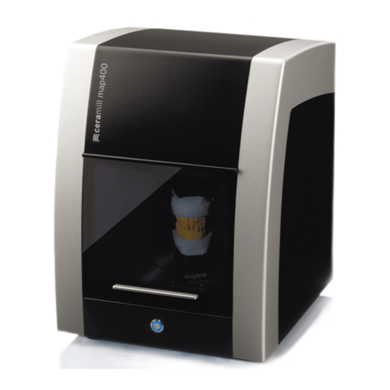
    D O N N É E S R E L A T I V E S À L ’ A P P A R E I L Composants et interfaces 4.4.2 Kit de transfert Ceramill 4.4.1 Ceramill Map400 Fig. 1 Vue d’ensemble de l’appareil face avant 1 Plaque de base Artex Scan 2 Touche de commande Fig.
  • Page 57: 4.4.3 Pc Type T3500

    La plaque de base Artex Scan est monté rigide- 4.4.3 PC Type T3500 ment dans le Scanner Ceramill Map400. C’est sur elle que doivent se fixer, suivant les besoins, les plaques d’écartement 1 7 et 2 6 et la plaque de fixation avec pince 5.
  • Page 58: Installation

    à l’intérieur dans des pièces sèches. ▷ Connectez la souris et le clavier au PC. _ La place min. nécessaire pour l’installation de Ceramill Map400 y compris les connexions est Installation du logiciel sur le PC de : ▷ Allumez le scanner par l’interrupteur principal.
  • Page 59: Installation Du Programme

    I N S T A L L A T I O N 5.4.1 Installation du programme antivirus Installation du scanner Pour la protection du PC : Comme chaque scanner est calibré indivi- ▷ Cliquez sur le bureau Microsoft Security Essen- duellement à...
  • Page 60: Calibration Des Axes

    I N S T A L L A T I O N Calibration des axes Synchronisation du fixateur Artex Le scanner Ceramill Map400 doit être calibré La synchronisation du fixateur doit être après l’installation et le branchement sur le PC à...
  • Page 61: Enregistrement Du Fixateur Artex

    I N S T A L L A T I O N ▷ Refermez le fixateur jusqu’à la butée et fixez-le AVERTISSEMENT : à l’aide de la vis latérale 6. ▷ Laissez polymériser suivant les instructions du Enregistrement erroné du fixateur ! ▷...
  • Page 62 I N S T A L L A T I O N ▷ Démarrez la base de données Ceramill Mind . ▷ Placez un cas patient fictif avec indications dans la mâchoire supérieure et inférieure (par ex. calotte dans la mâchoire supérieure et antagoniste dans la mâchoire inférieure). ▷...
  • Page 63 I N S T A L L A T I O N ▷ Choisissez le nombre de plaques d’écartement. ▷ Sous type de scan, cliquez sur Mâchoire complète Fig. 9 ▷ Démarrez le scan 3D à l’aide du bouton Continuer...
  • Page 64 I N S T A L L A T I O N ▷ Vérifiez le résultat du scan et, si nécessaire, refaites-le. Fig. 10 ▷ Suivez ensuite les instructions du logiciel. ▷ Retirez la mâchoire supérieure. ▷ Positionnez la mâchoire inférieure dans la plage de mesure à l’aide de la plaque d’écartement néces- saire (0, 1, 2 ou 1+2) dans le scanner (voir chapitre 6.2).
  • Page 65 ▷ Vissez ensuite la vis latérale du fixateur. ▷ Placez le fixateur dans le scanner. La pince de la plaque de fixation doit prendre dans l’embase du fixateur. Fig. 11 Fixateur dans Ceramill Map400 1 Fixateur Artex 5 Plaque de base Artex Scan...
  • Page 66 I N S T A L L A T I O N ▷ Démarrez le scan vestibulaire à l’aide du bouton Continuer ▷ Suivez ensuite les instructions du logiciel. ▷ Le logiciel demande l’alignement des 3 points pour l’enregistrement requis du fixateur. ▷...
  • Page 67 I N S T A L L A T I O N ▷ Placez trois points dans la mâchoire inférieure (sur les marquages du modèle). Entf/Del On peut effacer le dernier point à l’aide de la touche Fig. 12...
  • Page 68 I N S T A L L A T I O N ▷ Passez au scan vestibulaire à l’aide de la Barre d’espacement Fig. 13...
  • Page 69 I N S T A L L A T I O N ▷ Placez trois points sur les mêmes marquages en suivant le même ordre. La mâchoire inférieure est alignée. l'articulation En cas d’alignement erroné, il peut être recommencé à l’aide de la fonction Fig.
  • Page 70 I N S T A L L A T I O N ▷ Démarrez l’alignement de la mâchoire supérieure à l’aide du bouton Continuer Fig. 15...
  • Page 71 I N S T A L L A T I O N ▷ Effectuez l’enregistrement de la mâchoire supérieure de la même manière que pour la mâchoire infé- rieure. La mâchoire supérieure est alignée. Fig. 16...
  • Page 72 I N S T A L L A T I O N ▷ Démarrez l’alignement précis à l’aide du bouton Continuer Fig. 17...
  • Page 73 I N S T A L L A T I O N Après l’alignement précis des deux mâchoires : ▷ Démarrez le processus de correspondance à l’aide du bouton Continuer Les points définis pour l’enregistrement du fixateur sont enregistrés dans le logiciel. Fig.
  • Page 74: Instructions D'utilisation

    I N S T R U C T I O N S D ’ U T I L I S A T I O N Plus les points sont précis, plus l’alignement sera précis. De petites déviations sont permises et seront éliminées lors du processus de correspondance ! En cas d’alignement erroné...
  • Page 75: Informations Sur L'inscription Et Le Téléchargement

    INFORMATIONS SUR L’INSCRIPTION ET LE TÉLÉCHARGEMENT ▷ Vérifiez si les parties à scanner du modèle de Informations sur l’inscrip- tion et le téléchargement mâchoire sont bien dans la plage de mesure marquée. Inscription au Centre M Pour le téléchargement des mises à jour et pour pouvoir envoyer des données au centre de fabri- cation, vous devez vous inscrire sur la page du Centre M.
  • Page 76: Entretien

    D Y S F O N C T I O N N E M E N T S , R É P A R A T I O N S E T G A R A N T I E Protection de l’environne- Entretien ment...
  • Page 77: Caractéristiques Techniques

    Unité Type T3500 – N° d’article 179170 Sous réserve de modifications. Poids Type de proces- Intel Xenon Quad/ Caractéristiques techniques Ceramill Map400 seur / temps 2.67GHz Ceramill Mémoire de travail Unité Map400 – N° d’article 179140 Espace disque dis- Dimensions (p ×...
  • Page 78 Componenti ed interfacce ..81 4.4.1 Ceramill Map400 ....81 Anomalie, riparazioni e garanzia ..101 4.4.2 Ceramill Transfer Kit .
  • Page 79: I T

    S P I E G A Z I O N E D E I S I M B O L I Spiegazione dei simboli Ulteriori simboli nelle istruzioni d'uso Indicazioni di avvertimento Simbolo Significato ▷ Punto della descrizione di una ope- Nel testo le indicazioni di avvertimento razione sono contrassegnate da un triangolo di...
  • Page 80: Indicazioni Generali Di Sicurezza

    (incl. articolatore vir- osservate le seguenti indicazioni di sicurezza: tuale) AVVERTENZA: _ Scanner Ceramill Map400 (179140) ▪ Transfer Kit Funzionamenti difettosi in apparecchio difet- ▪ Sagoma campo di misura toso! ▪ Cavo USB (2 ×) In caso di individuazione di un danno oppure di ▪...
  • Page 81: Uso Conforme A Destinazione

    D A T I R E L A T I V I A L L ' A P P A R E C C H I O Uso conforme a destinazione Componenti ed interfacce Il Ceramill Map400 è uno scanner in 3D coman- 4.4.1 Ceramill Map400 dato da PC per il rilevamento di modelli dentali.
  • Page 82: 4.4.2 Ceramill Transfer Kit

    4.4.2 Ceramill Transfer Kit Il supporto di scansione Artex è fissato allo Scan- ner Ceramill Map400. A seconda della necessità sul supporto vengono avvitate le piastre distan- ziatrici 1 7 e 2 6 e la piastra di fissaggio con dispo- sitivo di bloccaggio 5.
  • Page 83: Installazione

    _ L'apparecchio è destinato esclusivamente per ▷ Collegare mouse e tastiera al PC. l'utilizzo in locali chiusi ed asciutti. _ L'ingombro minimo per Ceramill Map400, colle- Installazione del software sul PC gamenti inclusi, è di: ▷ Accendere lo scanner con l'interruttore princi- ▪...
  • Page 84: Installazione Dei Software

    I N S T A L L A Z I O N E 5.4.1 Installazione del programma antivirus Installazione dello scanner Per la protezione del PC: Poiché ogni scanner ha una calibrazione ▷ Cliccare sul desktop Microsoft Security Essen- individuale di fabbrica, i dati sul CD di tials installazione sono validi esclusivamente Questo link rimanda alla homepage della Micro-...
  • Page 85: Calibrazione Degli Assi

    Calibrazione degli assi Sincronizzazione del fissatore Artex Dopo l'installazione ed il collegamento al PC, lo scanner Ceramill Map400 deve essere calibrato La sincronizzazione del fissatore con la con l'ausilio del modello di calibrazione fornito in chiave Splitex dovrebbe essere controllata dotazione.
  • Page 86: Registrazione Del Fissatore Artex

    I N S T A L L A Z I O N E ▷ Abbassare il fissatore fino alla battuta e fissarlo INDICAZIONE: con la vite laterale 6. ▷ Lasciare indurire il collegamento a colla come Registrazione errata del fissatore! ▷...
  • Page 87 I N S T A L L A Z I O N E ▷ Avviare il database Ceramill Mind. ▷ Aprire un caso di un paziente fittizio con indicazioni nell'arcata superiore & inferiore (ad es. cappetta nell'arcata superiore e antagonista nell'arcata inferiore) ▷...
  • Page 88 I N S T A L L A Z I O N E ▷ Selezionare il numero delle piastre distanziatrici. ▷ Selezionare nel campo tipo di scansione Arcata Completa Fig. 9 ▷ Avviare la scansione in 3D tramite il pulsante Avanti...
  • Page 89 I N S T A L L A Z I O N E ▷ Controllare il risultato della scansione e, se necessario, effettuare nuovamente la scansione. Fig. 10 ▷ Seguire le istruzioni del software. ▷ Rimuovere l'arcata superiore. ▷ Posizionare nello scanner l'arcata inferiore nel campo di misura, utilizzando la piastra distanziatrice necessaria (0, 1, 2 o 1+2) (vedi capitolo 6.2).
  • Page 90 ▷ Successivamente serrare la vite laterale del fissatore. ▷ Inserire il fissatore nello scanner. Il dispositivo di fissaggio della piastra di fissaggio deve fare presa nella branca inferiore del fis- satore. Fig. 11 Fissatore nel Ceramill Map400 1 Fissatore Artex 4 Piastra distanziatrice (opzionale) 2 Vite...
  • Page 91 I N S T A L L A Z I O N E ▷ Avviare con il pulsante Avanti la scansione vestibolare. ▷ Seguire le istruzioni del software. ▷ Il software richiede per la registrazione necessaria del fissatore la correlazione a 3 punti. ▷...
  • Page 92 I N S T A L L A Z I O N E ▷ Applicare tre punti nell'arcata inferiore (sulle marcature del modello). Entf/Del Con il tasto è possibile cancellare di nuovo il punto applicato per ultimo. Fig. 12...
  • Page 93 I N S T A L L A Z I O N E ▷ Con la barra spaziatrice commutare sulla scansione vestibolare. Fig. 13...
  • Page 94 I N S T A L L A Z I O N E ▷ Applicare qui nella stessa sequenza tre punti sulle stesse marcature. L'arcata inferiore viene correlata. Qualora la correlazione fosse stata effettuata in modo errato, è possibile ripeterla tramite la articolazione funzione Fig.
  • Page 95 I N S T A L L A Z I O N E ▷ Avviare con il pulsante Avanti la correlazione dell'arcata superiore. Fig. 15...
  • Page 96 I N S T A L L A Z I O N E ▷ Effettuare la registrazione dell'arcata superiore nello stesso modo dell'arcata inferiore. L'arcata superiore viene correlata. Fig. 16...
  • Page 97 I N S T A L L A Z I O N E ▷ Avviare con il pulsante Avanti l'allineamento di precisione. Fig. 17...
  • Page 98 I N S T A L L A Z I O N E Dopo l'allineamento di precisione di entrambe le arcate: ▷ Avviare con il pulsante Avanti il processo di matching. I punti definiti per la registrazione del fissatore vengono registrati nel software. Fig.
  • Page 99: Indicazioni Per L'impiego

    I N D I C A Z I O N I P E R L ' I M P I E G O Tanto più precisamente saranno applicati i punti, tanto più precisa sarà la correlazione. Piccole differenze sono permesse e vengono eliminate nel processo di matching! Qualora la correlazione venisse effettuata in modo errato: ▷...
  • Page 100: Registrazione Ed Informazioni Per Il

    R E G I S T R A Z I O N E E D I N F O R M A Z I O N I P E R I L D O W N L O A D ▷...
  • Page 101: Manutenzione

    A N O M A L I E , R I P A R A Z I O N I E G A R A N Z I A Protezione dell'ambiente Manutenzione La manutenzione deve essere effettuata esclusi- Imballo vamente da personale specializzato espressa- Per quanto riguarda l'imballo AmannGirrbach mente istruito.
  • Page 102: Dati Tecnici

    D A T I T E C N I C I Dati tecnici Dati tecnici PC Unità Tipo T3500 Con riserva di modifiche. – No. Art. 179170 Peso Dati tecnici Ceramill Map400 Tipo e ciclo del Intel Xenon Quad/ Ceramill processore 2.67GHz Unità Map400 Memoria di lavoro –...
  • Page 103 Fallos, reparaciones y garantía ..127 4.4.1 Ceramill Map400 ....107 Fallos ......127 4.4.2 Kit de transferencia Ceramill .
  • Page 104: Simbología Empleada

    S I M B O L O G Í A E M P L E A D A Simbología empleada Símbolos adicionales en el manual Advertencias de peligro Símbolo Significado ▷ Punto en el que se describe una Las advertencias de peligro se identifican acción con un triángulo de señalización sobre fondo de color con el texto encuadrado.
  • Page 105: Instrucciones De Seguridad Generales

    I N S T R U C C I O N E S D E S E G U R I D A D G E N E R A L E S Instrucciones de seguri- Aptitud del personal dad generales OBSERVACIÓN: Al instalar, poner en marcha, o utilizar el aparato, El aparato solamente lo deberá...
  • Page 106: Datos Sobre El Aparato

    D A T O S S O B R E E L A P A R A T O Datos sobre el aparato Volumen de entrega del sistema Utilización reglamentaria completo (incl. articulador virtual) El Ceramill Map400 es un escáner 3D controlado _ Escáner Ceramill Map400 (179140) por PC para registrar modelos dentales. ▪ Kit de transferencia OBSERVACIÓN: ▪...
  • Page 107: Componentes, Puertos E

    D A T O S S O B R E E L A P A R A T O Componentes, puertos e interfases 4.4.2 Kit de transferencia Ceramill 4.4.1 Ceramill Map400 Fig. 1 Componentes frontales del aparato 1 Artex Scan Base Plate 2 Botón de manejo Fig.
  • Page 108: 4.4.3 Pc Tipo T3500

    La placa Artex Scan Base Plate va fijada de forma 4.4.3 PC tipo T3500 inamovible al Scanner Ceramill Map400. A ella se atornillan las placas de suplemento 1 7 y 2 6 que se precisen y la placa de fijación con garra 5. Las placas de suplemento y el tornillo 3 necesarios dependen de la altura del modelo a sujetar.
  • Page 109: Instalación

    I N S T A L A C I Ó N Instalación Transporte Instalación del PC ▷ Alzar entre dos personas el aparato por la placa ▷ Conectar el cable de red al conector de alimen- base y transportar lo. tación del PC y enchufarlo a la red.
  • Page 110: Instalación Del Programa Antivirus

    I N S T A L A C I Ó N 5.4.1 Instalación del programa antivirus Instalación del escáner Para proteger el PC: Ya que todo escáner viene calibrado indi- ▷ En el Escritorio haga clic sobre Microsoft Secu- vidualmente de fábrica, los datos del CD de rity Essentials instalación son solamente válidos para el Este enlace le remite a la página web de Micro-...
  • Page 111: Calibración De Los Ejes

    Unificación del Artex Fixator Una vez colocado y conectado al PC, el escáner La unificación del Fixator con la llave Spli- Ceramill Map400 deberá ser calibrado con el tex deberá comprobarse periódicamente. modelo de calibración adjunto. ▷ Montar la placa de suplemento nº 1, la placa de Antes de utilizar en el escáner el Artex Fixator es...
  • Page 112: Registro Del Artex Fixator

    I N S T A L A C I Ó N ▷ Dejar endurecer el adhesivo según indicaciones OBSERVACIÓN: de aplicación del mismo. ▷ Abrir el Fixator. ¡Registro incorrecto del Fixator! ▷ Siempre montar los modelos maxilares sobre ▷ Retirar la llave Splitex. zócalo de yeso en el escáner.
  • Page 113 I N S T A L A C I Ó N ▷ Arrancar Ceramill Mind Database. ▷ Abrir un expediente de paciente ficticio, con indicaciones en los maxilares superior e inferior (p. ej. funda en el maxilar superior y un antagonista en el inferior) ▷...
  • Page 114 I N S T A L A C I Ó N ▷ Determinar la cantidad necesaria de placas de suplemento. ▷ Elegir bajo el punto Tipo de escaneo Arcada Completa Fig. 9 ▷ Arrancar el escaneo 3D con el botón Continuar...
  • Page 115 I N S T A L A C I Ó N ▷ Verificar el resultado, y repetir si fuese insatisfactorio. Fig. 10 ▷ Seguir las instrucciones indicadas en el software. ▷ Retirar el maxilar superior. ▷ Ubicar el maxilar inferior en el escáner, empleando la placa de suplemento necesaria (0, 1, 2 ó 1+2) para que éste quede dentro del campo de medición (ver capítulo 6.2).
  • Page 116 ▷ A continuación, apretar el tornillo lateral del Fixator. ▷ Colocar el Fixator en el escáner. La garra de la placa de fijación deberá encajar en la parte inferior del Fixator Fig. 11 Fixator en el Ceramill Map400 1 Artex Fixator 5 Artex Scan Base Plate 2 Tornillo 3 Placa de fijación con garra...
  • Page 117 I N S T A L A C I Ó N ▷ Arrancar el escaneo vestibular con el botón Continuar ▷ Seguir las instrucciones indicadas en el software. ▷ El software precisa la correspondencia determinada con el método de 3 puntos para poder registrar el Fixator.
  • Page 118 I N S T A L A C I Ó N ▷ Fijar tres puntos en el maxilar inferior (en las marcas del modelo). Entf/Del Con la tecla puede borrarse el último punto fijado. Fig. 12...
  • Page 119 I N S T A L A C I Ó N ▷ Accionar la barra espaciadora para acceder al escaneo vestibular. Fig. 13...
  • Page 120 I N S T A L A C I Ó N ▷ Fijar allí también tres puntos en las mismas marcas y siguiendo el mismo orden. Se determina la correspondencia con el maxilar inferior. articulación Si la correspondencia no es correcta es posible repetirla empleando la función Fig.
  • Page 121 I N S T A L A C I Ó N ▷ Arrancar la correspondencia del maxilar superior con el botón Continuar Fig. 15...
  • Page 122 I N S T A L A C I Ó N ▷ Realizar el registro del maxilar superior de igual manera que en el inferior. Se determina la correspondencia con el maxilar superior. Fig. 16...
  • Page 123 I N S T A L A C I Ó N ▷ Arrancar el posicionamiento fino con el botón Continuar Fig. 17...
  • Page 124 I N S T A L A C I Ó N Una vez concluido el posicionamiento fino de ambos maxilares: ▷ Iniciar el proceso de emparejamiento con el botón Continuar El software guarda los puntos definidos para el registro del Fixator. Fig.
  • Page 125: Instrucciones De Aplicación

    I N S T R U C C I O N E S D E A P L I C A C I Ó N Cuanto más exactos se determinen los puntos tanto más exacta es su correspondencia. Sin embargo, se permiten ligeras variaciones, ya que éstas son corregidas durante el proceso de emparejamiento.
  • Page 126: Registro E Información Sobre

    R E G I S T R O E I N F O R M A C I Ó N S O B R E D E S C A R G A S ▷ Controlar si las zonas a escanear en el modelo Registro e información sobre descargas del maxilar se encuentran dentro del campo de...
  • Page 127: Limpieza Y Mantenimiento

    L I M P I E Z A Y M A N T E N I M I E N T O Limpieza y mantenimiento Reparaciones Las reparaciones solamente deberán llevarse a Limpieza cabo por personal especializado. El escáner deberá limpiarse con regularidad. ▷...
  • Page 128: Datos Técnicos

    D A T O S T É C N I C O S Datos técnicos Datos técnicos del PC Unidad Tipo T3500 Salvo modificación. – Nº de art. 179170 Peso Datos técnicos Ceramill Map400 Procesador/reloj Intel Xenon Quad/ Uni- Ceramill 2.67GHz Map400 Memoria RAM GB RAM –...
  • Page 132 Made in the European Union ISO 9001 Manufacturer | Hersteller Distribution | Vertrieb Distribution | Vertrieb D/A Amann Girrbach AG Amann Girrbach GmbH Herrschaftswiesen 1 Dürrenweg 40 austria@amanngirrbach.com 6842 Koblach | Austria 75177 Pforzheim | Germany germany@amanngirrbach.com Fon +43 5523 62333-105...

Table des Matières