Publicité
Les langues disponibles
Les langues disponibles
Liens rapides
Manuale d'installazione, uso e manutenzione
Installation, use and maintenance manual
Manuel d'installation, d'utilisation et d'entretien
Installations-, Bedienungs- und Wartungsanleitung
Manual de instalación, uso y mantenimiento
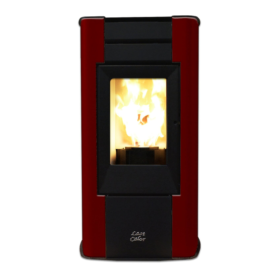
Stufa a pellet mod - Pellet stove model - Poêle à granulés mod.
Pelletofen Modell - Estufa de pellets mod.
Leggere attentamente le istruzioni prima dell'installazione, utilizzo e manutenzione.
Read the instructions carefully before installation, use and maintenance.
Lire attentivement les instructions avant d'installer, d'utiliser et d'entretenir le poêle.
Vor Installation, Gebrauch und Wartung muss diese Anleitung aufmerksam durchgelesen werden.
Das Handbuch ist wesentlicher Bestandteil des Geräts.
Lea atentamente las instrucciones antes de realizar la instalación, el uso y el mantenimiento.
TERMO-VIOLA
Il manuale è parte integrante dell'apparecchio.
The manual is an integral part of the unit.
Le manuel fait partie intégrante de l'appareil.
El manual es parte integrante del equipo.
1
48421Y140-M5_06/14
Hardware - M
TERMO-VIOLA
Publicité

Manuels Connexes pour Last Calor TERMO-VIOLA


Sommaire des Matières pour Last Calor TERMO-VIOLA
- Page 1 Manual de instalación, uso y mantenimiento Stufa a pellet mod - Pellet stove model - Poêle à granulés mod. Pelletofen Modell - Estufa de pellets mod. TERMO-VIOLA 48421Y140-M5_06/14 Hardware - M Leggere attentamente le istruzioni prima dell’installazione, utilizzo e manutenzione.
- Page 2 TERMO-VIOLA...
- Page 3 TERMO-VIOLA...
- Page 4 La garantia del prododucto decae por qualquier incovenitente de rotura o incidente debido a la falta de respeto o aplicaciòn de las indicaciones indicadas en el presente manual . TERMO-VIOLA...
- Page 5 TERMO-VIOLA...
- Page 6 TERMO-VIOLA...
- Page 7 TERMO-VIOLA...
- Page 8 TERMO-VIOLA...
- Page 66 4.4.2Modification du préréglage de la température de l'eau 4.4.3 Remise en marche à partir du mode VEILLE (STAND-BY) 4.4.4 Nettoyage du brasier 4.4.5 Eau chaude sanitaire avec échangeur rapide. 4.4.6 Eau chaude sanitaire avec un préparateur d’eau chaude. 4.4.7Installation avec un ballon d’accumulation 4.5 Extinction TERMO-VIOLA...
- Page 67 N'utiliser que des pièces de rechange d'origine. La société Cola s.r.l. décline toute responsabilité pour les inconvénients, les ruptures ou les accidents causés par l'inobservation ou l'inapplication des indications contenues dans ce manuel. TERMO-VIOLA...
- Page 68 G - Raccordement tuyau d'évacuation des fumées, Ø 80 mm H - Tableau de commande mod. F047 I - Couvercle de réservoir à granulés L - Pieds (Vérins) réglables M - Bouton de secouage des turbulateurs N - Raccordement tuyau d'évacuation des fumées postériur, Ø 80 mm (Opt.) TERMO-VIOLA...
- Page 69 Accessoires fournis La fourniture comprend : câble d'alimentation électrique ; manuel d’installation, utilisation et entretien ; clé d'ouverture - de fermeture ; TERMO-VIOLA...
- Page 70 Il est recommandé de poser délicatement le poêle au sol pour éviter tout choc éventuel, et de l'installer dans la zone prévue ; s'assurer également que le plancher est assez solide pour supporter le poids du poêle ; dans le cas contraire, consulter un technicien spécialisé. TERMO-VIOLA...
- Page 71 En cas d'installation du poêle sur un parquet (moquette ou linoléum), prévoir une plaque de sol conformément aux prescriptions du DTU en vigueur. Il est toujours conseillé d'installer des équipements anti-incendie appropriés. TERMO-VIOLA...
- Page 72 (les fumées) ; - elle doit pouvoir assurer une dilution adéquate des produits et être positionnée en dehors de la zone de reflux ; - elle ne doit pas comporter de moyens mécaniques d'aspiration. TERMO-VIOLA...
- Page 73 TERRE Sonde ambiante VANNE 3 VOIES additionnel Sonde de température „fumées“ ALT= Thermostat de sécurité chambre de combustion BOUGIE ALD= Dépressiomètre ALP= Thermostat de sécurité réservoir à granulés VENTILATEUR POMPE VIS SANS FIN D’EXTRACTION DES FUMÉES Encodeur vérificateur fumées TERMO-VIOLA...
- Page 74 ; il est donc conseillé de contrôler le serrage des colliers des circulateurs et de la chambre de combustion pendant le remplissage d'eau et après les premières heures de service, ainsi que de purger l'air résiduel dans le circuit. TERMO-VIOLA...
- Page 75 Il est toujours conseillé d'installer des équipements anti-incendie appropriés. En cas d'incendie : - Débrancher immédiatement le câble d'alimentation du poêle. - Éteindre le feu avec des extincteurs (à poudre). - Appeler immédiatement les sapeurs-pompiers. - Ne pas utiliser de jets d'eau pour éteindre le feu. TERMO-VIOLA...
- Page 76 élevées (< 85 °C), car la quantité de granulés dans le brasier est réduite. Cette anomalie peut entraîner une légère fuite de fumées dans la pièce, mais ne comporte aucun risque. Il est interdit d’intervenir sur les dispositifs de sécurité. TERMO-VIOLA...
- Page 77 ‘P4’, une touche de fonction SET/MENU ‘P3’, quatre touches de menu ‘P1’, ‘P2’, ‘P5’, ‘P6’ et 7 LED de signalisation de l'état de fonctionnement du poêle. Indicateurs d'état Indications écran supérieur Indications écran supérieur Écran LCD rétro-éclairé Récepteur IR Indications écran inférieur TERMO-VIOLA...
- Page 78 Résistance électrique la partie gauche de l'écran. L'activation, à l'écran, d'un des segments signale la mise en service du dispositif correspondant, suivant la liste ci-contre. Vis sans fin Extracteur de fumées Activation du circuit SANITAIRE Activation du circuit CHAUFFAGE ALARME TERMO-VIOLA...
- Page 79 Température ambiante < CONSIGNE température FONCTIONNEMENT Température de l’eau < CONSIGNE eau MODULE Température des fumées FONCTIONNEMENT Avec une fréquence Pr03 NETTOYAGE DU BRASIER MODULE FONCTIONNEMENT ON/OFF pour éteindre NETTOYAGE FINAL (*) Pr39 S’écoule à partir du moment où T. fumées. < Pr13 TERMO-VIOLA...
- Page 80 Pour modifier la température ambiante, il suffit de sélectionner l'option AFFICHE T°AMBIANTE en appuyant sur le bouton P2 . Appuyer ensuite sur les boutons ‘P1’ et ‘P2’ : sur l'écran apparaîtra l'état courant de la CONSIGNE (SET) de température. Valeur préréglée de la température ambiante Bouton ‘P1’ Bouton ‘P2’ Fenêtre de dialogue TERMO-VIOLA...
- Page 81 Après l'extinction, le poêle se met en condition refroidissement en amenant la vitesse d'extraction des fumées à la valeur préréglée pour le nettoyage du creuset. Le redémarrage survient dès que la température ambiante a atteint la valeur de CONSIGNE (SET). TERMO-VIOLA...
- Page 82 Quand la température de consigne du ballon est atteinte, le poêle se met en mode “ATTENTE DEMANDE” (si le paramètre STAND-BY est réglé sur ON, voir paragraphe. 4.6.5). Si le poêle est en “ARRET”, il ne s’allume pas et ne fait pas de production de chaleur. TERMO-VIOLA...
- Page 83 02 – program jour 01 – chrono jour on / off 02 – start 1 jour heure 03 – stop 1 jour heure 04 – start 2 jour heure 05 – stop 2 jour heure 03 – program semaine TERMO-VIOLA...
- Page 84 04 – choix de la langue 01 - italien 02 - français 03 - anglais 04 - allemand 05 – mode veille (stand-by) on / off 06 – alarme sonore (buzzer) on / off 07 – chargement initial 08- État du poêle TERMO-VIOLA...
- Page 85 OFF dans le champ horaires, l'horloge ignorera la commande correspondante. La programmation doit se faire avec grande attention. Fenêtre de dialogue Éviter de faire chevaucher les heures d'activation et/ou de désactivation dans le même jour au sein de différents programmes. TERMO-VIOLA...
- Page 86 Pour éviter des mises en marche et des extinctions du poêle non désirées, activer un seul programme à la fois. Désactiver le programme journalier si l'on souhaite utiliser le programme hebdomadaire ; il est convient dans ce cas de désactiver le programme week-end. TERMO-VIOLA...
- Page 87 L : LED allumée après l'appui d'une touche quelconque Touche P1+P6 : Allumage-extinction du poêle Touche P1 : Augmentation de la température ambiante Touche P6 : Augmentation du niveau de puissance Touche P5 : Diminution du niveau de puissance Touche P2 : Diminution de la température ambiante TERMO-VIOLA...
- Page 88 électronique les deux fils du thermostat de leurs bornes respectives TERM ; remonter le tout et vérifier le fonctionnement correct de l'appareil. Voici la procédure de présélection à suivre : - thermostat externe : présélectionner une CONSIGNE (SET) température de 7 °C ; TERMO-VIOLA...
- Page 89 à l'air de combustion de passer à travers les orifices du creuset de sorte à garantir une combustion efficace. brasier doit parfaitement plaquer sur tout le périmètre de son support sans laisser aucun interstice pour le passage d'air. Brasier encrassé Brasier propre Support de brasier propre TERMO-VIOLA...
- Page 90 Cette opération doit être effectuée poêle éteint et froid. Boutons de commande droit - gauche du secouage des turbulateurs en position basse de fonctionnement du poêle chaudière. TERMO-VIOLA...
- Page 91 1 - Soupape de sûreté 2 - Couvercle de chambre de combustion 3 - Protection en isolcart 4 - Bouton de secouage des turbulateurs 5 - Protection en vermiculite 6 - Cadre inférieur du couvercle 7 - Turbulateurs 8 - Chambre de combustion TERMO-VIOLA...
- Page 92 Légende : 1 - Joint de réservoir-convoyeur 2 - Flasque d'arrêt motoréducteur 3 - Motoréducteur 4 - Vis sans fin 5 - Joint pour goulotte 6 - Goulotte de granulés 7 - Joint de chambre-convoyeur 8 - Convoyeur de granulés TERMO-VIOLA...
- Page 93 3 - Soupape de sûreté 4 - Raccordement remplissage de l'installation 5 - Circulateur circuit chauffage 6 - Retour pompe - chambre de combustion 7 - Transducteur de pression 8 - Raccordement vase d'expansion 9 - Purgeur 10 - Conduit de départ TERMO-VIOLA...
- Page 94 THERMIQUE surchauffe en agissant sur le chambre de combustion. combustion et a donc bloqué le bouton de réarmement. -Le système est arrêté. fonctionnement du motoréducteur. TERMO-VIOLA...
- Page 95 La société COLA s.r.l. se réserve d'apporter des modifications techniques ou esthétiques à ses produits à n'importe quel moment et sans préavis. Toutes les configurations, les dessins, les mesures et les schémas sont fournis à titre d'exemple. TERMO-VIOLA...