Gorgy Timing LEDI Mode D'emploi
Masquer les pouces
Voir aussi pour LEDI:
- Mode d'emploi (194 pages) ,
- Mode d'emploi (94 pages) ,
- Mode d'emploi (28 pages)

Manuels Connexes pour Gorgy Timing LEDI


Sommaire des Matières pour Gorgy Timing LEDI
- Page 1 LEDI NETWORK ITS ® LEDI NETWORK SERvER ® MODE D’EMPLOI - page 3 USER GUIDE - page 65 MDE-LEDInetworkITS-server-4078V1.3...
- Page 2 éviter toute perturbation. (garder quelques centimètres de distance) Gorgy Timing décline toute responsabilité en cas d’accidents ou de dommages provoqués par une mauvaise utilisation du produit. Les produits GORGY TIMING sont conformes aux normes : CE, EN 60950, EN 55022, EN 50024. MDE-LEDInetworkITS-server-4078V1.3...
-
Page 3: Table Des Matières
1.3.3. Le logiciel NTP......................12 A/ Les états du logiciel du client NTP................12 B/ Les états du serveur NTP ..................13 1.3.4. La Base de Temps de la Ledi Network ITS/DCLS/NTP Server ......14 INSTaLLaTION COMPLETE ..................15 2.1. Configuration réseau ......................15 2.1.1. - Page 4 4. Modification du format du signal d’entrée des cartes Top IRIG-B DCLS ....... 53 4.1. Switchs de la carte principale de la LEDI Network DCLS ......... 53 4.2. Switchs de la carte principale de la LEDI Network ITS ..........55 aNNExE E –...
-
Page 5: Introduction
INTRODUCTION Ce document est le manuel d’utilisation pour les produits « LEDI NETWORK ITS », « LEDI ® NETWORK DCLS » et « LEDI Network NTP Server ». Ces appareils se synchronisent ® ® soit par GPS, par code AFNOR NFS87500 ou par signal radio TDF ou DCF. Ils dispo- sent de sorties de synchronisation optionnelles (ASCII+TOP, AFNOR NFS87500, IRIG-B, alarme, second serveur NTP). -
Page 6: Installation Rapide
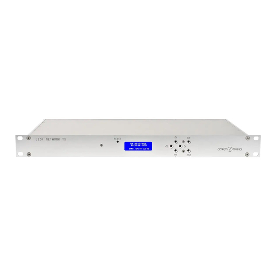
Le produit lui-même : un rack 1U 19”. ► Le nom de ce produit est LEDI NETWORK ITS ou DCLS ou NTP SERvER qui est écrit sur la face avant du rack. ► Le code et la configuration du produit peuvent être vérifiés sur l’étiquette d’iden- tification située dessous ou derrière le produit. -
Page 7: Connecter Le Produit
Connecter les sorties de synchronisation à votre équipement (voir annexe a – Connections pour plus d’informations). Connecter la LEDI Network ITS/DCLS/NTP Server à votre réseau en utilisant le câble réseau. Connecter la LEDI Network ITS/DCLS/NTP Server à une alimentation en utili- sant le câble d’alimentation lorsqu’il est présent. -
Page 8: Configuration Des Cartes De Sorties
Selon votre logiciel client NTP, vous pouvez vous attendre à une précision de l’ordre de quelques millisecondes. 1/ Avec la GT LEDI Network ITS (client NTP), la précision est inférieure à une milliseconde. MDE-LEDInetworkITS-server-4078V1.3... -
Page 9: Concept De Synchronisation
Principes de correction horaire L’objectif de la synchronisation est d’avoir deux horloges indiquant la même heure. Dans le cas de la synchronisation par NTP, l’horloge de la LEDI Network ITS/NTP Ser- ver doit indiquer la même heure que le serveur de temps NTP. - Page 10 ► Dérive : C’est la différence de fréquence entre les deux horloges. Quand il y a dérive, sans correction, l’offset entre les deux horloges augmente et diminue selon le signe de la dérive. La figure suivante montre comment se déroule l’évolution des deux horloges avec et sans dérive : Heure serveur Dérive nulle Heure serveur...
-
Page 11: B/ Dialogue Réseau
INTRODUCTION B/ Dialogue réseau La dérive et l’offset réel de l’horloge de la LEDI Network ITS/NTP Server reliée au ser- veur NTP sont estimés à partir de l’offset mesuré. Cet offset est calculé en soustrayant la date de l’horloge du client à la date de l’horloge du serveur. -
Page 12: Le Logiciel Ntp
► auto-détection : L’auto-détection de serveur est activée. Le client NTP essaye de trouver les ser- veurs Gorgy Timing. Au moins un serveur détecté est exigé pour quitter cet état. ► Apprentissage : Le logiciel de client NTP a trouvé un ou plusieurs produits Gorgy-Timing (auto-détection activée) ou fonctionne avec les serveurs configurés. -
Page 13: B/ Les États Du Serveur Ntp
INTRODUCTION B/ Les états du serveur NTP La figure suivante montre les différents états du serveur NTP : Run autonomously Idle Startup Locked Failure Rescaling Rescaled/Tracking Autonomous Voici la signification de ces états : Idle ► Etat indéterminé, juste après le démarrage. ►... -
Page 14: La Base De Temps De La Ledi Network Its/Dcls/Ntp Server
La stabilité dans ce mode dépend du quartz présent. 1.3.4. La Base de Temps de la Ledi Network ITS/DCLS/NTP Server Le noyau de la base de temps est un OCXO de haute précision (voir l’annexe E - données). -
Page 15: Installation Complete
Cette requête contient un nom DHCP. Il y a deux cas : ► Si un serveur DHCP est installé sur votre réseau, il enregistre la demande DHCP et renvoie une adresse IP. La LEDI Network ITS/DCLS/NTP Server démarre avec cette nouvelle adresse. ►... -
Page 16: Changer Les Paramètres Réseaux
2.1.2. Changer les paramètres réseaux Utiliser l’outil GTNetManager fournit sur le CD-ROM pour configurer votre produit : Insérer le CDROM dans le lecteur de votre PC puis lancer le programme GTNet- Manager localisé dans le répertoire Common\Configuration L’utilitaire GTNetManager affiche automatiquement les produits GORGY TIMING installés sur le réseau comme ci-dessous : Nom, numéro de série Masque de sous-... -
Page 17: Installation Complete
INSTaLLaTION COMPLETE Double-cliquer sur la ligne correspondant au produit que vous souhaitez confi- gurer. La fenêtre suivante apparaît : Nom du produit Numéro de série (040204) Localisation (Test Line) Adresse Ethernet (MAC) du produit Localisation du produit Entrer les paramètres réseau et la localisation, puis cliquer sur Set! Le produit redémarre avec ses nouveaux paramètres. -
Page 18: Intégration À Votre Réseau
DHCP. Puis, vous pouvez accéder au produit à partir de votre navigateur WEB ou du navigateur SNMP. Par exemple si vous donnez le nom DHCP ntpsrv1 à votre LEDI ITS/DCLS/NTP Server, vous pouvez simplement taper ntpsrv1 dans la zone d’adresse de votre navigateur WEB. -
Page 19: Configuration Des Cartes De Sorties
2.2. CONfIGURaTION DES CaRTES DE SORTIES 2.2.1. Introduction votre LEDI Network ITS peut être équipée jusqu’à 3 cartes (4 pour la LEDI Network DCLS). Chaque carte de sortie est synchronisée sur le code horaire NTP reçu du ser- veur NTP ou du GPS ou de la carte d’entrée IRIG B. Chaque carte agit en tant que traducteur qui recevant l’heure de la source principale de synchronisation et de la sortie... -
Page 20: Changer Les Paramètres
2.2.3. Changer les paramètres Ouvrir la page WEB de la LEDI Network ITS/DCLS/NTP Server (voir la partie 5). Cliquer sur le bouton Output. La configuration actuelle de votre produit apparaît à l’écran. Dans cet écran vous pouvez paramétrer chaque carte indépendamment (voir page 31). -
Page 21: Afficheur Face Avant
Au démarrage, l’heure et la date sur la LEDI Network ITS/DCLS/NTP Server ne sont pas valides et ne sont donc pas affichées. ► Au démarrage, l’heure et la date sur la LEDI Network 1/S/RK Enhanced ne sont pas valides et ne sont donc pas affichées. ►... -
Page 22: Affichage Horaire
3.2. affIChaGE hORaIRE Lorsqu’aucune alarme n’est présente et que le code horaire est présent sur l’entrée de la LEDI Network ITS/DCLS/NTP Server, l’heure courante du serveur est affichée en perma- nence. ► Lorsque l’afficheur est configuré pour donner l’heure UTC, les informations sui- vantes sont affichées par alternance :... -
Page 23: Alarme Mineure
L’écart de temps en entrée a dépassé le seuil de sécurité (security threshold configuré dans la page WEB). La LEDI Network se bloque et ne délivre plus l’heure sur ses sorties ni sur le réseau. L’afficheur indique « LOCKED ». Il faut accéder à... -
Page 24: Interface Web
WEB (comme ci-dessous), et appuyer sur Entrée. 4/ Si vous avez configuré votre LEDI NETWORK ENHANCED en mode DHCP et que votre serveur enregistre automatiquement l’identificateur DHCP dans le DNS, vous pouvez entrer le nom DHCP au lieu de l’adresse IP... -
Page 25: Description De L'interface Web
INTERfaCE WEB 4.2. DESCRIPTION DE L’INTERfaCE WEB 4.2.1. Ecran principal Voici l’écran qui doit apparaître lorsque vous accédez au site WEB de la LEDI Network ITS/DCLS/NTP. Les trois premiers boutons à gauche de l’écran permettent d’accéder aux panneaux suivants : ►... -
Page 26: Réglages Standards
Pendant le redémarrage, les sorties sont désactivées. voici les différents paramètres: ► IP mode Indique si la LEDI Network ITS/DCLS/NTP fonctionne en adresse IP fixe (entrée dans le champ IP address) ou avec le protocole DHCP (l’identificateur DHCP est entré dans le champ DHCP identifier). ►... -
Page 27: Informations Sur Le Produit
INTERfaCE WEB INfORMaTIONS SUR LE PRODUIT voici une description de la zone d’informations sur le produit: hardware GT serial number ► Affiche le numéro de série Gorgy-Timing du produit. C’est un numéro à 6 chiffres qui doit être identique à celui collé sous ou derrière le produit. ►... -
Page 28: Etat Du Produit
Choix possible entre LI&STRATUM unchanged, STRaTUM=0,LI un- changed, STRATUM unchanged,LI=3(11b), STRATUM=0, LI=3(11b) La LEDI Network ITS peut être synchronisée avec au plus trois serveurs NTP. En fait, le logiciel NTP utilise seulement un seul serveur à la fois mais peut permuter sur un autre serveur quand il n’y a plus ou pas suffisamment de réponses. -
Page 29: Description Du Client
La partie du milieu l’écran NTP vous permet de configurer le mode de synchronisation et les serveurs NTP utilisés : Si vous choisissez l’auto-détection dans le menu déroulant, la LEDI Network ITS / DCLS / NTP essaie d’utiliser les serveurs présents sur votre réseau. Si vous ne choi- sissez pas l’auto-détection, vous devez indiquer le mode de synchronisation et les... - Page 30 La table suivante peut vous aider à choisir les paramètres les plus appropriés : Mode Nombre de serveur Description NTP utilisé Utilise seulement un serveur pour la synchroni- One server sation Utilise le premier serveur au démarrage. Si ce serveur ne fonctionne plus correctement, le Two servers produit bascule sur le second serveur.
-
Page 31: Configuration De L'entrée De Synchronisation
Base de temps ► Run autonomously Cochez cette case si vous souhaitez que votre LEDI Network ITS/DCLS/NTP fonc- tionne en mode autonome, indépendamment de l’heure des entrées. Puis mettre la date actuelle comme montré ci-dessous. valider votre date en cliquant sur Submit. - Page 32 ► Compensation manuelle/automatique du temps de propagation La compensation du temps de transmission peut être utilisée pour compenser les longueurs de câble IRIG-B ou des répéteurs GPS par exemple. Entrer la valeur en dixième de microseconde si vous connaissez le retard. En mode automatique, le temps de transmission d’une entrée est calculé...
-
Page 33: Configuration Des Sorties Et De L'affichage
Ce panneau montre une vue synthétique des sorties du produit. L’affichage en façade avant est considéré comme une sortie et il est contrôlé par une carte d’affichage. Une LEDI ITS/DCLS/NTP peut avoir jusqu’à trois cartes de sortie (4 pour la DCLS) plus la carte d’affichage. - Page 34 Configuration des sorties standards Description et version hardware de la carte Bloquer les sorties Politique de changement d’heure Offset qui applique l’heure UTC L’image précédente montre le panneau de configuration pour un AFNOR/IRIG-B. D’autre part, la description contient l’identification et la version du programme inclus dans la carte de sortie (là, c’est le programme NTP4DCL1, version 05390).
- Page 35 INTERfaCE WEB voici les différentes politiques DST : Début : Le dernier samedi de mars à 1 heure du matin Union Européenne fin: Le dernier samedi d’octobre à 1 heure du matin USa / Canada / Mexico Début : Premier samedi d’avril / St.
- Page 36 ► Configuration SMPTE: Le format du code de la sortie SMPTE peut être configuré ici. Le champ de bit utili- sateur peut être automatiquement défini avec la date ou rempli manuellement. L’heure du code SMPTE peut être recalée chaque seconde sur la base de temps du produit, ou à...
-
Page 37: Configuration Des Paramètres Snmp
INTERfaCE WEB 4.2.7. Configuration des paramètres SNMP L’écran de configuration des paramètres SNMP permet de configurer les éléments principaux de ce type d’alertes : ► Adresse(s) IP pour l’envoi des alertes (traps) ► Nom du produit (informatif) ► Emplacement du produit (informatif) ►... -
Page 38: Annexe A - Connexions
– CONNExIONS Cette annexe contient une description des différents connecteurs de la LEDI Network ITS/ DCLS/NTP. Toutes les prises sont situées à l’arrière du produit. 1. CONNExION POUR TOUS LES PRODUITS 18-72VDC Antenne GPS (connecteur SMA, avec adaptateur TNC) -
Page 39: 72Vdc
aNNExE a – CONNExIONS 3. 18-72vDC Ci-dessous, le schéma du connecteur 18-72 vDC : 18-72 vDC 4. aLaRMES SUR RELaIS STaTIqUES 12 34 Pins 3 & : alarme alimentation (sans polarité) Pins 1 & 2 : alarme synchronisation (sans polarité) 5. -
Page 40: Sorties Irig B / Afnor Nfs 87500 (Dcls Et Modulé)
6. SORTIES IRIG B / AFNOR NFS 87500 (DCLS ET MODULÉ) Sortie 1 Sortie 2 Sortie 3 Sortie 4 Sortie 1 Sortie 2 Sortie 3 Sortie 4 7. SORTIE aSCII Le brochage du connecteur DB9 permet de sortir 4 lignes ASCII indépendantes : RS232 RS485 / RS422 TX4-... -
Page 41: Annexe B - Format Du Code De Sortie
aNNExE B – fORMaT DU CODE DE SORTIE Cette annexe contient une description du code horaire utilisé pour les différents types de sortie : 1. CaRTES RS232, RS485, RS422 La configuration par défaut est décrite ci-dessous : ► La trame ASCII a 23 caractères au format suivant: STX D voici une description des différents composants de cette trame Champ... -
Page 42: Afnor/Irig-B Nfs87500
2. afNOR/IRIG-B NfS87500 2.1. Format de la trame MDE-LEDInetworkITS-server-4078V1.3... -
Page 43: Encodage Des Bits
aNNExE B – fORMaT DU CODE DE SORTIE 2.2. Encodage des bits Le signal est modulé seulement sur la carte ‘B’. Le signal de sortie de la carte ‘ T ’ est un signal TTL. MDE-LEDInetworkITS-server-4078V1.3... -
Page 44: Description Des Codes Horaires Dcf Et Tdf
3. DESCRIPTION DES CODES hORaIRES DCf ET TDf Détails du message transmis sur une minute complète : bits "0" de synchro 40 80 année bits de contrôle mois ement er au J+1 =JF jour de la semaine (1= lundi ; 7= dimanche) "0"... -
Page 45: Description Du Message Smpte
aNNExE B – fORMaT DU CODE DE SORTIE 4. DESCRIPTION DU MESSaGE SMPTE EUROPEAN LEITCH START CLOCK EDGE BETWEEN BIT 79 AND BIT 0 FORMAT FORMAT FORMAT FRAMES UNITS 1 st d BINARY GROUP FRAMES TENS COLOR FRAME FLAG Day of Day of Days 2 d BINARY GROUP... -
Page 46: Annexe C -Dépannage
aNNExE C –DéPaNNaGE Cette section permet de répondre aux questions les plus fréquentes concernant l’utilisation de votre produit NTP. Tout d’abord, assurez-vous que le logiciel GTNetManager et SUN JAVA Virtual Machine 1.4.2 ou 1.5.x ou 1.6.x est installé sur votre poste. J’AI FAIT UN «... -
Page 47: Une Ou Plusieurs Sorties N'apparaissent Pas Dans La Page Web De Configuration
► Est-ce que la page a été trouvée par le navigateur WEB (le chargement commence mais échoue après un moment) ? NON, la page n’a pas été trouvée (« PAGE NOT FOUND ») Si vous utilisez “Internet Explorer”, allez à : Outils... -
Page 48: L'écran Affiche "No Time Code!" Ou "No Time Code
L’ÉCRAN AFFICHE “NO TIME CODE!” OU “no time code!”? ► “NO TIME CODE!” : vérifier la source de synchronisation externe car le produit n’est pas synchronisé. ► “no time code!” avec la date : si le produit reçoit le code horaire, aller dans l’onglet input de la page WEB et vérifier que “run autonomous”... -
Page 49: Annexe D - Maintenance
D – MaINTENaNCE 1. REMPLaCEMENT DE La BaTTERIE Outil : tournevis plat et cruciforme, multimètre. ► ► Référence Gorgy Timing de la batterie : BAT1728S ► Durée de vie : 5 ans véRIfICaTION DE La BaTTERIE ► Connecter votre produit à l’alimentation et laisser la batterie se charger au moins une heure. -
Page 50: Rajout D'une Carte De Sortie
2. RajOUT D’UNE CaRTE DE SORTIE ► Couper l’alimentation secteur et/ou DC. ► Ouvrir le capot supérieur en retirant les vis (une vis centrale ou 16 vis latérales) ► Débrancher le connecteur de la batterie, la carte GPS ou NTP doit s’éteindre. ►... -
Page 51: Vérification Des Switchs Des Cartes De Sorties
aNNExE D – MaINTENaNCE 3/ Monter la carte sur les entretoises 4/ Connecter la carte ☛ IMPORTaNT : Ne pas oublier de rebrancher la batterie. Vérifier l’adresse de la nouvelle carte installée avant redémarrage (voir paragraphe suivant). 3. véRIfICaTION DES SWITChS DES CaRTES DE SORTIE 3.1. -
Page 52: Modification Du Signal De Sortie Sur Les Cartes Top Et Irig-B Dcls
3.2. Modification du signal de sortie sur les cartes Top et IRIG-B DCLS Les cartes de sorties Tops et AFNOR NFS87500/IRI-B DCLS peuvent fournir plusieurs formats de signal : ► ► TTL Différentiel (RS422) ► Phototransistors ou relais statiques, dépend du type de carte. Sortie 4 Sortie 3 Pour chaque sortie... -
Page 53: Modification Du Format Du Signal D'entrée Des Cartes Top Irig-B Dcls
4. MODIfICaTION DU fORMaT DU SIGNaL D’ENTRéE DES CaRTES TOP IRIG-B DCLS La LEDI Network DCLS et la LEDI Network ITS (avec l’option AFNOR NFS87500/IRIG- B) peuvent accepter plusieurs sortes de signaux d’entrée AFNOR NFS87500/IRIG-B, qui dépendent de la configuration des switchs sur la carte principale. -
Page 54: Niveau Du Code Horaire
NIvEaU DU CODE hORaIRE : SW11 SW13 SW12 SW14 SW10 SW15 SW16 Entrée 1 Entrée 2 format de l’entrée SW 13 SW 14 SW 15 SW 11 SW 12 SW 10 (à droite) (à droite) (à gauche) (à droite) (à droite) (à... -
Page 55: Switchs De La Carte Principale De La Ledi Network Its
D – MaINTENaNCE 4.2. Switchs de la carte principale de la LEDI Network ITS CaRTE MERE : Carte option Entrée 2 – Code horaire d’entrée présente AFNOR DCLS AFNOR SINE WAvE IEEE1344 DCLS IEEE1344 SINE WAvE IRIG-B DCLS IRIG-B SINE WAvE None CaRTE OPTION D’ENTRéE afNOR / IRIG-B :... -
Page 56: Annexe E - Caractéristiques
aNNExE E – CaRaCTéRISTIqUES 1. DIMENSIONS Le rack est au format standard 19” 1U rack. Voici ses dimensions: 424 mm 1U = 44 mm 263 mm 482 mm MDE-LEDInetworkITS-server-4078V1.3... -
Page 57: Spécifications
2. SPéCIfICaTIONS ENvIRONNEMENT & DIMENSIONS Consommation électrique Max. : 0,1 A max. 230v AC Typ. : 20 mA plus 2mA par sortie Max. : 0,2 A max. 115v AC Typ. : 40 mA plus 4mA par sortie Tension d’alimentation 18 / 72v DC variable Environnement Température de fonctionnement : 5 to 50°C (41 to 122°F) -
Page 58: Connecteurs Des Entrées De Synchronisation
CONNECTEURS DES ENTRéES DE SYNChRONISaTION GPS (Antenne, preamp.) Niveau minimum du signal d’entrée : 18dB IRIG-B / afNOR NfS 87500 Connecteurs 2 points 1000 Hz * 2,2V p-p à 8 Vp-pp DCLS * (TTL, RS422) Ethernet 10/100BaseT RJ45 aNTENNE GPS 3,05’’... -
Page 59: Protocoles Réseau
aNNExE E – CaRaCTéRISTIqUES SORTIES OPTIONNELLES (JUSQU’à 3) Signal Connecteur Précision 500µs à 1 sortie - NTP - Ethernet 10/100BaseT RJ45 4 sorties - IRIG-B / AFNOR NFS 87500 20µs 8 pins conn. 1000 Hz (8,8V p-p) (1000Hz) 4 sorties - ASCII RS422, RS485 1*DB9. -
Page 60: Code Article
4 sorties série ASCII RS 422, RS485 SMPTE Tropicalisation Par exemple, le code produit 92114/PN00TT désigne une LEDI Network ITS avec entrée GPS, tension d’alimentation 18-72 vDC et 230 vAC, et 8 entrées de synchronisation IRIG B DCLS. MDE-LEDInetworkITS-server-4078V1.3... -
Page 61: Etiquette Code Produit
E – CaRaCTéRISTIqUES 4. ETIqUETTE CODE PRODUIT L’étiquette qui identifie le produit se situe sur le dessus ou la face arrière du produit. Elle contient les informations suivantes : GORGY TIMING CODE /optX N°SERIE nnnnnn MDE-LEDInetworkITS-server-4078V1.3... -
Page 62: Annexe F - Documents Complementaires
aNNExE aNNExE f – DOCUMENTS COMPLéMENTaIRES f – DOCUMENTS COMPLEMENTaIRES Cette annexe contient quelques documents utiles pour gérer un ensemble de produits GT dans vote installation. Chaque document est une table que vous pouvez librement copier et distribuer : Description de l’installation : vous pouvez utiliser cette table pour créer une vue ►... - Page 63 NOTES MDE-LEDInetworkITS-server-4078V1.3...
-
Page 64: Support Technique
RADIO TIMING®, LEDI ®, LEDI CA®, HANDI ® sont des marques déposées GORGY TIMING. Numéro de déclaration d’activité de prestataire de formation : 82 38 04877 38 GORGY TIMING RC 74 B 38 - Toutes modifications d'ordre technique ou esthétique peuvent être apportées sans préavis. MDE-LEDInetworkITS-server-4078V1.3... - Page 65 USER GUIDE LEDI NETWORK ITS ® LEDI NETWORK SERvER ® MDE-LEDInetworkITS-server-4078V1.3...
- Page 127 NOTES MDE-LEDInetworkITS-server-4078V1.3...
- Page 128 GORGY TIMING. ® ® ® ® GORGY TIMING RC 74 B 38 - Cualquier modificación de orden técnico, estético o de color pueden realizarse sin previo aviso. RADIO TIMING , LEDI , LEDICA , HANDI Marke und Modelle geschützt GORGY TIMING.