Table des Matières

Publicité

Les langues disponibles

Les langues disponibles

Liens rapides

LEDI
NETWORK IN
®
MODE D'EMPLOI - page 3
USER GUIDE - page 49
MDE-LEDI-NETWORK-IN-4065V1.0

Publicité

Chapitres

Table des Matières
loading

Sommaire des Matières pour Gorgy Timing LEDI NETWORK IN

  • Page 1 LEDI NETWORK IN ® MODE D’EMPLOI - page 3 USER GUIDE - page 49 MDE-LEDI-NETWORK-IN-4065V1.0...
  • Page 2 éviter toute perturbation. (garder quelques centimètres de distance) Gorgy Timing décline toute responsabilité en cas d’accidents ou de dommages provoqués par une mauvaise utilisation du produit. Les produits GORGY TIMING sont conformes aux normes : CE, EN 60950, EN 55022, EN 50024. MDE-LEDI-NETWORK-IN-4065V1.0...
  • Page 3: Table Des Matières

    4.2.2. Réglages standards ....................21 4.2.3. Configuration SNMP ....................24 4.2.4. Configuration NTP ....................26 4.2.5. Configuration des sorties ..................28 INTERfaCE SNMP ..................... 30 5.1. Présentation ........................30 5.1.1. Structure de la MIB privée pour le LEDI Network IN ..........31 MDE-LEDI-NETWORK-IN-4065V1.0...
  • Page 4 aNNExE a – CONNExIONS ................... 35 1. Connexion pour tous les produits ..................35 1.1. Produits 230V et 115V AC (type ‘0’) ................35 1.2. 18/72V DC product (type ‘9’) ..................35 2. Sortie pour carte type ‘B’ (sortie double AFNOR/IRIG-B NFS87500) ........36 3.
  • Page 5: Introduction

    INTRODUCTION Ce document est le manuel d’utilisation pour le LEDI Network IN. Ce produit est un client NTP. L’objectif de cet appareil est de synchroniser divers équipements en utilisant le temps de référence fournit par un ou plusieurs serveurs NTP. Ce produit peut être vu comme une sorte de convertisseur qui traduit un «...
  • Page 6: Connectez Le Produit

    IP seront peut-être incompatibles avec d’autres appareils présents sur le réseau. 1/ Il se peut par exemple que vous n’ayez pas la possiblité de configurer le LEDI Network IN par un navigateur WEB. MDE-LEDI-NETWORK-IN-4065V1.0...
  • Page 7: Configuration Des Cartes De Sortie

    Cette partie décrit les concepts généraux du produit LEDI Network IN. Elle permet de com- prendre le fonctionnement du produit dans différentes circonstances. Le logiciel NTp client est le cœur du LEDI Network IN. Il effectue toute la synchronisation, la gestion du matériel et fournit les informations pour l’interface WEB et pour le protoco- le SNMP.
  • Page 8 Pour réaliser cette synchronisation, le logiciel client NTP compare en permanence les deux horloges et calcule les informations suivantes : ► Le décalage : C’est la différence entre l’heure de l’horloge serveur, et celle de l’horloge cliente. Par exemple, si l’horloge serveur indique2:10:13 et que l’horloge cliente indique 2:11:14, alors le décalage est –1 :01 .
  • Page 9: B/ Dialogue Réseau

    INTRODUCTION B/ Dialogue réseau Le décalage et la dérive réel de l’horloge du LEDI Network IN par rapport à celle du serveur NTP sont estimés d’après un décalage mesuré. Ce décalage est calculé en soustrayant la date de l’horloge client à celle de l’horloge serveur.
  • Page 10: Le Logiciel Client Ntp

    Passé un certain délai, il désactive toutes les car- tes de sortie et retourne à l’état de démarrage. 4/ L’autonomie du LEDI Network IN dépend du temps écoulé depuis son démarrage, les caractéristiques du réseau, et de la précision désirée.
  • Page 11: Configuration Complète

    IP. Cette requête contient un identificateur DHCP. Deux cas se présentent : ► Si un serveur DHCP est installé sur le réseau, il enregistre l’identificateur DHCP et renvoie une adresse IP. Le LEDI Network IN commence alors à travailler avec cette adresse. ►...
  • Page 12 ► L’outil GTNetMng affiche automatiquement les produits Gorgy Timing installés sur votre réseau. Chaque ligne contient des informations sur un produit connecté, com- me montré ci-dessous: Nom de l’appareil (GT LEDI NTP in’rack client) Numéro de série (776657) Localisation (board40/rack02) Adresse Ethernet (MAC) de l’appareil...
  • Page 13: Intégration Dans Votre Réseau

    DHCP. Vous pouvez ensuite accéder à l’ap- pareil au travers d’un navigateur WEB ou SNMP. Par exemple, si vous donnez comme nom DHCP inrack3 à votre LEDI Network IN, il vous suffit de taper inrack3 dans le champs d’adresse de votre navigateur WEB.
  • Page 14: Configuration Des Cartes De Sortie

    2.2. CONfIGURaTION DES CaRTES DE SORTIE 2.2.1. Introduction Votre LEDI Network IN est fourni avec jusqu’à 4 cartes de sortie. Chaque carte de sortie est étroitement synchronisée sur le code horaire NTP reçu du serveur NTP. Chaque carte agit comme une sorte de traducteur qui reçoit l’heure du logiciel NTP et fournit un code horaire spécifique.
  • Page 15: Paramètres Génériques

    CONfIGURaTION COMPLèTE 2.2.4. Paramètres génériques Toutes les cartes de sorite et l’afficheur peuvent être configurés indépendamment. Le fuseau horaire et la politique de changement d’heure (DST) peuvent être réglées. A l’exception de l’afficheur, toutes les cartes de sortie peuvent être désactivées. A/ Fuseau horaire Le fuseau horaire est un décalage de temps qui peut être ajouté...
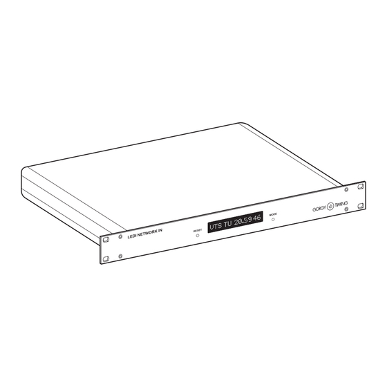
  • Page 16: Interface Face Avant

    NTP in’rack heure UTC/heure locale 3.1. CONDITIONS aU DéMaRRaGE Au démarrage, l’heure et la date du LEDI Network IN ne sont pas valides et ne sont dons pas affichés. Ainsi, vous voyez les messages suivant : ► Quand l’appareil démarre, tous les points de l’afficheur sont allumés.
  • Page 17: Affichage De L'heure

    : 3.2. affICHaGE DE L’HEURE Quand aucune alarme n’est activée et que le LEDI Network IN est correctement synchro- nisé sur un serveur, l’heure actuelle du serveur est affichée en permanence. L’écran affiche alternativement l’heure et la date comme montré ci-dessous : •...
  • Page 18: Conditions D'alarmes Mineures

    L’unique alarme mineure indique que le serveur actuellement utilisé pour la synchronisa- tion ne répond pas (ou pas correctement). Dans ce cas, le LEDI Network IN essaie d’autres serveurs, et l’afficheur indique alternativement l’heure (comme décrit dans la partie précé- dente) et les informations suivantes : 3.5.
  • Page 19: Interface Web

    Dans le dernier cas, vous devez installer la JVM (voir Common\java sur le CDROM). 6: Si vous avez configuré votre LEDI Network IN en mode DHCP et que votre serveur enregistre automatiquement l’identificateur DHCP dans le DNS, vous pouvez entrer le nom DHCP au lieu de l’adresse IP 7/ Vérifiez en particulier la configuration de votre navigateur WEB.
  • Page 20: Description De L'interface Web

    4.2. DESCRIPTION DE L’INTERfaCE WEB 4.2.1. Ecran Principal Voici l’écran qui doit apparaître lorsque vous accédez au sit WEB du LEDI Network IN. Les quatre premiers boutons à gauche de l’écran permettent d’accéder aux panneaux suivants: Standard: informations concernant le produit et configuration des paramètres ré- seau.
  • Page 21: Réglages Standards

    3 minutes après, les sorteis sont désactivées. Voici les différents paramètres: ► IP mode Indique si le LEDI Network IN fonctionne en adresse IP fixe (entrée dans le champs IP address) ou avec le protocole DHCP (l’identificateur DHCP est entré dans le champs DHCP identifier). MDE-LEDI-NETWORK-IN-4065V1.0...
  • Page 22 Chaque numéro s’étend de 0 à 255. DHCP identifier ► Identificateur utilisé quand le LEDI Network IN est configuré en mode DHCP. Il est composé d’au maximum 8 lettres. Sa valeur par défaut est CRnnnnnn (où nnnnnn est le numéro de série sur 6 chiffres).
  • Page 23  DescriptionCourte description du logiciel fonctionnant sur le produit. ► Firmware  Version/Release Date Version du logiciel fonctionnant sur le LEDI Network IN et la date du dernier logi- ciel produit (au format anglais yymmdd, par exemple 021010 pour le 10 Octobre 2002). ►...
  • Page 24: Configuration Snmp

    Quand vous cliquez sur le bouton SNMP, les paramètres SNMP sont affichés ainsi : Le protocole SNMP standardisé fournit un moyen de récupérer des informations et des alarmes du LEDI Network IN. L’accès à ces informations (la MIB) peut être “protégé”...
  • Page 25 ► System name Un nom que vous pouvez donner au LEDI Network IN. Ce nom apparaît dans la variable sysName de la branche système de la MIB. La valeur initiale est LediNt- pRacknnnnnn (où nnnnnn est le numéro de série du produit).
  • Page 26: Configuration Ntp

    Quand vous cliquez sur le bouton NTP, la configuration de la synchronisation du LEDI Network IN est affichée comme ci-dessous: Le LEDI Network IN peut être synchronisé sur trois serveurs NTP au plus. En réalité, le logiciel client NTP n’utilise qu’un seul serveur à la fois, mais peut commuter sur un autre serveur s’il n’y a pas ou trop peu de réponses.
  • Page 27 La partie gauche de l’écran NTP vous permet de configurer le mode de synchronisation et les serveurs NTP utilisés: Si vous sélectionnez la case Auto-detection, le LEDI Network IN essai d’utiliser les ser- veurs GT NTP présents sur votre réseau et d’avoir le mode de synchronisation le plus approprié.
  • Page 28: Configuration Des Sorties

    Ce panneau montre une vue synthétique des sorties du produit. Chaque sortie est pi- lotée par une carte de sortie. L’affichage est considéré comme une sortie et est pilotée par une carte d’affichage. Un LEDI Network IN peut contenir jusqu’à 4 cartes de sortie en plus de la carte d’affichage.
  • Page 29: Configuration De La Sortie Standard

    INTERfaCE WEB CONfIGURaTION DE La SORTIE STaNDaRD Chaque carte de sortie peut-être configurée grâce aux paramètres suivant: ► Vous pouvez désactiver la carte de sortie. Quand une carte est désactivée, le code horaire n’est plus généré en sortie. Pour désactiver la sortie, cochez la case Deac- tivate output.
  • Page 30: Interface Snmp

    INTERfaCE SNMP 5.1. PRéSENTaTION Le LEDI Network IN fournit une interface SNMP v1 pour la surveillance et le diagnostique. Le protocole SNMP permet la supervision d’un appareil par le réseau. Deux types d’infor- mations sont disponibles par l’interface SNMP : ►...
  • Page 31: Structure De La Mib Privée Pour Le Ledi Network In

    ► ntpCliHeader Une courte description du produit. Il est du type GT LEDI Network IN client nnnnnn vxx.yy (aammjj) où xx.yy est la version courante du logiciel, aammjj est la date d’émission du logiciel (jj/mm/aa) et nnnnnn est le numéro de série du produit.
  • Page 32 Numéro de série sur 6 chiffres. ntpCliMAC ► Adresse matérielle de l’interface Ethernet du LEDI Network IN. Cette adresse est de la forme aa:bb:cc:dd:ee (6 octets binaires). ► ntpCliMessageString Description du dernier “trap” généré. Ce texte est lié au trap.
  • Page 33 (Serveur gorgy Timing seulement) Un numéro définit par l’utilisateur qui indique le rang de ce serveur. Quand l’auto-détection est activée, le LEDI Network IN utilise le serveur de plus haut rang. HaRDWaRE La MIB décrit les cartes détectées et leurs configurations. Toutes les cartes de sortie et l’afficheur sont connectés au même bus de sortie.
  • Page 34 ► ntpOutBusCardIndex Index de cette entrée (adresse de la carte). Cette valeur peut prendre la valeur 1 à 8 pour une carte de sortie et 9 pour l’afficheur. ntpOutBusCardState ► L’état de la carte. Il peut être detected pour indiquer que la carte fonctionne correctement, failure si la carte ne répond pas ou scrambled si la réponse de la carte est incorrecte.
  • Page 35: Annexe A - Connexions

    aNNExE a – CONNExIONS Cette annexe contient une description des différents connecteurs du LEDI Network IN. Toutes les prises sont localisées à l’arrière du produit. Actuellement, seuls deux types de sorties sont disponibles. 1. CONNExION POUR TOUS LES PRODUITS 1.1. Produits 230V et 115V AC (type ‘0’) L’arrière du produit possède une prise d’alimentation standard, une prise Ethernet RJ45 et un bouton RESET comme ci-dessous: 1.2.
  • Page 36: Sortie Pour Carte Type 'B' (Sortie Double Afnor/Irig-B Nfs87500)

    2. SORTIE POUR CARTE TYPE ‘B’ (SORTIE DOUBLE AFNOR/IRIG-B NFS87500) Cette carte a sa sortie sur une simple prise 4 points. Le code AFNOR est disponible en double sur cette sortie. Voici une vue schématique de la carte de sortie AFNOR/IRIG-B: AFNOR/IRIG-B sortie 1 Modulateur d’amplitude...
  • Page 37: Sortie Pour Carte Type 'A' (Ascii+Top)

    aNNExE a – CONNExIONS 3. SORTIE POUR CARTE TYPE ‘A’ (ASCII+TOP) Cette carte possède une prise 4 points et un connecteur DB9 La prise 4 points sort le TOP de deux manières différentes et la prise DB9 fournit la trame horaire en sortie en niveau RS-232 ou RS-485.
  • Page 38 Le connecteur DB9 a le format suivant: MDE-LEDI-NETWORK-IN-4065V1.0...
  • Page 39: Annexe B - Format Du Code De Sortie

    aNNExE B – fORMaT DU CODE DE SORTIE Cette annexe contient une description du code horaire utilisé pour les différentes sorties. 1. CARTE TYPE ‘A’ (SORTIE ASCII+TOP) Voici la configuration par défaut : ► La pulsation PPS est générée toutes les 30 secondes et dure 1 seconde. ►...
  • Page 40: Carte Type 'B' (Afnor/Irig-B Nfs87500)

    2. CARTE TYPE ‘B’ (AFNOR/IRIG-B NFS87500) 2.1. Format de la trame MDE-LEDI-NETWORK-IN-4065V1.0...
  • Page 41: Encodage Des Bits

    aNNExE B – fORMaT DU CODE DE SORTIE 2.2. Encodage des bits MDE-LEDI-NETWORK-IN-4065V1.0...
  • Page 42: Annexe C - Caractéristiques

    aNNExE C – CaRaCTéRISTIqUES 1. DIMENSIONS Le rack est au format standard 19” 1U rack. voici ses dimensions: 424 mm 1U = 44 mm 263 mm 482 mm 2. SPéCIfICaTIONS éLECTRIqUES Maximum: 0,1 A max. 230 V AC Typique : 20 mA plus 2mA par sortie Maximum : 0,2 A max.
  • Page 43: Annexe D - Guide Des Codes Produits

    Pour courant alternatif 230V 50Hz Identification du produit LEDI Network IN Par exemple, le code 9257/9AB identifie un LEDI Network IN avec une alimentation cou- rant continu 18/72V et deux sorties. La première sortie utilise le protocole ASCII, la secon- deest une sortie IRIG-B/AFNOR.
  • Page 44: Annexe E - Documents Complémentaires

    aNNExE E – DOCUMENTS COMPLéMENTaIRES Cette annexe contient quelques documents utiles pour gérer un ensemble de pro- duits GT dans vote installation. Chaque document est une table que vous pouvez librement copier et distribuer: ► Description de l’installation: vous pouvez utiliser cette table pour créer une vue synthétique de toute votre installation.
  • Page 45 aNNExE E – DOCUMENTS COMPLéMENTaIRES Vue résumée de l’installation Description de l’installation Date d’installation Nom de l’installateur Description du produit Numéro de série Localisation MDE-LEDI-NETWORK-IN-4065V1.0...
  • Page 46 aNNExE E – DOCUMENTS COMPLéMENTaIRES Configuration des appareils Description de l’installation Date d’installation Nom de l’installateur Fuseau horaire et politique Appareil Sortie de changement d’heure MDE-LEDI-NETWORK-IN-4065V1.0...
  • Page 47 NOTES MDE-LEDI-NETWORK-IN-4065V1.0...
  • Page 48: Support Technique

    RADIO TIMING®, LEDI ®, LEDI CA®, HANDI ® sont des marques déposées GORGY TIMING. Numéro de déclaration d’activité de prestataire de formation : 82 38 04877 38 GORGY TIMING RC 74 B 38 - Toutes modifications d'ordre technique ou esthétique peuvent être apportées sans préavis. MDE-LEDI-NETWORK-IN-4065V1.0...
  • Page 49 USER GUIDE LEDI NETWORK IN ® MDE-LEDI-NETWORK-IN-4065V1.0...
  • Page 50 (keep the distance of a few centimeters). Gorgy Timing disclaims all responsibility in case of accident or damage caused by an improper use of the product. GORGY TIMING products are compliant with the following standards: CE, EN 60950, EN 55022, EN 50024 MDE-LEDI-NETWORK-IN-4065V1.0...
  • Page 51 4.3.2 NTP setup Description ..................... 80 SNMP INTERfaCE ...................... 82 5.1. Presentation ........................82 5.1.1. Structure of the private MIB for LEDI Network IN ........... 83 5.1.2. Description of the SNMP traps ................87 5.2. SNMP interface for NTP server card .................. 88 5.2.1.
  • Page 52 aPPENDIx a – CONNECTIONS ..................93 1. Connection for all products ....................93 1.1. 230V and 115V AC product (type ‘0’)................. 93 1.2. 18/72V DC product (type ‘9’) ..................93 2. Dual AFNOR/IRIG-B NFS87500 output (‘B’ type)..............94 3. Dual AFNOR/IRIG-B NFS87500 DCLS RS422 and TTL output (‘T’ type) ......95 4.
  • Page 53: Introduction

    INTRODUCTION This document is a user’s guide for the LEDI Network IN. This product is a NTP client. The purpose of this device is to synchronize various equipments using a reference time from one or several NTP servers. You can see this product as a kind of converter that translates a “NTP signal”...
  • Page 54: Connect The Product

    IP addresses may be incom- patible with other devices on the network. 1/ For example, you may not have the possibility to configure the LEDI Network IN from a WEB navigator MDE-LEDI-NETWORK-IN-4065V1.0...
  • Page 55: Output Cards Configuration

    The NTP client software is the very heart of the LEDI Network IN. It performs all the syn- chronization, the management of the hardware and provides information for the WEB inter- face and the SNMP protocol.
  • Page 56 Heure serveur Dérive nulle Heure serveur Heure client Heure client To perform this synchronization, the NTP client software permanently compares the two clocks and computes the following information: Evolution dans le temps ► Offset: It’s the difference between the time of the server clock and the time of the client clock.
  • Page 57: B/ Network Dialog

    INTRODUCTION B/ Network dialog The real drift and offset of the LEDI Network IN clock related to the NTP server are es- timated from a measured offset. This offset is computed by subtracting the client clock date from the server clock date.
  • Page 58: The Ntp Client Software

    The software is starting, it initializes and check the hardware if needed. ► auto-detection: Server auto-detection is activated. The NTP client tries to find Gorgy Timing ser- vers. At least one detected server is required to leave this state; ►...
  • Page 59: Full Setup

    2.1. NETWORK CONfIGURaTION 2.1.1. Default configuration The LEDI Network IN is configured to automatically take an IP address from a DHCP server. At startup, the product broadcast a DHCP query to get an IP address. This query contains a DHCP name. There are two cases: ►...
  • Page 60 ► The GTNetMng tool displays automatically the Gorgy Timing products installed on your network. Each line contains information about one connected product as shown below: Name, serial number network mask MaC address DHCp identifier Current Ip address and localization ►...
  • Page 61: Integration In Your Network

    DHCP identifier. Then, you can access to the device from your WEB or SNMP browser. For example if you give the DHCP name ntpin3 to your LEDI Network IN, you can simply type ntpin3 in the address field of your WEB browser.
  • Page 62: Output Cards Configuration

    2.2. OUTPUT CaRDS CONfIGURaTION 2.2.1. Introduction Your LEDI Network IN is provided with up to 4 output cards. Each output card is tightly synchronized on the NTP time code received from the NTP server. Each card acts as a kind of translator that receives time from the NTP software and output specific time code.
  • Page 63: Ntp Server Output Card Configuration

    2.2.4. NTP server output card configuration You can add a NTP server output card to your LEDI network IN. By this way, you can synchronize your local network on this card, which is itself synchronized by the NTP client on a remote Internet NTP server.
  • Page 64: Front Display Interface

    UTC and LOCaL time display 3.1. STaRT-UP CONDITIONS During start-up, the time and date of the LEDI Network IN are not valid and are not dis- played. Then, you can see the following texts: ► When the device start, all the dots of the displays are lightened.
  • Page 65: Time Display

    LEDI Network IN enters learning stage and displays the following text: 3.2. TIME DISPLaY When no alarm is present and the LEDI Network IN is correctly synchronized on a server, the current time of the server is permanently displayed. The display alternatively shows time and date as shown below: ►...
  • Page 66: Alarm Condition

    The commuting alarm indicates that the server currently used for synchronization does not reply (or does not reply correctly). In this case, the LEDI Network IN tries another server. The display alternatively shows time (as described in previous part) and the following text:...
  • Page 67: Web Interface

    3. You don’t have a JVM engine installed on your computer. For the first two reasons, you have to check for the IP address of the LEDI Network IN and your network configuration. For the last reason, you have to install the JVM (see directory Common\JAVA on the CDROM).
  • Page 68: Description Of The Web Interface

    NTP: diagnostic and configuration of the NTP software behavior; Output: diagnostic and configuration of output cards and display. The Set Up! button updates immediately the LEDI Network IN configuration. The confi- guration is stored permanently in an EEPROM. WARNING. Some parameters cannot be modified without restarting the LEDI Network IN.
  • Page 69: Standard Setup

    Here are the different parameters: ► IP mode Indicate if the LEDI Network IN works with a fixed IP (set in the field IP address) or use DHCP protocol (the DHCP identifier is set in the field DHCP identifier); MDE-LEDI-NETWORK-IN-4065V1.0...
  • Page 70: Product Information

    Each number range from 0 to 255; DHCP identifier ► Identifier to be used when the LEDI Network IN is configured in DHCP mode. This identifier has 8 letters maximum. The default value is CRnnnnnn (where nnnnnn is the serial number on 6 digits);...
  • Page 71: Status Bar

    A text that Indicates why the LEDI Network IN has restarted the last time. WEB SITE aCCESS PROTECTION If you want to protect access to the parameters of the LEDI Network IN, you can specify a password. This is done by enter the password twice in the area Enter password and Confirm password (the same password in the two areas).
  • Page 72: Snmp Setup

    When you click the SNMP button, the SNMP parameters are displayed as shown below: The very standardized SNMP protocol provides a means to get information and alarms from the LEDI Network IN. Access to these information (the MIB) can be “protected” by a keyword that is the Community Name.
  • Page 73 ► System name A text that you can use to give a name to the LEDI Network IN. This name appears in the sysName variable of the system branch of the MIB. The initial value is Ledi- NetwkINnnnnnn (where nnnnnn is the serial number of the product);...
  • Page 74: Ntp Setup

    When you click the NTP button, the configuration of the synchronization of the LEDI Network IN is displayed as shown below: The LEDI Network IN can be synchronized on up to three NTP servers. In fact, the NTP software uses only one server at the same time but can commute to another server when there is no or not enough reply.
  • Page 75 The left part of the NTP screen allows you to configure the synchronization mode and the NTP servers used: If you select the checkbox Auto-detection, the LEDI Network IN try to use the GT NTP servers present on your network and use the more appropriate synchronization mode.
  • Page 76: Output And Display Setup

    This panel shows a synthetic view of the outputs of the product. The display is conside- red as an output and is driven by a display card. A LEDI Network IN can contain up to 4 output cards plus the display card.
  • Page 77 WEB INTERfaCE STaNDaRD OUTPUT CONfIGURaTION Description & name of the card Disable the output DST policy Offset to apply to UTC time The previous picture shows the configuration panel for an AFNOR/IRIG-B. In addition, the description contains identification and version of the program embedded in the out- put card (there, it’s the program NTPSAFN1, version 0252).
  • Page 78 Here are the different DST policies : Start: Last Sunday in March at 1 am UTC European Union End: Last Sunday in October at 1 am UTC USa / Canada / Mexico tart: First Sunday in April / St. Johns / Bahamas / End: Last Sunday in October Turks / Caicos Start: Last Sunday in October...
  • Page 79: Web Interface Of Ntp Server Output Card

    To configure network and SNMP parameters, the NTP server output card provides the same WEB panels than the LEDI Network IN (see below). Please refer to parts 2.2 and 2.3 for more details. The NTP server MIB is detailed in page 40.
  • Page 80: Ntp Setup Description

    4.3.2 NTP setup When you click the NTP button, the configuration of the NTP server software of the output card is displayed as shown below: Description Here is the short description of the different fields: ► STRATUM level the stratum value to be stored in the NTP messages sends to the NTP clients. ►...
  • Page 81 WEB INTERfaCE ► When not synchronized Define the effect on some NTP fields when the LEDI Network Enhanced is not synchronized . The possible values LI&STRATUM unchanged, STRATUM=0,LI un- changed, STRATUM unchanged, LI=3(11b), STRATUM=0, LI=3(11b) ► RFC868 compatibility Specify the kind of compatibility with RFC868 : Not compatible, UDP Time server or TCP Time server ►...
  • Page 82: Snmp Interface

    SNMP INTERfaCE 5.1. PRESENTaTION The LEDI Network IN provides a SNMP v1 interface for fine monitoring and diagnostic. The SNMP protocol allows the supervision of a device through the network. Two kind of information are available through a SNMP interface: ►...
  • Page 83: Structure Of The Private Mib For Ledi Network In

    ► ntpCliHeader A short description of the product. It should be something like GT LEDI Network IN client nnnnnn Vxx.yy (yymmdd) where xx.yy is the current version of the software, yymmdd is the release date of the software (dd/mm/yy) and nnnnnn is the serial number of the product.
  • Page 84 Serial number of this product on 6 digits. ► ntpCliMAC Hardware address of the Ethernet interface of the LEDI Network IN. This address is on the form aa:bb:cc:dd:ee (6 binary bytes). ► ntpCliMessageString A text that gives the description of the last generated trap. This text is also attached to the trap.
  • Page 85 Load of the server (average number of requests per second) as returned during auto-detection stage. ► ntpCliSyncSrvPrefered (Gorgy Timing server only) A number that indicates a user-defined rank attached to this server. When auto-de- tection is activated, the LEDI Network IN takes the server with higher rank. MDE-LEDI-NETWORK-IN-4065V1.0...
  • Page 86 HaRDWaRE The MIB describes which card is detected and what is the configuration for the cards. All the output cards and the display are connected to a same output bus. The different fields of this branch are described below: ► ntpOutBusCardNumber Number of cards detected on output bus.
  • Page 87: Description Of The Snmp Traps

    SNMP INTERfaCE ► ntpOutBusCardactivation: Indicate if the output of the card activated or deactivated (this feature can be controlled from the WEB interface). If the card cannot be deactivated, this field has the value notapplicable; ntpOutBusCardTimezone: ► Time-zone for this output. This is displayed as an offset from universal time. This setting can be changed from the WEB interface;...
  • Page 88: Snmp Interface For Ntp Server Card

    The NTP server card provides its own a SNMP v1 interface for fine monitoring and diagnos- tic. Its private MIB is described in the file GtNtpServer.mib provided on the CDROM in the directory English\LEDI Network IN\MIB. Localization in the MIB: iso(1).org(3).dod(6).internet(1).private(4).enterprises(1).gorgy(8955).software(1).ntpSrv(3)
  • Page 89: General Information

    SNMP INTERfaCE GENERaL INfORMaTION ntpSrvHeader ► Short description of the NTP server output card. ► ntpVersionNumber Version and release date of the NTP server firmware ► ntpSrvSerialNumber Serial number of the Ethernet interface (unique for each device) ► ntpSrvMaC Address of the Ethernet interface (MAC address) ntpSrvMessageString ►...
  • Page 90 ► ntpSrvRescaling true(1) if the NTP server software is currently rescaling on the hardware. During rescaling stage, the NTP server don’t reply to clients false(0) if no rescaling in progress ► ntpSrvRequiredAccuracy A text that gives the required accuracy for this NTP software (related to the time provided by the hardware) unit: seconds NTP server outcard: this accuracy is fixed to 0.24414 ms (4096-1 s)
  • Page 91 SNMP INTERfaCE ExTERNaL SYNCHRONISaTION INfORMaTION It gives information on an external time reference used by the hardware (for example an antenna). ► ntpSrvExternallySynchronized notapplicable(2) if there is no information on external time reference true(1) if the hardware is correctly synchronized on its external time reference false(0) if the hardware is not synchronized on its external time reference (out of radio coverture?) ►...
  • Page 92: Description Of The Snmp Traps

    5.2.2. Description of the SNMP traps Related MIB variable Alarm meaning ntpSrvAutonomy Warning: no time code. The time base has less than 3 minutes of autonomy ntpSrvFailure Failure: no more time code and the time base has no more autonomy ntpSrvRescaled NTP server software is rescaled or is resca- ntpSrvRescaling...
  • Page 93: Appendix A - Connections

    aPPENDIx a – CONNECTIONS This appendix contains a description of the different connectors of the LEDI Network IN. All the plugs are localized on the backside of the product. 1. CONNECTION fOR aLL PRODUCTS 1.1. 230V and 115V AC product (type ‘0’) The backside of the product has a standard power supply plug, the Ethernet RJ45 plug and a RESET button as shown below: 1.2.
  • Page 94: Dual Afnor/Irig-B Nfs87500 Output ('B' Type)

    2. DUAL AFNOR/IRIG-B NFS87500 OUTPUT (‘B’ TYPE) This card has its output on a single 4 points plug. The AFNOR code is available twice on this output. Here is a schematic overview of the AFNOR/IRIG-B output card: AFNOR/IRIG-B output 1 Amplitude Modulator Time code...
  • Page 95: Dual Afnor/Irig-B Nfs87500 Dcls Rs422 And Ttl Output ('T' Type)

    aPPENDIx a – CONNECTIONS 3. DUaL afNOR/IRIG-B NfS87500 DCLS RS422 aND TTL OUTPUT (‘T’ TYPE) This card has its outputs on a 4 points plug and a BNC connector. The RS422 AFNOR code is available on the 4 points output : Tx/Rx + Tx/Rx - The BNC connector provides TTL signal :...
  • Page 96: Rs232 And 485/422 Ascii+Top ('A' And 'R' Type)

    4. RS232 AND 485/422 ASCII+TOP (‘A’ AND ‘R’ TYPE) The ASCII+TOP card has a 4 points plug and a DB9 connector. The 4 points plug is used to output the TOP through static relays and the DB9 plug is used to output time frame using RS-232 levels.
  • Page 97: Top / Alarm Output ('A', 'R' Type And 'G' Type)

    aPPENDIx a – CONNECTIONS 5. TOP / ALARM OUTPUT (‘A’, ‘R’ TYPE AND ‘G’ TYPE) 5.1. Pin-out The 4 points plug on the ASCII and ALARM cards can provide a configurable time TOP or synchro/power alarm TOP. The 4 points plug has the following pin-out: static relay output 1 open collector output Static Relay Outputs 1 and 2 :...
  • Page 98: Examples Of How To Use The Open Collector Output (Pins 3-4)

    Here are some examples of how to use this output : 5.2. Examples of how to use the open collector output (pins 3-4) General case : loudspeaker External WaRNING : VDC max = 45 Volts Power ► You need to add R if the load (LED, loudspeaker,…) does not accept the VDC voltage.
  • Page 99: Example Of How To Use The Static Relay Output (Pins 1-2)

    aPPENDIx a – CONNECTIONS 5.3. Example of how to use the static relay output (pins 1-2) loudspeaker External WaRNING : V max = 60 Volts DC or AC pulse Power Supply < WARNING : You must ensure that MDE-LEDI-NETWORK-IN-4065V1.0...
  • Page 100: Appendix B - Output Code Format

    aPPENDIx B – OUTPUT CODE fORMaT This appendix contains a description of the time code used for the different kind of outputs. 1. ‘A’ AND ‘R’ TYPE CARDS (ASCII+TOP OUTPUT) The default configuration is shown below: ► The PPS is generated every 30 seconds and is 1 second long; ►...
  • Page 101: B' And 'T' Type Cards (Afnor/Irig-B Nfs87500)

    aPPENDIx B – OUTPUT CODE fORMaT 2. ‘B’ AND ‘T’ TYPE CARDS (AFNOR/IRIG-B NFS87500) 2.1. frame format MDE-LEDI-NETWORK-IN-4065V1.0...
  • Page 102: Bit Encoding

    2.2. Bit encoding The signal is modulated only on ‘B’ card. The ‘T’ card output signal has TTL level. MDE-LEDI-NETWORK-IN-4065V1.0...
  • Page 103: Dcf And Tdf Time Code Description

    aPPENDIx B – OUTPUT CODE fORMaT 3. DCf aND TDf TIME CODE DESCRIPTION Details of message transmitted over a full minute : "0" synchronization bits 40 80 year control bits month J+1 =JF day of week (1= monday ; 7= sunday) "0"...
  • Page 104: Appendix C - Troubleshooting

    aPPENDIx C – TROUBLESHOOTING This section tries to answer to most frequent question concerning the use of your NTP device. First, ensure that the GTNetManager software and a SUN JAVA Virtual Machine 1.4.2_X are installed on your computer. I MaDE a « SCaN NOW ! » WITH GTNETMaNaGER BUT I CaNNOT SEE THE DEvICE ? ►...
  • Page 105: An Output Is Not Visible In The Configuration Web Page

     YES page reachable, browser unable load Open a TELNET session: Telnet < ip address> 9999 password : gtmt Proceed to a “Factory Default”, then “quit and save”. Refresh the WEB page. aN OUTPUT IS NOT vISIBLE IN THE CONfIGURaTION WEB PaGE ? ►...
  • Page 106: Appendix D - Maintenance

    D – MaINTENaNCE 1. PROCEDURE TO fOLLOW TO CHaNGE THE BaTTERY Tools : Screw Driver ► Gorgy Timing reference : BaT1728S ► ► Life period : 5 years BaTTERY CHECKING ► Connect the product to the 230VAC during one hour.
  • Page 107: Output Card Switchs Verification

    3. UPDaTING fIRMWaRE 3.1. Obtaining Firmware Firmware updates and releases notes for GORGY TIMING NTP devices can be down- loaded directly from GORGY TIMING WEB site (www.ntp-secured-solutions.com). This tool only runs on a PC running Windows 98, NT, 2000 or XP.
  • Page 108: Reloading Firmware

    3.2. Reloading Firmware Download the update executable and run it from your computer or execute it directly from the WEB site. The following window appears at the screen : short description of the update It uses by default the temporary To change the directory used to store directory defined on your PC temporary file, click on this button...
  • Page 109 The product to update must be accessible through your network from the PC used to run GTUpdate ► check that the IP address is valid, compatible with those of your PC and that it’s really the address of a Gorgy Timing product ► Check that the product to update is powered. ☛...
  • Page 110: Appendix E - Data

    aPPENDIx E – DaTa 1. MEaSUREMENTS The rack is a standard 19” 1U rack. Here are its dimensions: 424 mm 1U = 44 mm 263 mm 482 mm 2. SPECIfICaTIONS Maximum: 0,1 A max. 230 V AC Typical : 20 mA plus 2mA per output Maximum : 0,2 A max.
  • Page 111: Stamp Contents

    DCLS AFNOR & IRIG B (TTL / RS 422) Ó ELECTRONIC BOARD TROPICALIZED Ó For example, the 9257/9AB code identify a LEDI Network IN with 18/72V Direct Current power supply and two outputs. The first output uses the ASCII protocol, the second one uses the IRIG-B/AFNOR output. MDE-LEDI-NETWORK-IN-4065V1.0...
  • Page 112: Appendix F - Additional Documents

    aPPENDIx f – aDDITIONaL DOCUMENTS This appendix contains some documents that can be useful to manage a set of GT products in your installation. Each document is a table that you can freely copy and distribute: ► Installation description: you can use this table to make a synthetic view of all your installation.
  • Page 113 Summarized installation view Installation description Installation date Who has done this installation Device description Serial number Localization MDE-LEDI-NETWORK-IN-4065V1.0...
  • Page 114 Devices configuration Installation description Installation date Who has done this installation Device Output Time Zone&DST configuration MDE-LEDI-NETWORK-IN-4065V1.0...
  • Page 115 NOTES MDE-LEDI-NETWORK-IN-4065V1.0...
  • Page 116: Technical Support

    +33 476 30 48 20 support@gorgy-timing.fr RADIO TIMING®, LEDI®, LEDICA®, HANDI® are trademarks by GORGY TIMING. Number of statement for training provider activity : 82 38 04877 38 Gorgy Timing RC74B38 - Any technical, aesthetic, color modifications can be made without notice. MDE-LEDI-NETWORK-IN-4065V1.0...

Table des Matières