
Manuels Connexes pour Horizon Hobby STAUFENBIEL HAWK III REVOLUTION HSF0314093 PNP


Sommaire des Matières pour Horizon Hobby STAUFENBIEL HAWK III REVOLUTION HSF0314093 PNP
- Page 1 MONTAGEANLEITUNG INSTRUCTION MANUAL INSTRUCTIONS DE MONTAGE HSF0314093 / HSF0314093P...
-
Page 2: Sicherheitshinweise
SICHERHEITSHINWEISE WARNUNG: Lesen Sie die GESAMTE Bedienungsanleitung, um sich vor Inbetriebnahme mit den Funktionen des Produkts vertraut zu machen. Eine nicht ordnungsgemäße Bedienung des Produkts kann das Produkt und persönliches Eigentum schädigen und schwere Verletzungen verursachen. Dies ist ein hoch entwickeltes Produkt für den Hobbygebrauch. Es muss mit Vorsicht und Umsicht bedient werden und erfordert einige mechanische Grundfähigkeiten. -
Page 3: Technische Daten
TECHNISCHE DATEN 1700 mm (67 in) 1700 mm (67 in) 900 mm (35 in) 23,5 dm² (364.3 in²) 1350 g (48 oz) ZUBEHÖR PNP-VERSION ARF-VERSION Eingebaut: Benötigt: X-Max X36 L-800 X-Max X36 L-800 (3x) DS 1550 MG (3x) DS 1550 MG CAM Carbon 12x8“... -
Page 4: Lieferumfang
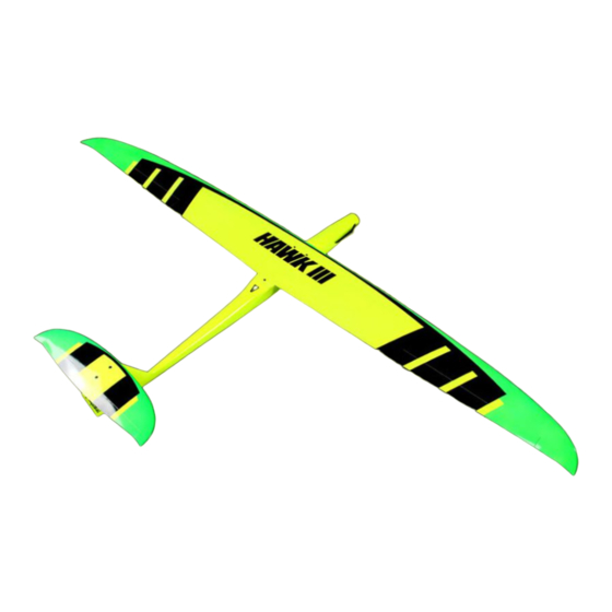
HAWK III um die mittlerweile dritte Version des beliebten F5B-Hotliners aus dem Hause Horizon Hobby. Das Modell wurde im Vergleich zum Vorgänger an diversen Stelle mit CFK verstärkt; zudem verfügt es nun serienmäßig über Kühlungsschlitze und einen Luftauslass. Für ein neutrales Flugverhalten wurde die EWD auf 0°... - Page 5 DER RUMPF NUR ARF VERSION: Montieren Sie zum Anpassen zunächst vor- läufig das Höhenleitwerk. Dabei kommt die längere M3-Senkkopfschraube in das vorde- re Loch. NUR ARF VERSION: Markieren Sie auf dem Höhenruder nun die Mitte des Rumpfes. NUR ARF VERSION: Fräsen Sie ein Schlitz passend zum beiliegen- den GFK-Ruderhorn gemäß...
- Page 6 NUR ARF VERSION: Entfernen Sie mit einem Fräser oder kleinen Seitenschneider zur leichteren Montage die beiden Haltelaschen am Höhenruderservo. NUR ARF VERSION: Verschrumpfen Sie das Servo komplett und schleifen Sie es mit grobem Schleifpapier beidseitig gut an. NUR ARF VERSION: Stutzen Sie das Servohorn, sodass lediglich das innere Loch stehen bleibt.
- Page 7 NUR ARF VERSION: Fertigen Sie ein Servo-Verlängerungskabel mit einer Länge von 45cm und verbinden Sie dieses mit dem Servo. Wir empfehlen die Ver- wendung von Tape oder einem Safety Clip zur Sicherung. NUR ARF VERSION: Fräsen Sie für die Höhenruderanlenkung eine Öffnung in das Seitenleitwerk.
- Page 8 NUR ARF VERSION: Montieren Sie nun erneut das Höhenleitwerk (wie oben beschrieben) und fädeln Sie das Anlenkgestänge durch das GFK-Ruderhorn. Richten Sie anschließend das Servo im Rumpf aus, sodass bei neutralem Servohorn die Ruderfläche ebenfalls in Neutralstellung ist. Fixieren Sie das Servo erneut mit einer Montageklemme und lassen Sie den Kleber aushärten.
- Page 9 Die Lötstellen werden anschließend mit Schrumpfschlauch isoliert und platzsparend mit einem Kabelbinder am Motor fixiert, so- dass der Regler idealerweise direkt hinter dem Motor liegt. Fädeln Sie Motor und Regler durch den Rumpf und verschrauben Sie den Motor (Loc- tite verwenden). Montieren Sie Spinner und Luftschraube.
- Page 10 DIE TRAGFLÄCHE NUR ARF VERSION: Die folgenden Beschreibungen beziehen sich auf beide Querruder, werden bildlich jedoch nur auf einer Seite gezeigt. Verschrauben Sie das Messing-Rudernhorn mit Loctite in den Querrudern. NUR ARF VERSION: Entfernen Sie mit einem Fräser oder kleinen Seitenschneider die beiden Haltelaschen an den Querruderservos.
- Page 11 NUR ARF VERSION: Fertigen Sie zwei Servoverlängerungskabel mit jeweils 45cm Länge und verbinden Sie diese mit den Servos. NUR ARF VERSION: Fädeln Sie die Verlängerungskabel durch die Tragfläche. Um den Aufbau des Modells zu erleichtern, empfehlen wir eine weitere Steckverbindung auf Basis von MPX Steckern zwischen Trag- fläche und Empfänger zu fertigen.
-
Page 12: Der Schwerpunkt
Verkleben Sie die Schachtabdeckungen mit UHU Por (Kontaktkleber!). So können die Ab- deckungen später wieder leicht demontiert werden. Verschrauben Sie die Tragfl ächen mit den bei- liegenden Schrauben mit dem Rumpf. Im letzten Schritt markieren Sie den Schwer- punkt des Modells auf der Unterseite der Tragfl äche gemäß... - Page 13 RUDERAUSSCHLÄGE Die Montagearbeiten sind nun abgeschlossen und es kann mit der Senderprogrammierung be- gonnen werden. Überprüfen Sie nochmals die Laufrichtung aller Servos. Bitte entnehmen Sie die Ruderausschläge sowie den genauen Schwerpunkt der Tabelle. Zum Landen sollten die Querruder als Bremsklappen hochgestellt werden. Je nach Ausschlag muss etwas Tiefenruder beigemischt werden.
- Page 14 KONFORMITÄTSERKLÄRUNG Horizon Hobby GmbH erklärt hiermit, dass dieses Produkt konform zu den essentiellen Anforderungen der EMC Direktive. Eine Kopie der Konformitätserklärung ist online unter folgender Adresse verfügbar : http://www.horizonhobby.com/content/support-render-compliance HINWEISE ZUM UMWELTSCHUTZ Dieses Produkt darf nicht mit anderem Abfall entsorgt werden. Stattdessen obliegt es dem Benut- zer, das Altgerät an einer designierten Receycling-Sammelstelle für elektrische und elektronische...
-
Page 16: Safety Precautions And Warnings
WARNING WARNING: Read the ENTIRE instruction manual to become familiar with the features of the product before operating. Failure to operate the product correctly can result in damage to the product, personal property and cause serious injury. This is a sophisticated hobby product. It must be operated with caution and common sense and requires some basic mechanical ability. -
Page 17: Accessories
SPECIFICATIONS 1700 mm (67 in) 1700 mm (67 in) 900 mm (35 in) 23,5 dm² (364.3 in²) 1350 g (48 oz) ACCESSORIES PNP-VERSION ARF-VERSION Bulit-in: Needed: X-Max X36 L-800 X-Max X36 L-800 (3x) DS 1550 MG (3x) DS 1550 MG CAM Carbon 12x8“... - Page 18 PREFACE Gratulation for your new HAWK III. This is the third version of the famous F5B Hotliner from Staufenbiel. The fuselage is now reinforced with Carbon and got air in and outlets. For a better visibility the design is changed to Neon. The HAWK III is available in two versions. Several steps in this manual are done in the PNP Version and are only for the ARF Version.
- Page 19 THE FUSELAGE ARF VERSION ONLY: Install temporary the elevator. Use the longer M3 screw for the hole in the front. ARF VERSION ONLY: Mark the center of the fuselage with a felt tip- ped pen on the elevator. ARF VERSION ONLY: Cut a slot for the fiberglass rudderhorn on the marking of the previvous step.
- Page 20 ARF VERSION ONLY: Remove the brackets on the sides of the ser- vos so they fix easier. ARF VERSION ONLY: Shrink the servo and rought it on both sides with sandpaper. ARF VERSION ONLY: Cut the Servohorn to the first hole. Enlarge the hole to 1,5mm.
- Page 21 ARF VERSION ONLY: Assembly the servo extension cable to a lenght of 45cm and connect it to the servo. We recommend to fasten the connection with tape or a Safety clip. ARF VERSION ONLY: Mill the opening for the elevator linkage in the rudder.
- Page 22 ARF VERSION ONLY: Install the elevator (as described above) and route the linkage throught the Fiberglass rud- derhorn. Adjust the servo in the fuselage that elevator controll surface and rudderhorn are both in neutral position. Fix the servo with a wedge and let the glue dry.
- Page 23 Use shrinking tube and fix the cable with a cable strap on the motor. In this arangement the ESC would be direct behind the motor. Install the motor and ESC in the fuselage. Use Loctite. Install the spinner and propeller. Use Velcro tape on the bottom of the fuselage to fix the receiver and battery.
- Page 24 THE WING ARF VERSION ONLY: Please note that the following section is for installing of both aileron servos and linkage. ARF VERSION ONLY: Remove the brackets on the sides of the ser- vos. Set the servos with a servotester to neut- ral and install the servohorn.
- Page 25 ARF VERSION ONLY: Assembly two 45cm servo extension cable and connect them to the servos . ARF VERSION ONLY: Route the extension cable through the wing. For setting up the aircraft on the flying field we recommend to install a MPX connector bet- ween wing and fuselage.
-
Page 26: Center Of Gravity
Glue the servo cover with UHU Por or an equivalent contact glue. This gives you the oportunity to remove the cover later. Secure the wings with the two screws in the fuselage. Mark the CG on the bottom of the wing as shown on the picture and move the battery to adjust the CG. -
Page 27: Control Throws
CONTROL THROWS Please be so kind an check once again the servo direction. Adjust the rudderthrow and the Center of Gravity according to the list. ▲ 10 mm / ▼ 8 mm; 35% Expo Aileron ▲ 5 mm / ▼ 3 mm; 20% Expo Elevator ▲... -
Page 28: Declaration Of Confirmity
DECLARATION OF CONFIRMITY EU Compliance Statement: Horizon Hobby, LLC hereby declares that this product is in compliance with the essential requirements and other relevant provisions of the EMC Directive. A copy of the EU Declaration of Conformity is available online at: http://www.horizonhobby.com/content/support-render-compliance. -
Page 30: Précautions Et Avertissements Liés À La Sécurité
AVERTISSEMENT AVERTISSEMENT: lisez la TOTALITÉ du manuel d‘utilisation afin de vous vous familiariser avec les caractéristiques du produit avant de le faire fonctionner. Une utilisation incorrecte du produit peut ent- raîner sa détérioration, ainsi que des risques de dégâts matériels, voire de blessures graves. Ceci est un produit de loisirs sophistiqué. -
Page 31: Caracteristiques
CARACTERISTIQUES 1700 mm (67 in) 1700 mm (67 in) 900 mm (35 in) 23,5 dm² (364.3 in²) 1350 g (48 oz) ACCESSOIRES VERSION PNP VERSION ARF Installé : Requis : X-Max X36 L-800 X-Max X36 L-800 (3x) DS 1550 MG (3x) DS 1550 MG CAM Carbon 12x8“... - Page 32 PREAMBULE Félicitations pour l‘acquisition de votre HAWK III REVOLUTION. Il s‘agit ici de la troisième version du très apprécié hotliner de Staufenbiel. Par rapport à son prédécesseur, le modèle a reçu des renforts en fi bre de carbone, les ouïes d’aération sont déjà découpées et le calage de l‘aile à été modifi é à 0° pour donner un comportement neutre en vol.
-
Page 33: Uniquement Sur Version Arf
LE FUSELAGE UNIQUEMENT SUR VERSION ARF : Montez provisoirement le stabilisateur. Uti- lisez la vis M3 la plus longue dans le trou avant. UNIQUEMENT SUR VERSION ARF : Tracez un repère du milieu du fuselage sur le stabilisateur. UNIQUEMENT SUR VERSION ARF : Fraisez une fente aux dimensions du guignol en fibre de verre à... - Page 34 UNIQUEMENT SUR VERSION ARF : A l‘aide d‘une mini fraiseuse, supprimez les pattes de fixation du servo de profondeur. UNIQUEMENT SUR VERSION ARF : Emballez la totalité du servo à l‘aide de gaine thermo-rétractable que vous rendrez rugueuse en la ponçant sur tous ses côtés. UNIQUEMENT SUR VERSION ARF : Raccourcissez le palonnier de servo de tel- le sorte que seul le trou le plus proche de...
- Page 35 UNIQUEMENT SUR VERSION ARF : Procédez à la fabrication d‘une rallonge de servos d‘une longueur de 45 cm et reliez la au servo. Nous conseillons l‘emploi de ruban adhésif ou d‘un clip de sécurité. UNIQUEMENT SUR VERSION ARF : Fraisez une ouverture dans la dérive afin de pouvoir mettre en place la commande de pro- fondeur.
- Page 36 UNIQUEMENT SUR VERSION ARF : Remontez maintenant le stabilisateur ( com- me décrit plus haut) et enfilez la commande dans le guignol de profondeur. Puis position- nez le servo encollé de telle sorte qu‘avec le palonnier au neutre, la profondeur le soit également.
- Page 37 Les soudures seront ensuite isolées à l‘aide de gaine thermo-rétractable et serrées sur le moteur à l‘aide d‘un serre câble afin de prendre le moins de place possible. Idéale- ment le variateur sera positionné juste derriè- re le moteur. Enfilez le moteur et le variateur dans le fusela- ge puis vissez le moteur en place.
- Page 38 L‘AILE UNIQUEMENT SUR VERSION ARF : Les explications qui suivent concernent les deux ailerons, même si l‘illustration ne montre qu‘un seul côté. Vissez le palonnier en laiton dans les ailerons en assurant le filetage avec du frein-filet. UNIQUEMENT SUR VERSION ARF : A l‘aide d‘une mini fraiseuse, supprimez les pattes de fixation des servos et placez les servos au neutre puis vissez les palonniers...
- Page 39 UNIQUEMENT SUR VERSION ARF : Fabriquez deux rallonges de servos d‘une longueur de 45 cm chacune et reliez les aux servos. Nous conseillons l‘emploi de ruban adhésif ou d‘un clip de sécurité. UNIQUEMENT SUR VERSION ARF : Enfilez les câbles-rallonges dans les ailes. Afin de simplifier le montage du modèle, nous conseillons d’utiliser une prise multiplex entre l‘aile et le récepteur.
- Page 40 Montez en place les caches de servos à l‘aide de colle UHU Por, ce qui permettra si besoin par la suite de les démonter simple- ment et sans dégâts sur l‘entoilage. Vissez l‘aile au fuselage à l‘aide des vis four- nies.
-
Page 41: Pieces De Rechange
DEBATTEMENTS a r t t n i s é ‘ l t i t a prendre en compte le bon centrage et trouver les débattements conseillés ci-dessous. ▲ 10 mm / ▼ 8 mm; 35% d‘exponentiel Ailerons ▲ 5 mm / ▼ 3 mm; 20% d‘exponentiel Profondeur ▲... -
Page 42: Déclaration De Conformité Ce
AUTEURS DE CETTE NOTICE D‘UTILISATION Texte: M.V. Mise en page: M.P.M Photos: M.V. Traduction: D.A. Horizon Hobby GmbH Hanskampring 9, 22885 Barsbüttel, Deutschland Directeur général:: Joseph M. Ambrose, Chris Dickerson www.horizonhobby.eu Copyright © Horizon Hobby GmbH, 2017... - Page 44 HERAUSRAGENDE SICHTBARKEIT EXCELLENT VISIBILITY OPTIMAL ABGESTIMMTE EWD OPTI. LONGITUDINAL DIHEDRAL CFK-VERSTÄRKTER RUMPF REINFORCED FUSELAGE OPTIMAL GEKÜHLT OPTIMALLY COOLED GROSSE RUMPFÖFFNUNG LARGE FUSELAGE OPENING GFK-LANDEKUFE LANDING SKID KURZE BAUZEIT SHORT ASSEMBLY TIME EINGEBAUTE ELEKTRONIK PRE-INSTALLED ELECTRONICS © 2016 Gustav Staufenbiel GmbH...