Table des Matières
Publicité
Les langues disponibles
Les langues disponibles
Liens rapides
Publicité
Chapitres
Table des Matières

Manuels Connexes pour IFM DTC600


Sommaire des Matières pour IFM DTC600
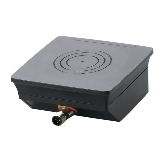
- Page 1 Montageanleitung Installation instructions Notice de montage RF-Identifikationssystem Lese-/Schreibkopf RF identification system Read/write head Système d'identification RFID Tête de lecture / écriture DTC600...
-
Page 2: Table Des Matières
Inhalt 1 Vorbemerkung .....................4 1.1 Verwendete Symbole ..................4 1.2 Verwendete Warnhinweise ................4 2 Sicherheitshinweise .....................4 2.1 Allgemein ......................4 2.2 Funkanlagen ....................5 2.3 Störung elektronischer und medizinischer Geräte ........5 3 Bestimmungsgemäße Verwendung ..............5 4 Funktion .......................6 4.1 Funktionsweise .....................6 4.2 Übersicht ......................6 5 Montage .......................6 5.1 Generelle Montagehinweise .................6 5.2 Hinweise zur ID-Tag Montage ..............7... - Page 3 11 Wartung, Instandsetzung, Entsorgung .............15 12 Zulassungen/Normen ..................16 12.1 Funkzulassungen ..................16 12.1.1 Übersicht ..................16 12.1.2 Europa ....................16 12.1.3 USA ....................16 12.1.4 Kanada .....................16 12.1.5 Australien ..................17 12.2 EU-Konformitätserklärung ................17...
-
Page 4: Vorbemerkung
1 Vorbemerkung Technische Daten, Zulassungen, Zubehör und weitere Informationen → www.ifm.com. 1.1 Verwendete Symbole ► Handlungsanweisung → Querverweis Wichtiger Hinweis Fehlfunktionen oder Störungen sind bei Nichtbeachtung möglich. Information Ergänzender Hinweis 1.2 Verwendete Warnhinweise ACHTUNG! Art und Quelle der Gefahr > Mögliche Folgen sind Sachschäden. -
Page 5: Funkanlagen
Gerät für den Einsatz in Industrieumgebungen bestimmt. Für den Einsatz in Wohnbereichen ist das Gerät nicht geeignet. Das Gerät darf nur unter den im Datenblatt angegebenen Umgebungsbedingungen verwendet werden. 3 Bestimmungsgemäße Verwendung Der Lese-/Schreibkopf DTC600 eignet sich zum berührungslosen Lesen und Schreiben systemkonformer ID-Tags. Die Daten werden über CAN-Bus übertragen. -
Page 6: Funktion
Kopplung. Die integrierte Antennenspule des Lese-/Schreibkopfes erzeugt ein magnetisches Feld, das zu einem Teil die Antennenspule des ID-Tags durchdringt. Durch Induktion wird dort eine Spannung erzeugt, die den Datenträger mit Energie versorgt. 4.2 Übersicht Art.-Nr.: DTC600 Funktion: Lese-/Schreibkopf Typbezeichnung: DTCHF HLRWCOUS03 Arbeitsfrequenz:... -
Page 7: Hinweise Zur Id-Tag Montage
5.2 Hinweise zur ID-Tag Montage Die Montage der ID-Tags in und auf Metall verringert den Lese- und Schreibabstand. Zur Positionierung der ID-Tags sind die Lese-/Schreibköpfe auf der aktiven Fläche mit einem Antennensymbol versehen. Es kennzeichnet die Mitte der integrierten Antennenspule und muss mit der ID-Tag Mitte übereinstimmen. Die Ausrichtung der Achsen des Lese-/Schreibkopfes und der ID-Tag-Spule müssen übereinstimmen. -
Page 8: Montage Mit Befestigungswinkel E80335
5.5.1 Montage mit Befestigungswinkel E80335 Abb. 3: Montage mit Befestigungswinkel E80335 5.5.2 Montage mit Klemmschale E80336 Die Klemmschale dient zur Montage des Gerätes an einen Klemmzylinder. Die folgenden Klemmzylinder können verwendet werden: ● E21110 mit einem Stangen-Durchmesser von 12 mm ●... -
Page 9: Montage Mit Befestigungsstäben E80337
5.5.3 Montage mit Befestigungsstäben E80337 Abb. 5: Montage mit Befestigungstäben E80337 ► Gerät mit Befestigungs schrauben am vorgesehenen Montageort befestigen. 5.6 Montageabstände Abb. 6: Montageabstände Betriebsart Abstand seitlich (A) Abstand frontal (B) Lesen und Schreiben ≥ 1200 mm ≥ 900 mm (bei 100% Sendeleistung) -
Page 10: Positionierung Des Id-Tags
5.7 Positionierung des ID-Tags ► ID-Tag zentrisch zur Antenne ausrichten > Der Abstand D ist im Datenblatt angegeben Abb. 7: ID-Tag positionieren 6 Elektrischer Anschluss ACHTUNG! Das Gerät darf nur von einer Elektrofachkraft installiert werden. Gerät der Schutzklasse III (SK III) Die elektrische Versorgung darf nur über PELV-Stromkreise erfolgen. -
Page 11: Anschlussbelegung
Das Gerät verfügt über eine CAN-Schnittstelle. Verwenden Sie Kabel, die für CAN-Bus freigegeben sind. Terminieren Sie die Kabel mit Abschlusswiderständen (120 Ω). Verwenden Sie als Variante das ifm-Kabel EVC492 mit integrierten Abschlusswiderständen. 6.3 cULus Für Geräte mit cULus-Zulassung und den Gültigkeitsbereich cULus: ►... -
Page 12: Anzeigeelemente
7 Anzeigeelemente 1: LEDs 2: Aktive Fläche Abb. 9: Anzeigeelemente Status LED Power LED Signalleiste LED CAN- LED CAN- (grün) (4x gelb) Status (grün) Status (rot) Betriebsbereit ohne ID-Tag Betriebsbereit mit ID-Tag bis zu 4 LEDs leuchten Lesen/Schreiben erfolg- bis zu 4 LEDs reich blinken 2x Lesen/Schreiben nicht... -
Page 13: Betrieb
► Je nach Konfiguration des CAN-Netzwerkes die Einstellungen unter (→ 8.1) angepassen. Weitere Hinweise zum Betrieb befinden sich in der Bedienungsanleitung: www.ifm.com 8.1 CANopen Das Gerät wird mit der Node-ID 32 und mit der Bitrate 125 kBit/s ausgeliefert. -
Page 14: Maßzeichnung
9 Maßzeichnung M12x1 12,4 Abb. 10: Maßzeichnung Das maximale Anzugsdrehmoment der Schrauben bei der Montage des Gerätes beträgt 0,8 Nm. 10 Technische Daten Die Datenblätter sind im Internet abrufbar unter www.ifm.com. -
Page 15: Erfassungsbereich Mit E80384
10.1 Erfassungsbereich mit E80384 [mm] -200 -150 -100 [mm] Abb. 11: Erfassungsbereich mit E80384 Alle Angaben gelten für statische Schreibvorgänge. Wenn nicht anders angegeben, beziehen sie sich auf die Montage des Gerätes und des ID- Tags in einer nichtmetallischen Umgebung. 11 Wartung, Instandsetzung, Entsorgung Der Betrieb des Gerätes ist wartungsfrei. -
Page 16: Zulassungen/Normen
2. dieses Gerät muss empfangene Störungen jeglicher Art tolerieren, darunter auch solche, die den Betrieb beeinträchtigen können. Änderungen oder Umbauten an diesem Gerät, die nicht ausdrücklich von ifm genehmigt worden sind, können ein Erlöschen der FFC-Betriebsgenehmigung zur Folge haben. HINWEIS: Dieses Gerät wurde getestet und erfüllt die Bestimmungen hinsichtlich der Beschränkungen für digitale Geräte der Klasse A gemäß... -
Page 17: Australien
12.1.5 Australien Verwendung in Australien: 12.2 EU-Konformitätserklärung Hiermit erklärt die ifm electronic GmbH, dass der Funkanlagentyp DTC600 der Richtlinie 2014/53/EU entspricht. Der vollständige Text der EU-Konformitätserklärung ist unter www.ifm.com verfügbar. - Page 18 Contents 1 Preliminary note ....................4 1.1 Symbols used ....................4 1.2 Warnings used ....................4 2 Safety instructions ....................4 2.1 General ......................4 2.2 Radio equipment ..................5 2.3 Interference of electronic and medical devices ..........5 3 Functions and features ..................5 4 Function .......................6 4.1 Operating principle ..................6 4.2 Overview .......................6 5 Installation......................6...
- Page 19 11 Maintenance, repair, disposal ................15 12 Approvals/standards ..................16 12.1 Radio approvals ..................16 12.1.1 Overview ...................16 12.1.2 Europe ....................16 12.1.3 USA ....................16 12.1.4 Canada .....................16 12.1.5 Australia ....................17 12.2 EU declaration of conformity ..............17...
-
Page 20: Preliminary Note
1 Preliminary note Technical data, approvals, accessories and further information → www.ifm.com. 1.1 Symbols used ► Instruction → Cross-reference Important note Non-compliance may result in malfunction or interference. Information Supplementary note 1.2 Warnings used NOTE! Type and source of the hazard >... -
Page 21: Radio Equipment
The device may only be used under the operating conditions specified in the data sheet. 3 Functions and features The DTC600 read/write head is used for non-contact reading and writing of RFID tags that conform to the system. The data is transmitted via CAN bus. -
Page 22: Function
ID tag. A voltage is generated by induction that supplies the data carrier with energy. 4.2 Overview Art. no.: DTC600 Function: Read/write head Type designation: DTCHF HLRWCOUS03 Operating frequency: 13.56 Mhz... -
Page 23: Avoiding Interference
For positioning the ID tags the read/write heads are marked with an antenna symbol on the active face. It designates the middle of the integrated antenna coil and has to correspond with the middle of the ID tag. The orientation of the read/write head axis must correspond with the axis of the ID tag coil. -
Page 24: Installation With Angle Bracket E80335
5.5.1 Installation with angle bracket E80335 Fig. 3: Installation with angle bracket E80335 5.5.2 Installation with mounting device E80336 The mounting device is used to mount the unit to a clamp. The following clamps can be used: ● E21110 with a rod diameter of 12 mm ●... -
Page 25: Installation With Fixing Bars E80337
5.5.3 Installation with fixing bars E80337 Fig. 5: Installation with fixing bars E80337 ► Fix the unit with fixing screws to the designated location. 5.6 Mounting distances Fig. 6: Mounting distances Operating mode Distance side (A) Distance front (B) Read and write ≥... -
Page 26: Positioning Of The Id Tag
5.7 Positioning of the ID tag ► Align the ID tag on the antenna central axis. > The distance D is indicated in the data sheet Fig. 7: Position the ID tag 6 Electrical connection NOTE! The unit must be connected by a qualified electrician. Device of protection class III (PC III) Electric supply via PELV circuits only. -
Page 27: Wiring
6.2 CAN bus interface The device has a CAN interface. Use cables that are approved for CAN bus. Terminate the cables using terminating resistors (120 Ω). Use ifm's EVC492 cable with integrated terminating resistor as an alternative. 6.3 cULus For devices with cULus approval and the cULus scope of validity: ►... -
Page 28: Indicators
7 Indicators 1: LEDs 2: sensing face Fig. 9: Indicators Status power LED LED signal bar LED CAN LED CAN (green) (4x yellow) status status (red) (green) Ready for operation without ID tag Ready for operation with up to 4 LEDs ID tag are on Read/write successful... -
Page 29: Operation
► Depending on the configuration of the CAN network, adjust the settings of the CAN network under (→ 8.1). More notes on operation can be found in the operating instructions: www.ifm.com 8.1 CANopen The device is delivered with the node ID 32 and a bit rate of 125 Kbits/s. -
Page 30: Scale Drawing
9 Scale drawing M12x1 12,4 Fig. 10: Scale drawing The max. tightening torque of the screws when mounting the unit is 0.8 Nm. 10 Technical data The data sheets are available on our website at www.ifm.com. -
Page 31: Detection Range With E80384
10.1 Detection range with E80384 [mm] -200 -150 -100 [mm] Fig. 11: Detection range with E80384 All indications apply to static write operations. If not otherwise stated, they refer to the installation of the unit and of the ID tag in a non-metallic environment. -
Page 32: Approvals/Standards
2. this device must accept any interference received, including interference that may cause undesired operation. Changes or modifications made to this equipment not expressly approved by ifm may void the FCC authorization to operate this equipment. NOTE: This equipment has been tested and found to comply with the limits for a Class A digital device, pursuant to part 15 of the FCC Rules. -
Page 33: Australia
12.1.5 Australia Use in Australia: 12.2 EU declaration of conformity ifm electronic gmbh hereby declares that the DTC600 radio system corresponds to the directive 2014/53/EU. You can find the EU declaration of conformity on our website at www.ifm.com. - Page 34 Contenu 1 Remarques préliminaires ..................4 1.1 Symboles utilisés ..................4 1.2 Avertissements utilisés .................4 2 Consignes de sécurité ..................4 2.1 Remarques générales ..................4 2.2 Equipements radio ..................5 2.3 Perturbations d'appareils électroniques et médicaux ........5 3 Fonctionnement et caractéristiques ..............6 4 Fonction .......................6 4.1 Principe de fonctionnement ................6 4.2 Aperçu ......................6 5 Montage .......................6...
- Page 35 11 Entretien, réparation et élimination ..............15 12 Homologations/normes ..................16 12.1 Homologations radio .................16 12.1.1 Aperçu ....................16 12.1.2 Europe ....................16 12.1.3 États-Unis ..................16 12.1.4 Canada .....................16 12.1.5 Australie ....................17 12.2 Déclaration de conformité UE ..............17...
-
Page 36: Remarques Préliminaires
1 Remarques préliminaires Données techniques, homologations, accessoires et plus d'informations → www.ifm.com. 1.1 Symboles utilisés ► Action à faire → Référence Remarque importante Le non-respect peut aboutir à des dysfonctionnements ou perturbations. Information Remarque supplémentaire 1.2 Avertissements utilisés INFORMATION IMPORTANTE ! Type et source de danger >... -
Page 37: Equipements Radio
● Le produit doit être approprié pour les applications et les conditions environnantes concernées sans aucune restriction d'utilisation. ● Utiliser le produit uniquement pour les applications pour lesquelles il a été prévu (→ Fonctionnement et caractéristiques). ● Le non-respect des consignes ou des données techniques peut provoquer des dommages matériels et corporels. -
Page 38: Fonctionnement Et Caractéristiques
3 Fonctionnement et caractéristiques La tête de lecture/écriture DTC600 est utilisée pour lire et écrire sans contact des TAG RFID compatibles avec le système. Les données sont transmises via le bus CAN. 4 Fonction 4.1 Principe de fonctionnement Les TAG sont passifs, c'est-à-dire qu'ils fonctionnent sans pile ; l'énergie nécessaire à... -
Page 39: Remarques Sur Le Montage Des Tag
Pour plus d'informations sur les accessoires de montage disponibles, consulter www.ifm.com. 5.2 Remarques sur le montage des TAG Le montage des TAG en et sur métal réduit la distance lecture/écriture. Pour le positionnement des TAG les têtes de lecture/écriture sont fournies avec un symbole d'antenne sur la face active. -
Page 40: Montage Avec L'équerre De Fixation E80335
5.5.1 Montage avec l'équerre de fixation E80335 Fig. 3: Montage avec l'équerre de fixation E80335 5.5.2 Montage avec le dispositif de serrage E80336 Le dispositif de serrage sert à monter l'appareil sur un cylindre de serrage. Les cylindres de serrage suivants peuvent être utilisés : ●... -
Page 41: Montage Avec Les Barrettes De Fixation E80337
5.5.3 Montage avec les barrettes de fixation E80337 Fig. 5: Montage avec les barrettes de fixation E80337 ► Fixer l'appareil à l’endroit prévu pour le montage avec des vis de fixation. 5.6 Distances de montage Fig. 6: Distances de montage Mode de fonctionnement Distance latérale (A) Distance frontale (B) -
Page 42: Positionnement Des Tag
5.7 Positionnement des TAG ► Orienter le TAG face à l'antenne dans l'axe > La distance D est indiquée dans la fiche technique Fig. 7: Positionner le TAG 6 Raccordement électrique INFORMATION IMPORTANTE ! L'appareil doit être raccordé par un électricien qualifié. Appareil de la classe de protection III (CP III) L'alimentation électrique ne doit s'effectuer que via des circuits TBTP. -
Page 43: Schéma De Branchement
Utiliser des câbles homologués pour le bus CAN. Terminer les câbles avec des résistances de terminaison (120 Ω). Comme variante utiliser le câble EVC492 d'ifm avec des résistances de terminaison intégrées. 6.3 cULus Pour des appareils avec homologation cULus et le champ d'application cULus : ►... -
Page 44: Eléments De Visualisation
7 Eléments de visualisation 1: LED 2: Face active Fig. 9: Eléments de visualisation Etat LED Power LED rampe de LED état LED état (verte) signalisation CAN (verte) CAN (rouge) (4x jaune) Opérationnel sans TAG allumée éteinte Opérationnel avec TAG jusqu'à... -
Page 45: Fonctionnement
► Suivant la configuration du réseau CAN, adapter les réglages dans (→ 8.1). Vous trouverez des informations sur le fonctionnement dans la notice d'utilisation : www.ifm.com 8.1 CANopen L'appareil est fourni avec le Node ID à 32 et un Bitrate de 125 kbit/s. -
Page 46: Schéma D'encombrement
9 Schéma d'encombrement M12x1 12,4 Fig. 10: Schéma d'encombrement Le couple de serrage max. des vis lors du montage de l'appareil est de 0,8 Nm. 10 Données techniques Les fiches techniques peuvent être téléchargées sur www.ifm.com. -
Page 47: Zone De Détection Avec E80384
10.1 Zone de détection avec E80384 [mm] -200 -150 -100 [mm] Fig. 11: Zone de détection avec E80384 Toutes les indications s'appliquent à des process lecture/écriture statiques. Sauf indications contraires, elles se réfèrent à l'installation de l'appareil et du TAG dans un environnement non-métallique. 11 Entretien, réparation et élimination Cet appareil ne nécessite aucun entretien. -
Page 48: Homologations/Normes
Des modifications ou transformations de cet appareil qui ne sont pas expressément autorisées par ifm peuvent annuler le permis d'exploitation FFC. NOTE : Cet appareil a été testé et est conforme aux limites concernant les dispositifs numériques de classe A selon la partie 15 des règlements FCC. -
Page 49: Australie
12.1.5 Australie Utilisation en Australie : 12.2 Déclaration de conformité UE ifm electronic gmbh déclare par la présente que l'équipement radio DTC600 correspond à la directive 2014/53/EU. Le texte complet de la déclaration de conformité UE est disponible sur www.ifm. com.