Publicité

Les langues disponibles

Les langues disponibles

Liens rapides

SMART LEVEL HV
Gebrauchsanleitung
Instruction manual
Instructions de service FR
DE
EN

Publicité

Table des Matières
loading

Sommaire des Matières pour THEIS SMART LEVEL HV

  • Page 1 SMART LEVEL HV Gebrauchsanleitung Instruction manual Instructions de service FR...
  • Page 2: Table Des Matières

    Inhaltsverzeichnis Vorwort 1 Bedienungselemente / Infos 2 Horizontalbetrieb 3 Vertikalbetrieb 4 Tilt - Funktion 5 Rotationsgeschwindigkeit 6 Scan - Funktion 7 Manuelle Neigung 8 Fernbedienung (IR) 9 Stromversorgung Laser 10 Empfänger 11 Überprüfung der Justierung 12 Lieferantenerklärung / Sicherheitshinweise 13 Garantie 14 Entsorgung 15 Lieferumfang 16 Technische Daten...
  • Page 3: Vorwort

    Vielen Dank, dass Sie sich für unseren vollautomati- schen Rotationslaser SMART LEVEL HV entschie- den haben. Der SMART LEVEL HV ist durch die übersichtliche Anordnung der Bedienungselemente sehr einfach in der Handhabung. Er eignet sich für alle horizontalen und vertikalen Anwendungen im Innen - oder Außen- bereich.
  • Page 4: Bedienungselemente / Infos

    1. Bedienungselemente / Infos Laseraustritt: (Lotstrahl) (Rotation) Neigung y-Achse (+) Rotationsge- Scan schwindigkeit Nivellieranzeige, Ein/Aus Manuell Manuell Neigung (-) Neigung(+) x -Achse x-Achse Linksdrehung Rechtsdrehung Schrittbetrieb Schrittbetrieb Neigung (-) Batteriean- y-Achse zeige...
  • Page 5: Horizontalbetrieb

    2. Horizontalbetrieb SMART LEVEL HV auf einem stabilen, ebenen Untergrund aufstellen oder auf ein Stativ fest aufschrauben. Stativ im Bereich < 5° ausrichten und Lasernivellier einschalten. Die Nivellieran- zeige blinkt. Falls der Stativkopf stärker als 5° geneigt war, wird dies nach kurzer Zeit durch schnelles Blin- ken des Laser- und Lotstrahls und der Nivellier- anzeige angezeigt.
  • Page 6: Tilt Funktion

    strahls beschleunigt sich, wenn die Tasten län- ger gedrückt werden. Wenn beim Ausrichten des Laserstrahls der Endanschlag überfahren wird, blinken der Laserstrahl und die Nivellieranzeige schnell. Der Endanschlag kann über die Pfeiltasten wieder frei gefahren werden. 4. TILT Funktion Eine so genannte Tilt-Funktion sorgt generell dafür, dass sich bei größeren Veränderungen in der Höhe (z.B.
  • Page 7: Scan - Funktion

    6. SCAN - Funktion Im Scan-Modus kann eine Laserlinie in bis zu 4 verschiedenen Größen erzeugt werden. Durch Drücken der Scan-Taste gelangt man in den Scan-Modus. Er beginnt in der kleins- ten Stufe zu scannen. Durch weiteres Drü- cken der Taste vergrößert sich der Scanwin- kel.
  • Page 8: Fernbedienung (Ir)

    Sinngemäß können auch im Vertikalbetrieb Neigun- gen angefahren werden. Im manuellen Modus findet keine automatische Selbstnivellierung des Lasers statt!!! 8. Fernbedienung (IR) Die Infrarot-Fernbedienung verfügt über ein ähnliches Bedienfeld wie der Laser. Die Stromversorgung erfolgt über zwei Mikro AAA Batterien. Bei jedem Tastendruck leuchtet die LED - Kontrollanzeige.
  • Page 9: Stromversorgung Laser

    Akkus erschöpft und der Akku muss dringend gela- den werden. Wird dies nicht beachtet, schaltet das Gerät nach kurzer Zeit automatisch ab. Nachladen des Akkus nur mit THEIS Standard- Ladegerät über Ladebuchse am Akkufach des Laser- nivelliers. Der Akku kann auch geladen werden, wenn das Akkufach vom Laser getrennt ist.
  • Page 10: Empfänger

    10. Empfänger Empfänger durch Drücken der Ein/Aus-Taste ein- schalten und gewünschte Funktion vorwählen: Fein- oder Grobeinstellung (Grundeinstellung ist Grob) und akustisches Signal. Gewählte Funktion erscheint in der LCD-Anzeige. Darüber hinaus informiert die Anzeige beim Vermes- sen darüber, in welche Richtung der Empfänger be- wegt werden muss (Pfeile).
  • Page 11 TE 6 Anzeige Fein Grob Pfeil für Bewegungsrichtung Zentrum Balken Pfeil für Bewegungsrichtung Batterieanzeige Anzeige akustisches Signal Sensorfenster LCD – Anzeige (auch Rückseite) Kerbe Zentrum (links und rechts) Taste Ein / Aus Taste akustisches Signal Taste Fein / Grob Austritt akustisches Signal Batteriefach (Rückseite)
  • Page 12: Überprüfung Der Justierung

    Falls größere Abweichungen vorliegen, muss das Gerät von einem Fachbetrieb überprüft und neu kalibriert werden. 12. Lieferantenerklärung / Sicherheitshinweise Das Vermessungsgerät erfüllt bestimmungsgemäß die Forderungen der Europäischen Richtlinien. Eine Konformitätserklärung ist bei Theis Feinwerktechnik verfügbar. Sicherheitshinweisschild befindet sich auf der linken Seite des Gerätes.
  • Page 13: Garantie

    Verkaufsdatum (Rechnungsdatum). Für die Re- paratur oder Umtausch sind Gerät und/oder betroffe- ne Teile unverzüglich nach Feststellung des Mangels an THEIS zu senden. Keine Garantieansprüche bestehen auf kostenlose Behebung von Fehlern, die durch unsachgemäße Behandlung oder Aufbewahrung entstanden sind so- wie jegliche Schadensersatzansprüche, insbesonde-...
  • Page 14: Entsorgung

    Bei der Entsorgung sind die nationalen, län- derspezifischen Entsorgungsvorschriften zu beachten. Informationen dazu erhalten Sie bei Theis Feinwerktechnik GmbH. (WEEE - Reg.-Nr. DE 10598800) Batterien/Akkus: Batterien und Akkus sind Sondermüll und dürfen nicht in den Hausmüll, ins Feuer oder Wasser gelan- gen.
  • Page 15: Technische Daten

    16. Technische Daten Laser Laserklasse Wellenlänge 635nm Ausgangsleistung < 1mW Reichweite 250 m Selbstnivellierbereich ± 5° Genauigkeit ± 1mm/10m Manuelle Neigung x,y ± 10% Drehzahl 0 - 600 U/min Scan-Funktion 4 - stufig Betriebsdauer ≈ 25h Stromversorgung Akku 4,8V; 4,0Ah Ladezeit ≈...
  • Page 16 Contents Introduction 1 Operating Elements / Info 2 Horizontal Operation 3 Vertikal Operation 4 Tilt - Function 5 Rotation - Speed 6 Scan - Function 7 Slope in Manual Mode 8 Remote Control (IR) 9 Power supply Laser 10 Receiver 11 Calibration check 12 Supplier Declaration/Safety Information 13 Warranty...
  • Page 17: Introduction

    Introduction Thank you very much for your decision to buy our SMART LEVEL HV. The SMART LEVEL HV is very easy to handle be- cause of it’s clear arrangement of the operating ele- ments. It is suitable for all horizontal and vertical applications indoors - or outdoors.
  • Page 18: Operating Elements / Info

    1. Operating Elements / Info Laser exit: (Plummet) (Rotation) Charging socket Slope y-Axis (+) Scan Rotation speed Level indicator, On/Off Manual Manual Slope (-) Slope(+) x - axis x - axis Counter clockwise Clockweise rota- rotation step mode tion step mode Slope (-) Battery display y - axis...
  • Page 19: Horizontal Operation

    2. Horizontal Operation Set up the SMART LEVEL on a solid, even ground or screw it on tight on a tripod. Align the tripod within the range of < 5° and press the On/Off button to activate the in- strument. The out of level indicator is blink- ing.
  • Page 20: Tilt Function

    If the arrow key is pressed continuously the movement of the laser beam is getting faster. If the laser comes to the limit stop, the laser beam and the out of level indicator are blinking fast. With the arrow Y buttons the limit stop can be driven free.
  • Page 21 6. Mode Scan With the scan mode a laser line in 4 different sizes can be made. To enter the scan mode press scan button. It starts scanning with the smallest step. By further operating the laser line is getting bigger. With pressing the step-by-step buttons the laser line can be moved in every direction.
  • Page 22: Remote Control (Ir)

    Analogue to that, slopes can be set in vertical mode. The automatic levelling is not active during the manual mode!!! 8. Remote Control (IR) The Remote Control unit has an operating panel simi- lar to the laser. Power supply is working with two Mi- cro AAA batteries.
  • Page 23: Power Supply Laser

    If the indicator is ignored, the instrument switches off automatically a short time lat- Recharging of the accumulator only with THEIS standard-charger via charging socket at the battery compartment of the laser level. The accu can also be charged, if the compartment is separated from the la- ser level.
  • Page 24: Receiver

    10. Receiver Turn on the receiver by pushing the On/Off button and select requested function: Fine- or coarse setting with button (basic setting is coarse) and acoustic sig- nal with button. Selected function is shown on the LCD display. In addition to this, the arrow symbols on the display inform, in which direction the receiver has to be moved, while measuring.
  • Page 25 TE 6 Figure Fine Rough Arrows for moving direction Centre bar Arrows for moving direction Battery display Display of audible signal Sensor window LCD – display (on reverse too) Centre notch (left and right) Button On/Off Button of audible signal Button Fine / Rough Holes for buzzer Battery case on reverse...
  • Page 26: Calibration Check

    12. Supplier’s / Safety information The unit is designed in accordance with European Standards. An EC Declaration of Conformity is available at Theis company. Safety information is placed on the left side of the unit. A Class 3R embedded laser has been installed.
  • Page 27: Warranty

    Furthermore, any and all claims for damages will be void in the case of any technical in- tervention by third parties, i.e. not by THEIS.
  • Page 28: Disposal

    Do not dispose into household waste! When disposing, country specific disposal regulations must be observed. Information’s you get at Theis - company. (WEEE - Reg.-Nr. DE 10598800) Batteries: Never put batteries into household waste, fire or wa- ter.
  • Page 29: Technical Data

    16. Technical data Laser Laser Class Wavelength 635nm Output Power < 1mW Range 250 m Self-levelling range ± 5° Accuracy ± 1mm/10m Manual Slope x,y ± 10% Speed 0 - 600 U/min Scanning mode 4- stufig Running time ≈ 25h Power supply NiMH 4,8V;...
  • Page 30 Table des matières Avant-propos 1 Eléments de commande / Info 2 Fonctionnement horizontal 3 Fonctionnement vertical 4 Fonction Tilt 5 Vitesse de rotation 6 Mode Scan 7 Inclination en mode de fonctionnement manuel 8 Télécommande (IR) 9 Alimentation en courant Laser 10 Récepteur 11 Vérification de l‘ajustage 12 Déclaration du fournisseur / consignes de sécurité...
  • Page 31: Avant-Propos

    Avant-propos Merci d'avoir choisi notre Smart Level Laser de rota- tion automatique. Le SMART LEVEL HV est avec la disposition clair des contrôles, très facile à utiliser. Il est adapté pour toutes les applications horizontales et verticales à l’intérieur ou a l’extérieur. En outre, les inclinaisons sont réglables manuellement en deux axes.
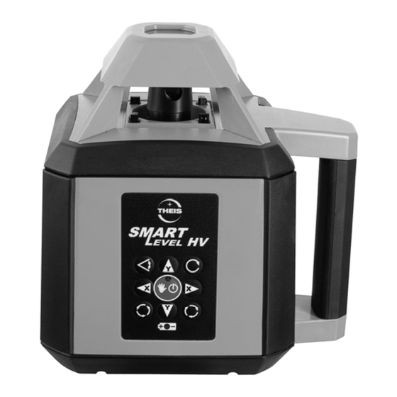
  • Page 32: Eléments De Commande / Info

    1. Eléments de commande / Info Sortie du rayon laser: Plumb Rotation Inclinaison d‘axe y (+) Vitesse de la Scan rotation Indicateur Marche/Arrêt, d’horizontalité, Manuel Manuel Inclinaison (-) Inclinaison (+) d‘axe x d‘axe x Rotation à droite, Rotation à gauche, régime pas-à-pas régime pas-à-pas Inclinaison (-)
  • Page 33: Fonctionnement Horizontal

    à tourner et l’indicateur d’horizontalité s’éteint. 3. Fonctionnement vertical Monté le SMART LEVEL HV sur un trèpied avec le derrière en bas, si bien que le clavier démontre en haut. Cf. point 2 pour de plus amples informations.
  • Page 34: Fonction Tilt

    laser est accélérée si les touches sont enfon- cées plus. Si la butée finale est dépassée pen- dant l’alignement du rayon laser, le rayon laser et l’indicateur de niveau elignotent rapidement. Les butées finales peuvent à nouveau être déverrouillées au moyen des touches fléchées. 4.
  • Page 35: Inclination En Mode De Fonctionnement Manuel

    6. Fonction SCAN En mode Scan, une ligne laser peut être générée dans jusqu'à 4 tailles différentes. Le mode "Scan" peut être activé en appuyant sur la touche "Scan". L'appareil commence à scan- ner au niveau le plus bas. Appuyer à nouveau sur la touche "Scan"...
  • Page 36: Télécommande (Ir)

    Naturellement, des inclinaisons peuvent égale- ment être réglées en mode "Vertical". En mode "Manuel", la mise à niveau automatique du laser est désactivée!!!! 8. Télécommande (IR) La télécommande dispose d'un champ de commande similaire à celui du laser. L'alimentation en courant se fait au moyen de deux piles Micro AAA.
  • Page 37 Si ce n’est pas le cas, l’appareil s’arrête automatiquement après un court instant. Seul le chargeur standard THEIS peut être utilisé pour recharger l’accu au moyen de la prise de char- gement du compartiment de l’accu du niveau laser.
  • Page 38: Récepteur

    10. Récepteur Allumer le récepteur en appuyant sur la touche Marche/Arrêt et sélectionner la fonction souhaitée: Réglage fin ou grossier (le réglage de base du TE 6 est «grossier») et signal acoustique. La fonction choisie apparaît dans l’affichage LCD. Pendant la mesure, cet affichage indique également le sens dans lequel le récepteur doit être déplacé...
  • Page 39 TE 6 Affichage Fin Grossier Flèche pour le sens du mouvement Barre centrale Flèche pour le sens du mouvement Indicateur de batterie Indicateur du signal acoustique Fenêtre de la sonde Affichage LCD (aussi l'arrière) Centre de l‘encoche (droite et à gauche) Appuyer Marche/Arrêt Appuyer signal acoustique...
  • Page 40: Vérification De L'ajustage

    (3 mm max.), cela signifie que l'ajustage est correct. Si les divergences sont plus importantes, l'appareil doit être confié à une entreprise habilité par Theis qui le contrôlera et procèdera à son calibrage. 12. Déclaration du fournisseur / consignes de sécurité...
  • Page 41: Garantie

    Il en va de même pour toute demande de dommages et intérêts, et plus particuliè- rement pour les dommages indirects. Toute interven- tion technique de tiers – c'est-à-dire de toute per- sonne extérieure à la société THEIS – entraîne en outre l'extinction de la garantie.
  • Page 42: Elimination

    À la disposition de la réglementation natio- nale, d'élimination spécifiques à chaque pays doivent être respectées. Informations pour se rendre à Theis. (WEEE - Reg.-Nr. DE 10598800) Batteries / Accus: Ne pas jeter les batteries et accus dans les ordures ménagères, au feu ou à...
  • Page 43: Caractéristiques Techniques

    16. Caractéristiques techniques Laser Laser classe Longueur d‘onde 635nm Puissance de sortie < 1mW Porteé 250 m Plage de nivellement ± 5° Précision ± 1mm/10m Inclination manuel x,y ± 10% Vitesse 0 - 600 U/min Mode Scan 4 - niveaux Autonomie ≈...
  • Page 44 Max. Ausgangsleistung 1 mW Wellenlänge 635 nm Max. Output 1 mW Wavelength 635 nm Änderungen vorbehalten Subject to changes Sous réserve de modifications THEIS FEINWERKTECHNIK GMBH 35236 Breidenbach-Wolzhausen·Germany...

Table des Matières