Publicité

Les langues disponibles

Les langues disponibles

Liens rapides

Bedienungsanleitung
Instructions for use
Mode d'emploi
PCU LED
Pioneering Technology
Lichtpolymerisationsgerät für den
CAD / CAM 3D Druck-Prozess
Light polymerization device for the
CAD / CAM 3D printing process
Photopolymérisateur pour le processus
d'impression CAO / FAO en 3D
Dreve Firmengruppe · Max-Planck-Straße 31 · 59423 Unna/Germany

Publicité

Table des Matières

Dépannage

loading

Sommaire des Matières pour Dreve PCU LED

  • Page 1 PCU LED Pioneering Technology Lichtpolymerisationsgerät für den CAD / CAM 3D Druck-Prozess Light polymerization device for the CAD / CAM 3D printing process Photopolymérisateur pour le processus d’impression CAO / FAO en 3D Dreve Firmengruppe · Max-Planck-Straße 31 · 59423 Unna/Germany...
  • Page 2: Table Des Matières

    Contents Inhalt 1. Description de l’appareil page 44 1. Gerätebeschreibung Seite 4 2. Caractéristiques 2. Technische Daten Seite 5 techniques page 45 3. Konformitätserklärung Seite 6 3. Déclaration de 4. Sicherheitshinweise Seite 7 conformité CE page 46 5. Inbetriebnahme Seite 9 4.
  • Page 3: Gerätebeschreibung

    PCU LED 1. Gerätebeschreibung Die PCU LED (Post Curing Unit LED) ist b) Elektronische Steuerung der Ebene 1 kann nur ein vordefinierter gehärtet werden. Die einzustellende ein Lichtpolymerisationsgerät für das (Mikrocontroller) Prozess ausgewählt werden. In der Ebene Umgebung ist von der Anwendung ab- Aushärten von Bauteilen, die mittels...
  • Page 4: Konformitätserklärung

    Geräte mit einem mit uns abgestimmten Änderung des Gerätes verliert diese Erklärung ihre Gültigkeit. Bemessungsstrom <=16 A je Leiter, Bezeichnung des Gerätes: PCU LED / PCU LED N die keiner Sonderanschlussbedingung 4316 / 4317 unterliegen (IEC 61000-3-3:2013); Gerätetyp: Lichtpolymerisationsgerät...
  • Page 5: Inbetriebnahme

    PCU LED das etwa 9,5 kg schwere Betriebsgewicht Sie sicher, dass die Gasdruckflasche nicht 25. Die vorgeschriebene Betriebs- zuhalten. Beim Arbeiten mit der PCU LED und Wartungsbedingungen dieser sind die allgemeinen Unfallverhütungs- ausreichend stabil und belastbar ist. umkippen kann. Gebrauchsanleitung sind zwingend ein- vorschriften zu beachten.
  • Page 6: Funktionselemente

    PCU LED 7. Funktionselemente 8.1. Bedienung: Starten des Gerätes Vorderansicht Die Software der PCU LED ist unterteilt (1) Durch Einschalten des Netzschalters in zwei Ebenen: Die erste Ebene ist die an der Rückseite des Gerätes gelangen Anwenderebene, in der der Bediener Sie direkt in die Anwenderebene.
  • Page 7 PCU LED 8.3. Bedienung: Anwenderebene Startbildschirm Statusfenster nach Einschalten Durch nochmaliges Bestätigen des Gerätes wird der Belichtungsprozess gestartet. 1 – Programmname 2 – Returntaste 3 – Belichtungsdauer 4 – Druck (mbar) 5 – Belichtungsicon (ON/OFF) 6 – Belichtungsatmosphäre (Luft/Vakuum/Stickstoff) Welcome-Bildschirm Belüften des...
  • Page 8 PCU LED 8.4. Bedienung: Prozessebene Zugang zum Einstellen der Konfigurationslevel Prozessparameter Durch Einschalten des Netzschal- 1 – Returntaste ters an der Rückseite des Gerätes 2 – Programmname (frei definierbar und gleichzeitiges Drücken des durch Drehen des Drehknopfes) Bedienknopfes gelangen Sie in die 3 –...
  • Page 9: Wartung

    PCU LED 9. Pflege und Wartung Zeiteinstellung Vom Anwender durchzuführende Wartungsarbeiten Einstellen des Datums und der Zeit für den Zeitstempel der Pro- Wartungseinheit Wartungshäufigkeit zessaufzeichnung, die u. a. im Glasscheiben im Boden und im Deckel der Polymerisations- täglich * „Finalen Screen“ im Anwender-...
  • Page 10: Monitoring

    PCU LED 10. Monitoring Die verschiedenen Prozessparameter werden durch die in der PCU LED verbaute Sensorik Code Störung Ursache Fehlerbehebung erfasst. Im finalen Screen in der Anwenderebene werden diese angezeigt. Pumpe kann kein Deckeldichtung der Erneuern der Vakuum ziehen. Belichtungskammer Deckeldichtung Erklärung der Parameterdarstellung im finalen Screen in der Anwenderebene...
  • Page 11: Explosionszeichnung

    521022 3 PCU LED Netzteil SNT medical 521023 Posnr. Beschreibung 51090CR2032 Knopfzelle CR 2032 3V 4 Glasscheibe PCU LED 154 x 164 mm 4 mm dick 501024 521022 PCU LED Ansteuerung 5 Spiegelblech Rückseite Unterteil 521025 521023 PCU LED Netzteil SNT medical 6 Spiegelblech Rückseite Deckel...
  • Page 12: Allgemeine Hinweise

    Reparatur- und Instandsetzungsarbeiten · das Gerät in Übereinstimmung mit Die Herstellergarantie beträgt 2 Jahre ab mene Änderungen oder Instandset- an der PCU LED dürfen nur von Fachkräf- dieser Bedienungsanleitung verwen- Lieferdatum. Das Gewährleistungsrecht zungs- und Wartungsarbeiten sowie im ten ausgeführt werden. Die Stromzufuhr det wird.
  • Page 13: Device Description

    PCU LED 1. Device description The PCU LED (Post Curing Unit LED) the control and reading of the current, cured under different environments. The g) Open system is a light polymerization device for the pressure and temperature sensors. environment to be set depends on the...
  • Page 14: Declaration Of Conformity

    (IEC 61000-3- or modification of the machine, not authorised by us, this declaration becomes invalid. 3:2013); German version EN 61000-3-3:2013 Denomination of the machine: PCU LED / PCU LED N EN 61326-1:2013 Electromagnetic compatibility (EMC) – Part 4316 / 4317 3-3: Limits –...
  • Page 15: Commissioning

    22. To avoid the risk of getting caught, tion regulations when handling nitrogen. only touch the lid at the handle. 6. Information on the use of the protective gas (PCU LED (N 12. Only use approved gas pressure 23. Do not operate the device if the bottles.
  • Page 16: Functional Elements

    7. Functional elements 8.1. Operation: Starting the device Overview The software of the PCU LED is subdivi- (1) Switching on the power plug at the ded into two levels: The first level is the back of the device brings you directly user level, where the operator can select to the user level.
  • Page 17 PCU LED 8.3. Operation: User level Start screen after Status window switching on the device Additional confirmation starts the exposure process. 1 – Programme name 2 – Return button 3 – Exposure time 4 – Pressure (mbar) 5 – Exposure icon (ON/OFF) 6 –...
  • Page 18 PCU LED 8.4. Operation: Process level Access to the Setting the process configuration level parameters Switching on the power switch 1 – Return button at the rear of the device and 2 – Programme name simultaneously pressing the (freely definable by turning...
  • Page 19: Maintenance

    PCU LED 9. Maintenance Time setting Maintenance work to be performed by the user Setting the date and time for the time stamp of the process Maintenance unit Maintenance frequency recording which is shown, inter Clean the glass panes in the bottom and the lid of the * daily alia, in the “final screen”...
  • Page 20: Monitoring

    The different process parameters are recorded by means of the sensors used in the Code Defect Cause Troubleshooting PCU LED. These are shown in the final screen in the user level. Pump cannot draw Cover gasket for Replacement any vacuum...
  • Page 21: Exploded View

    5 mirror plate, rear side lower part 521025 521023 PCU LED Netzteil SNT medical 6 mirror plate, rear side cover 521026 501024 Glasscheibe PCU LED 154 x 164mm 4mm dick 521025 Spiegelblech Rückseite Unterteil 7 mirror plate, sideways right 521027 521026 Spiegelblech Rückseite Deckel ohne Abbildung, ähnlich Pos.
  • Page 22: General Information

    · the device is used in accordance with The manufacturer warranty is 2 years repair and maintenance work which PCU LED may only be performed by spe- these operating instructions. from date of delivery. The warranty have been incorrectly completed by the cialists.
  • Page 23: Description De L'appareil

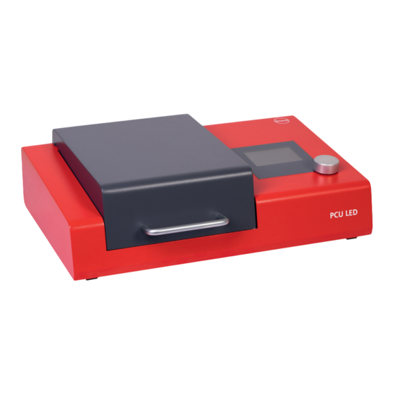
    PCU LED 1. Description de l’appareil La PCU LED (Post Curing Unit LED) est b) Commande électronique (micro- accessible aux utilisateurs et proprié- à régler dépend de l’application et un photopolymérisateur pour durcir contrôleur) taires des processus. Le niveau 2 n’est figure dans le tableau 1.
  • Page 24: Déclaration De Conformité Ce

    Désignation de l’appareil : PCU LED / PCU LED N un courant assigné <=16 A par phase 4316 / 4317 et non soumis à un raccordement condi- Type d’appareil :...
  • Page 25: Mise En Service

    PCU LED. et ca-pable de supporter un poids d’env. 14. Ne reliez jamais la bouteille de gaz 9,5 kg.
  • Page 26: Éléments Fonctionnels

    7. Éléments fonctionnels 8.1. Commande : lancement de l’appareil Vue de face Le logiciel de la PCU LED est divisé en reil. (1) En allumant l’interrupteur réseau deux niveau : le premier niveau est le au dos de l’appareil, vous accédez direc- niveau de l’utilisateur, où...
  • Page 27 PCU LED 8.3. Commande : niveau de l’utilisateur Écran de démarrage Fenêtre d’état après l’allumage Le processus d’exposition est de l’appareil lancé par une confirmation réitérée. 1 – Nom du programme 2 – Touche « Retour » 3 – Durée d’exposition 4 –...
  • Page 28 PCU LED 8.4. Commande : niveau des processus Accès au niveau des Réglage des paramètres configurations de processus Vous accédez au niveau des pro- 1 – Touche « Retour » cessus en allumant l’interrupteur 2 – Nom du programme (définissable réseau situé...
  • Page 29: Entretien

    PCU LED 9. Entretien et maintenance Réglage de l’heure Travaux de maintenance à effectuer par l’utilisateur Réglage de la date et de l’heure pour l’estampille temporelle de Unité de maintenance Fréquence de main- l’enregistrement des processus tenance affiché entre autres dans l’...
  • Page 30: Suivi

    Les différents paramètres de processus sont mesurés par les capteurs intégrés dans la La pompe ne peut Joint d’étanchéité Renouveler le PCU LED. Ils sont affichés sur l’écran final dans le niveau d’utilisateur. pas tirer le vide. Arrêt du couvercle de la joint d’étanchéité...
  • Page 31: Liste De Pièces De Rechange

    521022 3 Bloc d’alimentation SNT medical PCU LED 521023 Posnr. Beschreibung 51090CR2032 Knopfzelle CR 2032 3V 4 Vitre PCU LED 154 x 164 mm 4 mm d’épaisseur 501024 521022 PCU LED Ansteuerung 5 Tôle réfléchissante partie arrière inférieure 521025 521023 PCU LED Netzteil SNT medical 6 Tôle réfléchissante partie arrière couvercle...
  • Page 32: Informations Générales

    Les prestations de garantie formé de la société Dreve. En cas de répa- · l’appareil est utilisé uniquement par du fications techniques. ne portent pas sur l’usure naturelle, ni sur ration, veuillez vous adresser à...
  • Page 33 Dreve Firmengruppe · Max-Planck-Straße 31 · 59423 Unna/Germany Tel +49 2303 8807-0 · Fax: +49 2303 82909 · info@dreve.de · www.dreve.com...

Table des Matières