Zehnder ComfoAir 70 Instructions De Montage
Masquer les pouces
Voir aussi pour ComfoAir 70:
- Mode d'emploi et notice de montage (47 pages) ,
- Instructions de montage (29 pages) ,
- Mode d'emploi (6 pages)
Table des Matières
Publicité
Les langues disponibles
Les langues disponibles
Liens rapides
Decorative radiators
Comfortable indoor ventilation
ComfoAir 70 / ComfoSpot 50
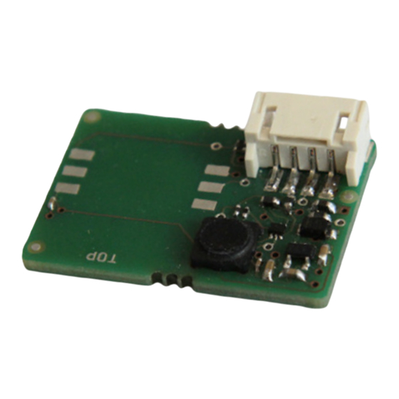
Sensorik - Sensor system - Capteurs - Sensori -
Sensorsysteem - Czujniki
Montagehinweise - Installation notes - Instructions de montage - Indicazioni per
il montaggio - Montageaanwijzingen - Wskazówki dotyczące montażu
Heating and cooling ceiling systems
Clean air solutions
Publicité
Table des Matières

Manuels Connexes pour Zehnder ComfoAir 70


Sommaire des Matières pour Zehnder ComfoAir 70
- Page 1 Decorative radiators Comfortable indoor ventilation Heating and cooling ceiling systems Clean air solutions ComfoAir 70 / ComfoSpot 50 Sensorik - Sensor system - Capteurs - Sensori - Sensorsysteem - Czujniki Montagehinweise - Installation notes - Instructions de montage - Indicazioni per...
- Page 2 Alle Rechte vorbehalten. Die Zusammenstellung dieser Bedienungsanleitung erfolgte mit größter Sorgfalt. Dennoch haftet der Herausgeber nicht für Schäden aufgrund von fehlenden oder nicht korrekten Angaben in dieser Bedienungsanleitung. Bei Meinungsverschiedenheiten ist der deutsche Originaltext letztendlich verbindlich. All rights reserved. This manual has been compiled with the utmost care. However, the publisher cannot be held liable for any damage caused as a result of missing or incorrect information in this manual.
-
Page 12: Utilisation Prévue
SENSOR X8 Trois modules de capteurs sont marron disponibles pour le fonctionnement entièrement automatique des blanc appareils de ventilation ComfoAir 70 vert et ComfoSpot 50 : jaune HUMIDITE (capteur combiné Tab. 1 : Code couleur de température et d’humidité) COV (capteur de COV et capteur combiné... - Page 13 Capteurs ComfoSpot 50 Retirer la coiffe supérieure du capot intérieur et enlever les fer- metures de filtre et les filtres. Retirer le couvercle en PVC de la Retirer le bouchon à passage de platine de commande et ôter avec câble dans la zone de la platine de précaution le câble en nappe du commande du boîtier en EPP.
- Page 14 Capteurs ComfoAir 70 câble aboutisse dans la zone de la platine de commande. Tirer sur le capot de recouvrement design supérieur pour le retirer et dévisser le capot de recouvrement design inférieur. Retirer la partie supérieure du boîtier en EPP et guider le câble des capteurs avec les extrémités...
-
Page 15: Caractéristiques De Régulation
Capteurs Caractéristiques de régulation Lors de l’utilisation de la fonction La fonction bain active la vitesse automatique, les ventilateurs de de rotation maximale des ven- l’appareil sont régulés en fonction tilateurs à partir d’une humidité de la concentration de la grandeur relative de l’air de 80 %.