Zehnder ComfoAir 70 Instructions De Montage
Masquer les pouces
Voir aussi pour ComfoAir 70:
- Mode d'emploi et notice de montage (47 pages) ,
- Instructions de montage (28 pages) ,
- Mode d'emploi (6 pages)
Publicité
Les langues disponibles
Les langues disponibles
Liens rapides
Decorative radiators
Comfortable indoor ventilation
ComfoAir 70 / ComfoSpot 50
ComfoLED / ComfoLED CH
Montagehinweise - Installation notes - Instructions de montage - Indicazioni per
il montaggio - Montageaanwijzingen - Wskazówki dotyczące montażu
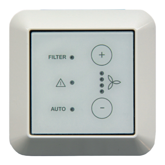
ComfoLED
Heating and cooling ceiling systems
ComfoLED CH
Clean air solutions
Publicité

Manuels Connexes pour Zehnder ComfoAir 70

Sommaire des Matières pour Zehnder ComfoAir 70
- Page 1 Decorative radiators Comfortable indoor ventilation Heating and cooling ceiling systems Clean air solutions ComfoAir 70 / ComfoSpot 50 ComfoLED / ComfoLED CH Montagehinweise - Installation notes - Instructions de montage - Indicazioni per il montaggio - Montageaanwijzingen - Wskazówki dotyczące montażu...
- Page 2 Alle Rechte vorbehalten. Die Zusammenstellung dieser Bedienungsanleitung erfolgte mit größter Sorgfalt. Dennoch haftet der Herausgeber nicht für Schäden aufgrund von fehlenden oder nicht korrekten An- gaben in dieser Bedienungsanleitung. Bei Meinungsverschiedenheiten ist der deutsche Ori- ginaltext letztendlich verbindlich. All rights reserved. This manual has been compiled with the utmost care.
- Page 3 Montageanleitung ................Installation notes ................8-11 Instructions de montage ..............12-15 Indicazioni per il montaggio ............... 16-19 Montageaanwijzingen ............... 20-23 Wskazówki dotyczące montażu ............24-27...
- Page 4 externe Bedieneinheit Verwendungszweck Aufbau / Lieferumfang Die Comfo LED (ComfoLED CH) bietet die Möglichkeit das Lüftungs- gerät bequem aus der Ferne zu bedienen. Das Bedienteil ist aus- schließlich für eine Unterputzin- stallation im Innenbereich in die marktüblichen Schalterprogramme geeignet und wird über ein maxi- ComfoLED mal 25 m langes, 4-adriges Kabel (z.B.
- Page 5 externe Bedieneinheit Funktionalität Elektrischer Anschluss Lüftungsgeräteseitig: Die Bedieneinheit verfügt über be- rührungssensitive Schaltflächen, Die Buchse der Mikrosteckverbin- das heißt, durch Berühren der be- dung des Anschlusskabels ist in treffenden Tasten werden die je- den Stecker der Mikrosteckverbin- weiligen Bedienfunktionen aus- dung BUS X7 der Steuerungspla- gelöst.
- Page 6 externe Bedieneinheit ComfoSpot 50 Farb- Aderbelegung Farb- codie- Federzugklem- codie- rung rung Ziehen Sie das Steckverbindungs- Kabel Steck- schluss- bau- teil mit den Schraubklemmen ab und verbin- dien- kabel seits klemmen Sie die Adern des bausei- einheit tigen Kabels an. Notieren Sie die Rot (RT) Farbcodierung! Orange...
- Page 7 Sie die beiden Teile des Steckver- binders zusammen und verbringen Sie die Steckverbindung im Bereich der Kabeleinführung. ComfoAir 70 Stecken Sie nach Einschieben des Gerätes in das Wandeinbaurohr die Ziehen Sie das Steckverbindungs- beiden Teile des Steckverbinders teil mit den Schraubklemmen ab...
- Page 8 External control panel Intended purpose Design / Scope of delivery The Comfo LED (ComfoLED CH) allows the ventilation unit to be conveniently operated remote- ly. The control panel is only suit- able for indoor in-wall installation in conventional switch ranges and connected ventila- tion unit with a 4-core cable with...
- Page 9 External control panel Functionality Electrical connection Ventilation unit side: The control panel has touch-sensi- tive buttons, which means the re- The socket of the connection ca- spective operating functions are ble’s micro connection must be in- triggered by touching the relevant serted into the plug of the BUS X7 buttons.
- Page 10 External control panel ComfoSpot 50 Colour Wire assign- Colour coding of ment spring- coding the con- type terminals of the Disconnect the plug-in connector nection on-site Plug-in Con- cable cable part with the screw-type terminals connec- trol and connect the wires of the on- unit site cable.
- Page 11 Plug both parts of the plug-in connector together and pass the plug connection into the cable entry area. ComfoAir 70 After sliding the unit into the wall Disconnect the plug-in connector mounting pipe, plug the two parts part with the screw-type terminals...
- Page 12 Interface de commande externe Utilisation prévue Structure / contenu de la livraison Le Comfo LED (ComfoLED CH) permet une commande aisée de l’appareil de ventilation à distance. L’interface de commande est exclu- sivement conçue pour une installa- tion encastrée en intérieur, dans les gammes d’interrupteurs courantes sur le marché.
- Page 13 Interface de commande externe Fonctionnalité Raccordement électrique Côté appareil de ventilation : L’interface de commande dispose de surfaces tactiles, si bien qu’il suffit Le connecteur femelle du micro- d’effleurer les touches correspon- connecteur du câble de raccorde- dantes pour activer les fonctions ment doit être branché...
- Page 14 Interface de commande externe ComfoSpot 50 Code Affectation des Code couleur conducteurs couleur Retirer la partie du connecteur câble de câble Con- Inter- raccor- fourni avec les bornes à vis et brancher necteur face dement par le les conducteurs du câble fourni par client com- le client.
- Page 15 ComfoAir 70 Après avoir inséré l’appareil dans Retirer la partie du connecteur le tube de montage mural, emboî- avec les bornes à vis et brancher ter les deux parties du connecteur les conducteurs du câble fourni par...
- Page 16 Unità di comando esterna Impiego previsto Struttura / dotazione Comfo LED (ComfoLED CH) ester- na offre la possibilità di controllare comodamente a distanza il dispo- sitivo di ventilazione. Il pannello di comando è idoneo esclusivamen- te all’installazione incassata all’in- terno di gamme di interruttori comu- ni e viene collegato al dispositivo di ComfoLED ventilazione per mezzo di un cavo a...
- Page 17 Unità di comando esterna Funzionalità Collegamento elettrico Lato del dispositivo di ventilazione: L’unità di comando presenta super- fici di contatto sensibili al tatto, vale La presa del microconnettore del ca- a dire che toccando determinati pul- vo di collegamento deve essere in- serita nella spina del microconnetto- santi si attivano le rispettive funzioni di comando.
- Page 18 Unità di comando esterna ComfoSpot 50 Codifica Assegnazione Codifi- dei colo- del filo ca dei Estrarre la parte del connettore con ri del cavo colori Con- Unità di collega- del ca- i morsetti a vite e fissare i fili del ca- net- di co- mento...
- Page 19 Uni- re i due pezzi del connettore e por- tare il connettore nel punto di intro- duzione del cavo. ComfoAir 70 Dopo aver inserito l’apparecchio nel tubo di montaggio a parete, col- Estrarre la parte del connettore...
- Page 20 externe bedieningsunit Gebruiksdoel Opbouw / leveringsomvang Met de Comfo LED (ComfoLED CH) kan de ventilatie-unit comfor- tabel op afstand worden bediend. De bedieningsunit is uitsluitend geschikt voor inbouwinstallatie in binnentoepassingen in gangbare schakelaarprogramma's en wordt via een maximaal 25 m lange ka- ComfoLED bel met 4 aders (bijv.
- Page 21 externe bedieningsunit Functionaliteit Elektrische aansluiting Ventilatie-unitzijde: De bedieningsunit beschikt over aanrakingsgevoelige schermknop- De bus van de microconnector van pen, wat inhoudt dat de diver- de aansluitkabel moet in de stek- se bedieningsfuncties door aanra- ker van de microconnector BUS X7 king van de bijbehorende knoppen van de besturingsprintplaat van de in gang worden gezet.
- Page 22 externe bedieningsunit ComfoSpot 50 Kleurco- Draadtoewijzing Kleurco- dering dering van de kabel ter Con- Bestu- Trek het insteekverbindingsdeel aansluit- plaatse nec- ring- kabel met de schroefklemmen af en sluit seen- heid de aders van de ter plekke te leve- ren kabel aan. Noteer de kleurco- Rood dering! Oranje...
- Page 23 Nadat het apparaat in de mantel- ComfoAir 70 buis is geschoven, steekt u de twee delen van de connector in elkaar en Trek het insteekverbindingsdeel plaatst u de connector in de vrije met de schroefklemmen af en sluit ruimte vóór de besturingsprintplaat.
- Page 24 Zewnętrzny panel sterowania Przeznaczenie Budowa / zakres dostawy Comfo (ComfoLED umożliwia wygodną i zdalną ob- sługę centrali wentylacyjnej. Pa- nel sterowania jest przeznaczo- ny wyłącznie do instalacji pod- tynkowych, przeznaczonych dla dostępnych na rynku modułów przełączników i montowanych we ComfoLED wnętrzach, oraz jest połączony z centralą...
- Page 25 Zewnętrzny panel sterowania Działanie Zasilanie elektryczne Po stronie centrali wentylacyjnej: Panel sterowania posiada dotyko- we przyciski, co oznacza, że do- Gniazdo mikrozłącza kabla przyłą- tknięcie dowolnego przycisku po- czeniowego należy podłączyć do woduje aktywację odpowiedniej wtyczki mikrozłącza BUS X7 płytki funkcji obsługowej.
- Page 26 Zewnętrzny panel sterowania ComfoSpot 50 Oznaczenia Przyporządko- Oznacze- kolorystycz- wanie żył nia kolo- ne kabla rystycz- przyłącze- ne kabla Odłączyć element złącza wtykowe- Złącze Panel niowego zapew- wtyko- stero- nianego go z zaciskami śrubowymi i podłą- wania przez in- czyć żyły kabla w miejscu montażu. westora Zapisać...
- Page 27 BUS X7 płyt- cze wtykowe w obszarze prowad- ki sterującej. nicy kablowej. ComfoAir 70 Odłączyć element złącza wtykowe- go z zaciskami śrubowymi i podłą- Po wsunięciu urządzenia w otwo- czyć żyły kabla w miejscu montażu.
- Page 28 Great Britain Italy Poland Zehnder Comfosystems UK Ltd Zehnder Tecnosystems S.r.l. Zehnder Polska Sp. z o.o. Unit 1, Brookside Avenue Via XXV Luglio, 6 ul. Kurpiów 14a Rustington West Sussex Campogalliano (MO) 41011 52-214 Wrocław BN16 3LF...