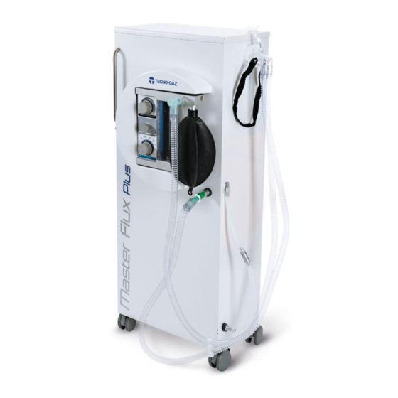
Tecno-gaz Master Flux Plus Mode D'emploi
Masquer les pouces Voir aussi pour Master Flux Plus:
Table des Matières

Publicité

Les langues disponibles
  • FR

Les langues disponibles

  • FRANÇAIS, page 69

Liens rapides

Istruzioni per l'uso
Instructions for use
Mode d'emploi
Bedienungsanleitung
Instrucciones de uso
Instruções de uso
LABEL:
ITALIANO
ENGLISH
Translation
FRANCAIS
Traduction
DEUTSCH
Übersetzung
ESPANOL
Traducción
PORTUGUÊS
Tradução
0ZMFI0011 – REV4 – 04/07/2019

Publicité

Table des Matières
loading

Sommaire des Matières pour Tecno-gaz Master Flux Plus

  • Page 1 LABEL: Istruzioni per l’uso ITALIANO Instructions for use ENGLISH Translation Mode d’emploi FRANCAIS Traduction Bedienungsanleitung DEUTSCH Übersetzung Instrucciones de uso ESPANOL Traducción Instruções de uso PORTUGUÊS Tradução 0ZMFI0011 – REV4 – 04/07/2019...
  • Page 2 Questo manuale è idoneo per i seguenti articoli: This manual is suitable for the following items: Ce manuel est adapté pour les éléments suivants: Dieses Handbuch ist geeignet für die folgenden Elemente: Este manual es adecuado para los siguientes elementos: Este manual é...
  • Page 3: Table Des Matières

    COMPONENTI VERSIONE A MURO INTERFACCIA UTENTE MASCHERINE MISURE MASCHERINE CIRCUITO MASCHERINE INSTALLAZIONE INSTALLAZIONE MASTER FLUX PLUS A MOBILE INSTALLAZIONE MASTER FLUX PLUS A PARETE COLLEGAMENTO CIRCUITI E ACCESSORI MASTER FLUX EVACUAZIONE GAS ESALATI 6.4.1 COLLEGAMENTO DIRETTO ALL’ESTERNO DELLO STUDIO 6.4.2 COLLEGAMENTO ALL’ASPIRATORE CHIRURGICO...
  • Page 4 ITALIANO IMPIEGO E DESTINAZIONE D’USO DESTINAZIONE D’USO Il MASTER FLUX PLUS è un dispositivo per la somministrazione di una miscela di O al paziente, utilizzato nelle tecniche di sedazione cosciente /analgesia sedativa. IMPIEGO Nella miscela somministrata i valori di concentrazione sono: ≥...
  • Page 5: Sicurezza

    Il testo è valido per i dispositivi venduti in Italia. TECNO-GAZ consiglia l’applicazione di questo testo per tutti gli utilizzatori del dispositivo, integrandolo con le normative vigenti nel paese di utilizzo.
  • Page 6: Marcatura Di Sicurezza

    ITALIANO L’utilizzo del dispositivo Master Flux Plus va abbinato all'uso del PULSIOSSIMETRO che deve essere routinario in corso di sedazione cosciente. Il significato della lettura dei valori rilevati:  Livelli di saturazione di O Grado di ipossia ≥ 95% Nessuna ipossia...
  • Page 7: Movimentazione

    ITALIANO Movimentazione Per muovere il mobile Master Flux Plus usare esclusivamente le maniglie in dotazione. Figura 1 Non spingere il mobile senza usare le apposite maniglie. non sedersi o appoggaire pesi sopra il mobile. Prima di muovere il mobile riposizionare con cura mascherina e i tubi negli appositi sistem idi fissaggio, evitando inciampi o rotture.
  • Page 8: Dati Tecnici

    IMPOSTANDO: EROGAZIONE 10 Nl/min. MISCELAZIONE 50 % AUTONOMIA: OSSIGENO 400 min PROTOSSIDO DI AZOTO 950 min  In base alle medie di consumo del gas TECNO-GAZ consiglia di sostituire la bombola di Protossido di Azoto ogni 2 bombole di Ossigeno.
  • Page 9 ITALIANO Figura A Figura B...
  • Page 10 ITALIANO DISIMBALLAGGIO NON È CONSENTITO SOVRAPPORRE I MOBILI MASTER FLUX PLUS IMBALLATI L’imballo non deve subire urti, deve essere maneggiato con cura evitando di farlo rotolare o farlo cadere. Non utilizzare apparecchi che presentano danni evidenti dovuti al trasporto. ...
  • Page 11: Componenti

    ITALIANO COMPONENTI Elenco componenti in dotazione...
  • Page 12: Componenti Versione A Mobile

    ITALIANO COMPONENTI versione a mobile Figura 2 FIGURA POSIZIONE Q.TA’ CODICE DESCRIZIONE SMFA144 COPERTURA IN PLASTICA SMFA506 SCATOLA FLUSSOMETRICA SMFA223 DISTANZIATORE CM25021 VITE AD ALETTE M5 3MECQ0010 DISTANZIATORE CM20015 RONDELLA CM25019 DADO AD ALETTE M6 SMFA237 PORTAGOMMA ELIMINAZIONE GAS...
  • Page 13: Componenti Versione A Muro

    ITALIANO COMPONENTI versione a muro Figura 3-4 A MURO (Figura 3-4) FIGURA POSIZIONE Q.TA’ CODICE DESCRIZIONE SMFA313 PERNO SMFA364 TUBO O SMFA365 TUBO N SMFA301 SUPPORTO A PARETE SMFA501 PIASTRA A PARETE CM30011 MANOPOLA FISSAGGIO PERNO...
  • Page 14: Interfaccia Utente

    ITALIANO INTEFACCIA UTENTE Figura 5 Manopola FLOW Pulsante FLUSH Manopola % N Flussimetro N Flussimetro O Pallone reservoir Portagomma per collegamento maschera...
  • Page 15: Mascherine

    ITALIANO MASCHERINE ❷ ❶ ❸ ❹ Figura 6 ❶ Zona di appoggio per la fronte del paziente ❷ Entrata del gas con valvola di non ritorno Uscita del gas con valvola di non ritorno + freccia stampata sul PC per indicare la ❸...
  • Page 16: Circuito Mascherine

    ITALIANO CIRCUITO MASCHERINE Figura 8 CIRCUITO COMPLETO DI MASCHERE Figura 9  Per i ricambi dei componenti singoli, vedere sul manuale d’uso di “Circuiti e maschere”.
  • Page 17: Installazione

    INSTALLAZIONE Togliere l’imballo e controllare lo stato dell’apparecchio. Non utilizzare apparecchi che presentano danni evidenti dovuti al trasporto. INSTALLAZIONE MASTER FLUX PLUS A MOBILE MONTAGGIO SCATOLA FLUSSOMETRICA (Figura 2) vedi Guida rapida allegata 0ZMFI0007 Avvitare i 3 distanziatori in acciaio (3) sulla scatola flussometrica (2).
  • Page 18 ITALIANO Figura 10 FIGURA POSIZIONE Q.TA’ CODICE DESCRIZIONE MF847ZMF RIDUTTORE O (ITA) MF011ZMF RIDUTTORE N O (ITA) VALVOLA MANOMETRO...
  • Page 19: Installazione Master Flux Plus A Parete

    Fissare il SUPPORTO MASTER FLUX PLUS a parete (Pos13) utilizzando n.4 tasselli per parete Ø14 mm M8. Fissare la PIASTRA MASTER FLUX PLUS a parete (Pos14) con n.4 tasselli per parete Ø 8 Avvitare alla base della scatola flussometrica il perno (Pos10).
  • Page 20 ITALIANO NOTE SULL’IMPIANTO CENTRALIZZATO L’installazione deve essere eseguita da tecnici specializzati, l’impianto centralizzato deve essere eseguito in conformità alle direttive vigenti Direttiva Europea 93/42/CE Collegare la presa a parete al punto equipotenziale dell’impianto elettrico, con i connettori a occhiello in dotazione. I riduttori in dotazione devono essere collegati alle bombole dell’impianto centralizzato.
  • Page 21: Collegamento Circuiti E Accessori Master Flux

    ITALIANO COLLEGAMENTO CIRCUITI E ACCESSORI MASTER FLUX PLUS: Figura 13 FIGURA POSIZIONE Q.TA’ CODICE DESCRIZIONE MANOPOLA ‘ FLOW ’ PULSANTE ‘ FLUSH ’ MANOPOLA ‘ % N2O ‘ INDICATORE DI PORTATA N2O INDICATORE DI PORTATA O2 3MEDN0001 PALLONE IN GOMMA...
  • Page 22: Evacuazione Gas Esalati

    Verificare la conformità alle normative vigenti nel paese di utilizzo. 6.4.1 COLLEGAMENTO DIRETTO ALL’ESTERNO DELLO STUDIO MASTER FLUX PLUS A MOBILE Avvitare i portagomma (Figura 2 Pos 8/9) al mobile. Eliminare la valvola in dotazione. Collegare il tubo, scarico gas del circuito maschera, al portagomma (Figura 15).
  • Page 23 ITALIANO Figura 15...
  • Page 24: Collegamento All'aspiratore Chirurgico

    ITALIANO 6.4.2 COLLEGAMENTO ALL’ASPIRATORE CHIRURGICO MASTER FLUX PLUS A MOBILE Avvitare i portagomma (Figura 2 Pos 8/9) al mobile. Collegare il tubo, scarico gas del circuito maschera, al portagomma (Figura 17). Collegare il circuito aspirazione (Figura 16), al portagomma del mobile.
  • Page 25 ITALIANO Figura 17...
  • Page 26: Funzionamento Del Dispositivo

    ITALIANO FUNZIONAMENTO DEL DISPOSITIVO COMANDI E DIPOSITIVI DI INTERFACCIA UTILIZZATORE Figura 18 TASTI COMANDO (FIGURA 10) MANOPOLA FLOW - REGOLAZIONE FLUSSO EROGATO PULSANTE DI EMERGENZA FLUSH - EROGAZIONE SOLO OSSIGENO MANOPOLA REGOLAZIONE % PROTOSSIDO DI AZOTO ELEMENTI DI CONTROLLO FLUSSO OSSIGENO PURO FLUSSO PROTOSSIDO DI AZOTO PURO PALLONE (VERIFICA - FLUSSO IDONEO AL PAZIENTE)
  • Page 27: Istruzioni Di Utilizzo

    ITALIANO ISTRUZIONI DI UTILIZZO Prima di iniziare ad utilizzare il dispositivo MASTER FLUX PLUS nella versione a mobile, bloccare le ruote munite di freno premendo verso il basso le apposite linguette. Nel caso si rendesse necessario spostare l’apparecchio (ad esempio da una stanza ad un’altra) sbloccare le ruote e spingere delicatamente il dispositivo utilizzando le maniglie vedi...
  • Page 28 ITALIANO Somministrare, servendoci della manopola FLOW (Figura 18 Pos A), un flusso di 3 Lt/min di ossigeno per 30 secondi. COMUNICARE AL PAZIENTE DI INSPIRARE ED ESPIRARE CON IL NASO. Utilizzare la manopola FLOW, per regolare il flusso. Variare progressivamente il flusso, valutare lo stato del pallone (Figura 18 Pos F), il pallone deve assumere una forma che noi definiremo di mezzo pieno mezzo vuoto.
  • Page 29 ITALIANO LA MISCELA DI GAS SOMMINISTRATA AL PAZIENTE: NON DEVE ESSERE SUPERIORE AL 70% DI PROTOSSIDO DI AZOTO NON DEVE ESSERE INFERIORE AL 30% DI OSSIGENO Se il paziente accusa sintomi di malessere (nausea, vertigini, mal di testa), interrompere IMMEDIATAMENTE la terapia. Sul dispositivo è...
  • Page 30: Rianimazione Con Il Master Flux Plus

    (ruotare in senso orario il rubinetto). Togliere il kit maschera dal MASTER FLUX PLUS sfilandolo dal tubo spiralato. Inserire nel tubo spiralato nell’apposito raccordo (30). Togliere la sacca (F) e inserire l’apposito tappo (T).
  • Page 31 ITALIANO FLOW Figura 19 FIGURA POSIZIONE Q.TA’ CODICE DESCRIZIONE TUBO SPIRALATO - CM88051 RACCORDO – SMFA278 1504/A TUBO OSSIGENO – CM84022 OPZIONALE PALLONE RIANIMAZIONE – 1025-2 MASCHERA RIANIMAZIONE – CM84014...
  • Page 32: Manutenzione

    Prima e dopo l’utilizzo pulire, detergere o sterilizzare i particolari a contatto con il paziente o con il suo respiro.  Pulire con Detergente con effetto antistatico il Plaxiglass® di protezione dei flussimetri Tabella per la pulizia dei componenti MASTER FLUX PLUS STERILIZZAZIONE A N°CICLI FIG/POS MATERIALE...
  • Page 33: Manutenzione Programmata

    MANUTENZIONE PROGRAMMATA  Prima di ogni utilizzo controllare l’integrità dei componenti Nel caso il MASTER FLUX PLUS rimanga fermo per più di un mese, eseguire un controllo funzionamento. Il dispositivo MASTER FLUX PLUS è munito di sicurezze che regolamentano il corretto controllo del dispositivo, tuttavia si consiglia di verificare periodicamente il funzionamento del dispositivo eseguendo i seguenti controlli ordinari.
  • Page 34: Segnalazioni

    Riduttore di pressione non Sostituire il riduttore Non eroga ossigeno funzionante Problemi interni alla scatola Controllo del dispositivo presso flussometrica TECNO-GAZ Mancanza di ossigeno Caricare la bombola Non eroga protossido di azoto Riduttore di pressione non Sostituire il riduttore funzionante Azzerare la manopola ‘FLOW’...
  • Page 35: Procedure Per Servizio Ed Assistenza

    ITALIANO PROCEDURE PER SERVIZIO ED ASSISTENZA L’assistenza tecnica deve essere richiesta al deposito che ha fatturato il dispositivo, oppure direttamente a: TECNO–GAZ S.p.A. Strada Cavalli 4, 43038, Sala Baganza, Parma, ITALIA. www.tecnogaz.com PHONE +39 0521 8380 +39 0521 833391 Service1@tecnogaz.com Sarà...
  • Page 36 WALL-MOUNTED COMPONENTS USER INTERFACE MASKS MASKS MEASURES MASKS CIRCUIT INSTALLATION INSTALLATION OF UNIT-MOUNTED MASTER FLUX PLUS INSTALLATION OF WALL-MOUNTED MASTER FLUX PLUS CONNECTING CIRCUITS AND ACCESSORIES EVACUATION OF EXHALED GASES 6.4.1 DIRECT CONNECTION TO THE OUTSIDE OF THE OFFICE 6.4.2...
  • Page 37: Utilisation And Intended Use

    ENGLISH UTILISATION AND INTENDED USE INTENDED USE MASTER FLUX PLUS is a device designed for conscious sedation or sedative analgesia. Conscious sedation consists in administering a mixture of nitrous oxide and oxygen to the patient. The concentrations of the administered mixture are: ≥...
  • Page 38: Safety

    ENGLISH SAFETY Use of the PULSE OXIMETER must be routine during conscious sedation. The meaning of the detected values: Saturation values O2 Hypoxia level ≥ 95% No hypoxia 90-94% Low-grade hypoxia 85-89% Moderate hypoxia 84% Serious hypoxia Safety marking The device complies with Directive 93/42 EEC as amended. The conformity declaration is provided in attachment to the device.
  • Page 39: Handling

    ENGLISH Handling Please only use the supplied handles to move the Master Flux Plus furniture unit. Figure 1 Do not push the furniture unit without using ghe appropriate handles. Do not sit on the furniture item or place any weights on it.
  • Page 40: Technical Data

    AVAILABLE VOLUME 4600 gaseous Litres BY SETTING: DELIVERY 10 NLt/min MIXTURE 50 % AUTONOMY: OXYGEN 400 min NITROUS OXIDE 950 min  Taking into account the average gas consumption parameters, TECNO-GAZ advises replacing a nitrous oxide tank every 2 oxygen tanks.
  • Page 41 ENGLISH Figure A Figure B...
  • Page 42: Unpacking

    ENGLISH UNPACKING IT IS FORBIDDEN TO STACK MASTER FLUX PLUS UNITS The packing shall not undergo any shock and shall be handled with care avoiding letting it roll or fall. Do not use appliances with clear damages due to the transport.
  • Page 43: Components

    ENGLISH DESCRIPTION OF COMPONENTS Components supplied list...
  • Page 44: Unit-Mounted Components

    ENGLISH Unit-mounted COMPONENTS Figure 2 FIGURE POSITION Q.TY CODE DESCRIPTION SMFA144 PLASTIC COVERING SMFA506 FLOW MEASUREMENT BOX SMFA223 SPACER CM25021 M5 FLAP SCREW 3MECQ0010 SPACER CM20015 WASHER CM25019 M6 FLAP NUT SMFA237 GAS ELIMINATION HOSE FITTING...
  • Page 45: Wall-Mounted Components

    ENGLISH Wall-mounted COMPONENTS Figure 3-4 WALL MOUNTED (Figures 3-4) FIGURE POSITION Q.TY CODE DESCRIPTION SMFA313 SMFA364 TUBE SMFA365 O TUBE SMFA301 WALL-MOUNTED SUPPORT SMFA501 WALL PLATE CM30011 PIN SECURING KNOB...
  • Page 46: User Interface

    ENGLISH USER INTERFACE Figure 5 FLOW knob FLUSH button O knob O flowmeter flowmeter Rubber bag Mask connection nozzle...
  • Page 47: Masks

    ENGLISH MASKS ❷ ❶ ❸ ❹ Figure 6 ❶ Support area for the patient's forehead ❷ Gas inlet with non-return valve ❸ Gas outlet with non-return valve and PC printed arrow to indicate the flow direction ❹ Velcro elastic band with plastic hooks MASKS MEASURES MF835ZMF MF836ZMF...
  • Page 48: Masks Circuit

    ENGLISH MASKS CIRCUIT Figure 8 COMPLETE CIRCUIT OF MASKS Figure 9  For parts of individual components, refer to the "Circuits and Masks" user manual.
  • Page 49: Installation

    INSTALLATION Remove the packaging and check the conditions of the equipment. Do not use equipment that presents evident damage due to transportation. Installation of unit-mounted MASTER FLUX PLUS FLOWMETER BOX INSTALLATION (Figure 2) see enclosed Quick Guide 0ZMFI0007 Screw the 3 steel spacers (3) onto the flowmeter box (2).
  • Page 50 ENGLISH Figura 10 FIGURE POSITION Q.TY CODE DESCRIPTION 1513A4 GEARBOX (ITA) MF011ZMF O GEARBOX (ITA) VALVE PRESSURE GAUGE...
  • Page 51: Installation Of Wall-Mounted Master Flux Plus

    Figure 11 Figure 12 (FIGURE 5, 10) Attach the MASTER FLUX PLUS SUPPORT to the wall (13) using 4 Ø14 mm M8 wall dowels. Attach the MASTER FLUX PLUS PLATE to the wall (14) using 4 Ø 8(mm) wall dowels.
  • Page 52 ENGLISH NOTES ON THE CENTRALISED SYSTEM Installation must be carried out by specialised technicians. The centralised system must be set up in compliance with regulations in force European Directive 93/42/EC Connect the wall outlet to the equipotential point on the electrical system, with the supplied loop connectors.
  • Page 53: Connecting Circuits And Accessories

    ENGLISH Connecting circuits and accessories: Figure 13 FIGURE POSITION Q.TY CODE DESCRIPTION ‘FLOW’ KNOB ‘FLUSH’ BUTTON ‘% N2O‘ KNOB N2O FLOW RATE GAUGE O2 FLOW RATE GAUGE 3MEDN0001 RUBBER BAG MASK CONNECTION NOZZLE NIPPLE N2O NIPPLE O2 Connect the Rubber bag (F) to the flowmeter box by pressing it onto the relative nozzle. The mask kits are connected to the device by the nozzle (G).
  • Page 54: Evacuation Of Exhaled Gases

    Make sure it is compliant with regulations in force in the country of use. 6.4.1 Direct connection to the outside of the office UNIT-MOUNTED MASTER FLUX PLUS Screw the hoses (Figure 2 Pos 8/9) to the unit. Remove the supplied valve.
  • Page 55 ENGLISH Figure 15...
  • Page 56: Connection To A Surgical Aspirator

    ENGLISH 6.4.2 CONNECTION TO A SURGICAL ASPIRATOR UNIT-MOUNTED MASTER FLUX PLUS Screw the hoses (Figure 2 Pos 8/9) to the unit-mounted. Connect the mask circuit gas exhaust tube to the supplied fitting (Figura 17). Connect the suction circuit (Figure 16) to the hose fitting.
  • Page 57 ENGLISH Figure 17...
  • Page 58: Operation Of The Appliance

    ENGLISH OPERATION OF THE APPLIANCE USER INTERFACE COMMANDS AND DEVICES Figura 18 CONTROL KEYS (FIGURE 10) FLOW KNOB – DELIVERED FLOW REGULATION EMERGENCY FLUSH BUTTON – ONLY OXYGEN DELIVERY NITROUS OXIDE % REGULATION KNOB CONTROL ELEMENTS PURE OXYGEN FLOW PURE NITROUS OXIDE FLOW BALLOON (CHECK –...
  • Page 59: Instructions For Use

    Do not move the device using the handles. Do not expose the controls to involuntary knocks. When using MASTER FLUX PLUS in its wall-mounted version, it is possible to move and position the flowmeter box as required by gripping the relative handle (Fig 4 Pos. 10).
  • Page 60 ENGLISH Using the FLOW knob (Fig.18 Pos A) administer a flow of 3 Lt/min of oxygen for 30 seconds. INSTRUCT THE PATIENT TO BREATHE IN AND OUT FROM THE NOSE. Use the FLOW knob (Pos A) to adjust the flow. Gradually adjust the flow, check the status of the bag (Fig.
  • Page 61 ENGLISH THE GAS MIXTURE THAT IS ADMINISTERED TO THE PATIENT: MUST NOT EXCEED 70% NITROUS OXIDE MUST NOT BE LOWER THAN 30% OXYGEN If the patient reports symptoms of discomfort (nausea, dizziness, head ache) immediately stop administration. The “FLUSH” button (Fig. 13 Pos. B) is located on the device. By pressing this button the bag will fill with oxygen.
  • Page 62: Resuscitation With Master Flux Plus

    SLOWLY open the oxygen cylinder valve (turn the valve counter-clockwise); make sure that the nitrous oxide cylinder is closed (turn the valve clockwise). Take the MASTER FLUX PLUS mask kit off by sliding it off of the spiral tube. Insert the relative fitting (30) into the spiral tube.
  • Page 63 ENGLISH FLOW Figure 19 FIGURE POSITION Q.TY CODE DESCRIPTION SPIRAL TUBE - CM88051 FITTING – SMFA278 1504/A OXYGEN TUBE – CM84022 OPTIONAL RESUSCITATION BAG – 1025-2 RESUSCITATION MASK – CM84014...
  • Page 64: Maintenance

    Before and after use clean, wipe or sterilise the parts that come into contact with the patient or his/her breath.  Clean the protection Plaxiglass® of the flow meters with an antistatic detergent MASTER FLUX PLUS components cleaning table NUMBER OF STEAM FIG/POS...
  • Page 65: Scheduled Maintenance

     Check the integrity of the components before each use If MASTER FLUX PLUS has not been used for over a month make before an operational check. MASTER FLUX PLUS is complete with security parts that are regulating the correct check of the device.
  • Page 66: Alarms

    ENGLISH ALARMS SITUATIONS THAT MAY ARISE DURING OPERATION: Problems Possible causes Solution Empty cylinder Re-charge the cylinder It does not deliver Pressure reducer not working Change the reducer oxygen Have the device checked by Tecno- Problems inside the flowmeter box No oxygen Charge the cylinder It does not deliver...
  • Page 67: Procedures For After Sale Service

    ENGLISH PROCEDURES FOR AFTER SALE SERVICE In case of damage or for overhaul contact directly the phone service of: TECNO –GAZ S.p.A. Strada Cavalli 4, 43038, Sala Baganza, Parma, ITALIA. www.tecnogaz.com +39 0521 83.80 PHONE +39 0521 83.33.91 cme2@tecnogaz.com The service staff shall decide whether the return to the manufacturer or the intervention of a technician is necessary;...
  • Page 68 COMPOSANTS DE VERSIONE MURALE INTERFACE UTILISATEUR MASQUES MESURES DE MASQUE CIRCUIT DE MASQUES INSTALLATION INSTALLATION MASTER FLUX PLUS SUR MEUBLE INSTALLATION MASTER FLUX PLUS MURAL RACCORDEMENT DES CIRCUITS ET DES ACCESSOIRES EVACUATION DES GAZ EXHALES 6.4.1 RACCORDEMENT DIRECT A L’EXTERIEUR DU CABINET 6.4.2...
  • Page 69: Utilisation Et Usage Prevu

    FRANÇAIS UTILISATION ET USAGE PREVU USAGE PREVU Le MASTER FLUX PLUS est un dispositif pour l'administration d'un mélange de O2 et de N2O pour le patient, qui est utilisé dans les techniques de sédation consciente / analgésie sédative. UTILISATION Dans le mélange administré les valeurs de concentration sont : ≥...
  • Page 70: Securite

    FRANÇAIS SECURITE L'utilisation du dispositif Master Flux Plus doit être associée à l’utilisation de PULSE OXIMETER, qui doit être de routine pendant la sédation consciente. La signification de la lecture des valeurs relevées: Niveaux de saturation de O2 Degré d’hypoxie ≥...
  • Page 71: Manutention

    FRANÇAIS Manutention Pour déplacer le meuble Master Flux Plus, utiliser exclusivement les poignées fournies. Figura 1 Ne pas pousser le meuble sans utiliser les poignées prévues à cet effet. Ne pas s’assoir ni poser de poser de poids sur le meuble.
  • Page 72: Donnes Techniques

    4600 Litres gazeux EN CONFIGURANT: DISTRIBUTION 10 Nl/min MELANGE 50 % AUTONOMIE: OXYGENE 400 min PROTOXYDE D'AZOTE 950 min  Sur la base des moyennes de consommation de gaz, TECNO-GAZ recommande de remplacer le cylindre d'oxyde nitreux par 2 bouteilles d'oxygène.
  • Page 73 FRANÇAIS Figure A Figure B...
  • Page 74: Desemballage

    FRANÇAIS DESEMBALLAGE IL N'EST PAS AUTORISE DE SUPERPOSER LES MEUBLES MASTER FLUX PLUS L’emballage ne doit pas subir de chocs et doit être manipulé avec soin en évitant de le faire rouler ou tomber. Ne pas utiliser d’appareillages qui présentent des dommages évidents découlant du transport.
  • Page 75: Description Des Composants

    FRANÇAIS DESCRIPTION DES COMPOSANTS Liste des composants fournis...
  • Page 76: Composants De Versione Meuble

    FRANÇAIS COMPOSANTS de version meuble Figure 2 FIGURE POSITION Q.TE CODE DESCRIPTION SMFA144 COUVERTURE EN PLASTIQUE SMFA506 BOITIER FLUXMETRIQUE SMFA223 ECARTEUR CM25021 VIS A AILETTES M5 3MECQ0010 ECARTEUR CM20015 RONDELLE CM25019 ECROU A AILETTES M6 SMFA237 EMBOUT D’ELIMINATION DE GAZ...
  • Page 77: Composants De Versione Murale

    FRANÇAIS COMPOSANTS de version murale Figure 3-4 MURAL (Figure 3-4) FIGURE POSITION Q.TE CODE DESCRIPTION SMFA313 PIVOT SMFA364 TUYAU O SMFA365 TUYAU N SMFA301 SUPPORT MURAL SMFA501 PLAQUE MURALE CM30011 BOUTON DE FIXAGE PIVOT...
  • Page 78: Interface Utilisateur

    FRANÇAIS INTERFACE UTILISATEUR Figure 5 BOUTON SELECTOR FLOW BOUTON FLUSH BOUTON SELECTEUR % N INDICATEUR DE DEBIT N INDICATEUR DE DEBIT O BALLON EN CAOUTCHOUC EMBOUT DE RACCORDEMENT DU MASQUE...
  • Page 79: Masques

    FRANÇAIS MASQUES ❷ ❶ ❸ ❹ Figure 6 ❶ Zone de soutien pour le front du patient ❷ Entrée de gaz avec clapet anti-retour Sortie de gaz avec clapet anti-retour + flèche imprimée sur le PC pour indiquer le ❸ sens d'écoulement ❹...
  • Page 80: Circuit De Masques

    FRANÇAIS CIRCUIT DE MASQUES Figure 8 CIRCUIT COMPLET DE MASQUES Figure 9  Pour des pièces de composants individuels, voir le manuel d'utilisation pour "Circuits et masques".
  • Page 81: Installation

    Enlever l'emballage et contrôler l'état de l'appareil. Ne pas utiliser des appareils qui présentent des dommages évidents dus au transport. Installation de MASTER FLUX PLUS sur meuble MONTAGE DU BOITIER DEBITMETRIQUE (Figure 2) voir le guide rapide joint 0ZMFI0007 Visser les 3 écarteurs en acier (3) sur le boîtier débitmétrique (2).
  • Page 82 FRANÇAIS Figure 10 FIGURE POSITION Q.TE CODE DESCRIPTION 1513A4 REDUCTEUR O (ITA) MF011ZMF REDUCTEUR N O (ITA) SOUPAPE MANOMETRE...
  • Page 83: Installation Master Flux Plus Mural

    Fixer le SUPPORT MASTER FLUX PLUS sur le mur (13) en utilisant 4 tasseaux pour mur Ø14 mm M8. Fixer la PLAQUE MASTER FLUX PLUS sur le mur (14) avec 4 tasseaux pour mur Ø 8(mm). Visser à la base du boîtier débitmétrique le pivot (10).
  • Page 84 FRANÇAIS REMARQUES SUR L'INSTALLATION CENTRALISEE L'installation doit être effectuée par des techniciens spécialisés, l'installation centralisée doit être effectuée conformément aux directives en vigueur Directive Européenne 93/42/CE Raccorder la prise murale au point équipotentiel de l'installation électrique avec les connecteurs à œillet fournis. Les réducteurs fournis doivent être raccordés aux bouteilles de l'installation centralisée.
  • Page 85: Raccordement Des Circuits Et Des Accessoires

    FRANÇAIS Raccordement des circuits et accessoires: Figure 13 FIGURE POSITION Q.TE CODE DESCRIPTION BOUTON SELECTEUR ‘FLOW’ BOUTON ‘FLUSH’ BOUTON SELECTEUR ‘% N2O‘ INDICATEUR DE DEBIT O2 INDICATEUR DE DEBIT N2O 3MEDN0001 BALLON EN COUTCHOUC EMBOUT DE RACCORDEMENT DU MASQUE NIPPLE N2O NIPPLE O2 Raccorder le Ballon en caoutchouc (F) au boîtier débitmétrique, en l'introduisant avec pression dans l'embout prévu à...
  • Page 86: Evacuation Des Gaz Exhales

    Vérifier la conformité des réglementations en vigueur dans le pays d'utilisation. 6.4.1 RACCORDEMENT DIRECT A L’EXTERIEUR DU CABINET MASTER FLUX PLUS SUR MEUBLE Visser l'embout (Figura 2 Pos 8/9) sur le meuble. Eliminer la soupape fournie. Raccorder le tuyau d'évacuation de gaz du circuit du masque à l'embout (Figura 15).
  • Page 87 FRANÇAIS Figure 15...
  • Page 88: Raccordement A L'aspirateur Chirurgical

    FRANÇAIS 6.4.2 RACCORDEMENT A L’ASPIRATEUR CHIRURGICAL MASTER FLUX PLUS SUR MEUBLE Visser les tuyaux (Figure 2 Pos 8/9) sur le meuble. Raccorder le tuyau d'évacuation de gaz du circuit du masque à la soupape fourni (Figure 17). Raccordez le circuit d'aspiration (Figure 16) au raccord de tuyau.
  • Page 89 FRANÇAIS Figure 17...
  • Page 90: Fonctionnement De L'appareil

    FRANÇAIS FONCTIONNEMENT DE L'APPAREIL TABLEAU DES COMMANDES Figure 18 TOUCHES COMMANDE (FIGURA A10) REGLAGE DU FLUX DISTRIBUE BOUTON D'URGENCE ‘ FLUSH ’ REGLAGE % MELANGE PROTOXYDE D'AZOTE ELEMENTS DE CONTROLE FLUX PROTOXYDE D'AZOTE PUR FLUX D'OXYGENE PUR BALLON (VERIFICATION - FLUX ADAPTE AU PATIENT)
  • Page 91: Mode D'emploi

    Ne faites pas glisser le périphérique en utilisant les poignées. Ne pas exposer les commandes à des coups involontaires. Lors de l'utilisation de MASTER FLUX PLUS dans la version murale, il est possible de déplacer et d'orienter le boîtier débitmétrique à souhait, en prenant la poignée prévue à cet effet (Figure 4 Pos.
  • Page 92 FRANÇAIS Pendant la thérapie, contrôler constamment les flux visualisés par les débimètres (Figure 13, Pos. D, E). Avant de s'éloigner du patient, même pour de brefs moments, interrompre la sédation. Contrôler que l'indice du bouton sélecteur (Figure 18 Pos C) %N O indique 0.
  • Page 93 FRANÇAIS LE MELANGE DE GAZ ADMINISTRE AU PATIENT: NE DOIT JAMAIS ETRE SUPERIEUR A 70% DE PROTOXYDE D'AZOTE NE DOIT JAMAIS ETRE INFERIEUR A 30% D'OXYGENE Si le patient éprouve des symptômes de mal être (nausée, vertiges, mal de tête), interrompre la thérapie immédiatement. Sur le dispositif est présent le bouton sélecteur "FLUSH"...
  • Page 94: Reanimation Avec Le Master Flux Plus

    (tourner dans le sens horaire le robinet). Enlever le kit masque du MASTER FLUX PLUS en l'enlevant du tuyau spiralé. Introduire dans le tuyau spiralé, le raccord correspondant (30).
  • Page 95 FRANÇAIS FLOW Figure 19 FIGURE POSITION Q.TE CODE DESCRIPTION TUYAU SPIRALE - CM88051 RACCORD – SMFA278 1504/A TUYAU D’OXYGENE – CM84022 EN OPTION BALLON DE REANIMATION – 1025-2 MASQUE DE REANIMATION – CM84014...
  • Page 96: Entretien

    Avant et après l'utilisation nettoyer, déterger ou stériliser les parties en contact avec le patient ou avec sa respiration.  Nettoyer le Plexiglass® de protection des débitmètres avec un détergent antistatique Tableau du nettoyage des composants MASTER FLUX PLUS NOMBRE DE CYCLES DE FIG/POS MATERIAU...
  • Page 97: Entretien Programme

    Si le MASTER FLUX PLUS reste à l'arrêt pour une durée supérieure à un mois, effectuer un contrôle fonctionnel. Le dispositif MASTER FLUX PLUS plus est équipé de dispositifs de sécurité qui régissent la bonne maîtrise de l'appareil, mais il est recommandé de vérifier périodiquement le fonctionnement de l'appareil en effectuant les vérifications de routine suivantes.
  • Page 98: Signalisations

    FRANÇAIS SIGNALISATIONS SITUATIONS QUI PEUVENT ETRE VERIFIEES LORS DU FONCTIONNEMENT: Problèmes Causes possibles Remède Bouteille déchargée Charger la bouteille Réducteur de pression non Ne distribue pas Remplacer le réducteur fonctionnel d'oxygène Problèmes internes du boîtier Contrôle du dispositif chez Tecno- débitmétrique Absence d'oxygène Charger la bouteille...
  • Page 99: Procedures Pour Le Service Et L'assistance

    FRANÇAIS PROCEDURES POUR LE SERVICE ET L’ASSISTANCE En cas de défaillance ou de révision contacter directement l’assistance après-vente téléphonique TECNO –GAZ S.p.A. Strada Cavalli 4, 43038, Sala Baganza, Parma, ITALIA. www.tecnogaz.com PHONE +39 0521 8380 +39 0521 833391 cme2@tecnogaz.com Ce sera le service d’assistance après-vente à évaluer l'opportunité du retour à l'usine ou bien de l'intervention d'un technicien et, après avoir inspecté...
  • Page 100 KOMPONENTEN MOBILE VERSION KOMPONENTEN WANDVERSION BENUTZEROBERFLÄCHE MASKEN MASKENMASSNAHMEN MASKENKREIS INSTALLATION INSTALLATION MASTER FLUX PLUS MOBIL INSTALLATION MASTER FLUX PLUS WANDAUSFÜHRUNG ANSCHLUSS DER LEITUNGEN UND DES ZUBEHÖRS ABFÜHRUNG AUSGEATMETER GASE 6.4.1 DIREKTER ANSCHLUSS AUSSEN AN DER PRAXIS 6.4.2 ANSCHLUSS EN DIE CHIRURGISCHE ABSAUGVORRICHTUNG BETRIEB DES GERÄTS...
  • Page 101: Einsatz Und Verwendungsziel

    DEUTSCH EINSATZ UND VERWENDUNGSZIEL VERWENDUNGS-ZIEL MASTER FLUX PLUS ist ein Gerät für die Eingabe von einer Mischung von Sauerstoff und Lachgas, das wird für Lachgassedierung bzw. Sedieranalgesia. ANWENDUNG Die Konzentrationswerte der verabreichten Mischung sind wie folgt: ≥ 30% ≤ 70% Die Verabreichung erfolgt mit einer Nasenmaske, der Patient muss die Mischung durch aktives Atmen aus der Nase inhalieren.
  • Page 102: Sicherheit

    DEUTSCH SICHERHEIT Die Verwendung des PULSOXIMETERS muss routinemäßig im Zuge der Wachnarkose erfolgen. Bedeutung der ermittelten Werte: Sättigungsniveau von O2 Hypoxie-Grad ≥ 95% Keine Hypoxie 90-94% Leichte Hypoxie 85-89% Mäßige Hypoxie 84% Schwere Hypoxie Sicherheitsmarkierung Das Gerät erfüllt die Richtlinie 93/42 EWG inkl. Änderungen und Ergänzungen. Die Konformitätserklärung ist dem Gerät beigefügt Sicherheitsvorrichtungen Das Gerät wird mit Sicherheitsvorrichtungen geliefert:...
  • Page 103: Handhabung

    DEUTSCH Handhabung Um das Gerät Master Flux Plus zu bewegen, ausschließlich die mitgelieferten Griffe verwenden. Figura 1 Das Gerät nicht ohne Verwendung der Griffe schieben. Nicht auf das Gerät setzen und keine Gewichte darauf ablegen. Bevor das Gerät bewegt wird, die Maske und die Schläuche vorsichtig in den entsprechenden Befestigungssystemen positionieren, um ein Stolpern oder Brüche...
  • Page 104: Technische Daten

    GEFÜLLT MIT 7 KG FLÜSSIGGAS VERFÜGBARES VOLUMEN 4600 Liter Gas BEI EINSTELLUNG VON: AUSGABE 10 Nl/min MISCHUNG 50 % AUTONOMIE: SAUERSTOFF 400 min STICKOXIDUL 950 min  Basierend auf dem durchschnittlichen Gasverbrauch empfiehlt TECNO-GAZ alle 2 Sauerstoff-Flaschen den Austausch der Stickstoff-Protoxid-Flasche.
  • Page 105 DEUTSCH Bild A Bild B...
  • Page 106: Auspacken

    DEUTSCH AUSPACKEN DIE MASTER FLUX PLUS SCHRÄNKE DÜRFEN NICHT GESTAPELT WERDEN Die Verpackung darf nicht gestoßen werden, muss sorgfältig gehandhabt und darf nicht gerollt oder fallen gelassen werden. Keine Geräte mit offensichtlichen, durch den Transport bedingten Schäden verwenden.  Die Verpackung entfernen und den Gerätezustand kontrollieren.
  • Page 107: Beschreibung Der Bestandteile

    DEUTSCH BESCHREIBUNG DER BESTANDTEILE Liste der gelieferten Komponenten...
  • Page 108: Komponenten Mobile Version

    DEUTSCH KOMPONENTEN mobile Version Bild 2 ABB. POSITION ANZAHL ART.-NR. BEZEICHNUNG SMFA144 KUNSTSTOFFABDECKUNG SMFA506 DURCHFLUSSMESSER SMFA223 ABSTANDHALTER CM25021 FLÜGELSCHRAUBE M5 3MECQ0010 ABSTANDHALTER CM20015 UNTERLEGSCHEIBE CM25019 FLÜGELMUTTER M6 SMFA237 SCHLAUCHTÜLLE GASABFÜHRUNG...
  • Page 109: Komponenten Wandversion

    DEUTSCH KOMPONENTEN Wandversion Bild 3 - 4 WANDBEFESTIGUNG (Abbildung 2-4) ABB. POSITION ANZAHL ART.-NR. BEZEICHNUNG SMFA313 ZAPFEN SMFA364 ROHR SMFA365 O ROHR SMFA301 WANDHALTERUNG SMFA501 WANDPLATTE CM30011 ZAPFEN-SPANNSCHRAUBE...
  • Page 110: Benutzeroberfläche

    DEUTSCH BENUTZEROBERFLÄCHE Bild 5 Reglerknopf FLOW Taste FLUSH Reglerknopf % N Durchflussgerät N Durchflussgerät O Reservoirbeutel Schlauchverbindung für Maskenanschluss...
  • Page 111: Masken

    DEUTSCH MASKEN ❷ ❶ ❸ ❹ Figura 6 ❶ Stützfläche für die Stirn des Patienten ❷ Gaseinlass mit Rückschlagventil Gasauslass mit Rückschlagventil + Pfeil auf dem PC zur Anzeige der ❸ Durchflussrichtung ❹ Gummiband im Klettverschluss mit Kunststoffhaken MASKENMASSNAHMEN MF835ZMF MF836ZMF MF837ZMF MF838ZMF...
  • Page 112: Maskenkreis

    DEUTSCH MASKENKREIS Bild 8 VOLLSTÄNDIGER MASCHINENKREIS Bild 9  Für Teile einzelner Komponenten, Siehe das Benutzerhandbuch für "Schaltungen und Masken".
  • Page 113: Installation

    Verpackung entfernen und Zustand des Geräts überprüfen. Keine Geräte mit offensichtlichen, durch den Transport bedingten Schäden verwenden. Installation MASTER FLUX PLUS Mobil MONTAGE DES DURCHFLUSSMESSERS (Abbildung 3) siehe beiliegende Kurzanleitung 0ZMFI0007 Abstandhalter aus Stahl (3) (3 x) an den Durchflussmesser (2) anschrauben.
  • Page 114 DEUTSCH Bild 10 ABB. POSITION ANZAHL ART.-NR. BEZEICHNUNG MF847ZMF GETRIEBE O (ITA) MF011ZMF GETRIEBE N O (ITA) VENTIL MANOMETER...
  • Page 115: Installation Master Flux Plus Wandausführung

    Abbildung 5, 10 MASTER FLUX PLUS WANDHALTERUNG (13) mit 4 Wanddübeln Ø14 mm M8 an der Wand fixieren. MASTER FLUX PLUS WANDPLATTE (14) mit 4 Wanddübeln Ø 8 (mm) an der Wand befestigen. Zapfen (10) an die Basis des Durchflussmessers anschrauben.
  • Page 116 DEUTSCH HINWEISE ZUR ZENTRALEN VERSORGUNGSANLAGE Die Installation muss durch spezialisierte Techniker ausgeführt werden, die zentrale Versorgungsanlage muss den geltenden Richtlinien entsprechen. Europäische Richtlinie 93/42/EG Wandanschluss mit den mitgelieferten Anschlussösen mit dem Potentialausgleich der Elektroanlage verbinden. Die mitgelieferten Druckminderer müssen an die Gasflaschen der zentralen Versorgungsanlage angeschlossen werden.
  • Page 117 DEUTSCH Anschluss Leitungen und Zubehör: Bild 13 ABB. POSITION ANZAHL ART.-NR. BEZEICHNUNG REGLERKNOPF ‘ FLOW ’ TASTE ‘ FLUSH ’ REGLERKNOPF ‘ % N2O ‘ N2O-DURCHFLUSS-ANZEIGER O2-DURCHFLUSS-ANZEIGER 3MEDN0001 GUMMI-BEUTEL SCHLAUCHTÜLLE MASKENANSSCHLUSS N2O-NIPPEL O2-NIPPEL Gummi-Beutel (F) an den Durchflussmesser anschließen, dazu den Beutel fest auf die entsprechende Schlauchtülle schieben.
  • Page 118: Abführung Ausgeatmeter Gase

    Das Ende des Spiralrohres auf der Außenseite anbringen und das Vorhandensein des Endfilters sicherstellen (Abbildung 14 Pos 34). MASTER FLUX PLUS WANDAUSFÜHRUNG Die Leitung, Gasablass des Maskenkreislaufs, an der Schlauchverbindung anschließen (Abbildung 14 Pos 36). Das Ende des Spiralrohres auf der Außenseite anbringen und das Vorhandensein des Endfilters sicherstellen (Abbildung 14 Pos 34).
  • Page 119 DEUTSCH Bild 15...
  • Page 120: Anschluss En Die Chirurgische Absaugvorrichtung

    DEUTSCH 6.4.2 ANSCHLUSS EN DIE CHIRURGISCHE ABSAUGVORRICHTUNG MASTER FLUX PLUS SCHRANKAUSFÜHRUNG Die Schlauchverbindungen (Abb. 2 Pos 8/9) am Schrank anbringen. Gasabfluss-Schlauch des Maskenkreises mit dem mitgelieferten Anschlussstück verbinden. Den Saugkreis (Abbildung 16) an der Schlauchverbindung des Schrankes anschließen. Anschlussstück mit dem Schlauch der chirurgischen Absaugvorrichtung verbinden (Ø11 mm).
  • Page 121 DEUTSCH Bild 17...
  • Page 122: Betrieb Des Geräts

    DEUTSCH BETRIEB DES GERÄTS Steuerbrett Bild 18 BEDIENTASTEN (BILD A10) REGELUNG DER AUSGABERATE REGELUNG %-ANTEIL STICKOXIDUL NOTFALL-TASTE KONTROLLELEMENTE FLUSSRATE REINES STICKOXIDUL FLUSSRATE REINER SAUERSTOFF BEUTEL (PRÜFUNG, OB FLUSSRATE FÜR PATIENTEN GEEIGNET)
  • Page 123: Gebrauchsanleitung

    DEUTSCH Gebrauchsanleitung Bevor das MASTER FLUX PLUS Gerät in der mobilen Ausführung benutzt wird, sind die Räder zu blockieren, die mit Bremse versehen sind, indem die entsprechenden Zungen nach unten gedrückt werden. Wenn es notwendig ist, das Gerät zu bewegen (z. B. von einem Raum in einen anderen), die Räder entriegeln und das Gerät vorsichtig mit den Griffen (siehe Abschnitt 2.3) schieben.
  • Page 124 DEUTSCH Überprüfen Sie, ob der Zeiger des Reglerknopfs (Bild 18 Pos C) %N O auf 0 zeigt. Durch den Knopf FLOW (A) verabreichen Sie 30 Sekunden lang eine Flussrate von 3 l/min Sauerstoff. BITTEN SIE DEM PATIENTEN, DURCH DIE NASE EIN- UND AUSZUATMEN. Mit dem Regler FLOW die Flussrate einstellen.
  • Page 125 DEUTSCH DIE DEM PATIENTEN VERABREICHTE GASMISCHUNG: DARF NICHT MEHR ALS 70% LACHGAS ENTHALTEN DARF NICHT WENIGER ALS 30% SAUERSTOFF ENTHALTEN Wenn der Patient Zeichen von Unwohlsein zeigt (Übelkeit, Schwindel, Kopfschmerzen), Behandlung sofort abbrechen. Am Gerät gibt es die Taste „FLUSH“ (B - Bild 13). Wird diese Taste gedrückt, füllt sich der Beutel mit Sauerstoff.
  • Page 126: Reanimation Mit Master Flux Plus

    Ventil der Sauerstoffflasche LANGSAM aufdrehen (Hahn gegen den Uhrzeigersinn drehen), sicherstellen, dass die Lachgasflasche zugedreht ist (Hahn im Uhrzeigersinn drehen). Maskensatz von MASTER FLUX PLUS entfernen (vom Spiralschlauch abziehen). Entsprechendes Anschlussstück (30) in den Spiralschlauch einstecken. Entfernen Sie die Atembeutel (F), und stellen Sie die entsprechende Kappe (T) Ende des Schlauchs für Sauerstofftherapie (31) mit dem Anschlussstück (30) verbinden.
  • Page 127 DEUTSCH FLOW Bild 19 ABB. POSITION ANZAHL ART.-NR. BEZEICHNUNG SPIRALSCHLAUCH - CM88051 FITTING – SMFA278 1504/A SAUERSTOFFLEITUNG – CM84022 OPTION BEATMUNGSBEUTEL – 1025-2 BEATMUNGSMASKE – CM84014...
  • Page 128: Wartung

    Vor und nach dem Gebrauch alle Teile, die mit dem Patienten oder seinem Atem in Berührung kommen, reinigen, abwischen oder sterilisieren.  Reinigen Sie den Plaxiglass®-Schutz des Durchflussgerätes mit einem antistatischen Reinigungsmittel. Tabelle zur Reinigung der MASTER FLUX PLUS Bestandteile DAMPF- ANZAHL DER FIG/POS MATERIAL ART.-NR.
  • Page 129: Programmierte Wartung

    Programmierte Wartung  Vor jedem Gebrauch die Integrität der Bauteile sicherstellen Wird MASTER FLUX PLUS länger als einen Monat nicht benutzt, ist eine Funktionskontrolle durchzuführen. Das MASTER FLUX PLUS-Gerät ist mit Sicherheitsvorrichtungen ausgestattet, die die korrekte Steuerung des Geräts regeln. Es ist jedoch ratsam, die Funktion des Geräts regelmäßig zu überprüfen, dazu die folgenden regelmäßigen Kontrollen durchführen.
  • Page 130: Signale

    Mögliche Ursachen Abhilfe Gasflasche leer Gasflasche auffüllen Keine Druckminderer funktioniert nicht Druckminderer austauschen Sauerstoffausgabe Probleme im Durchflussmesser Kontrolle des Geräts bei Tecno-Gaz Sauerstoffmangel Gasflasche auffüllen Keine Lachgasausgabe Druckminderer funktioniert nicht Druckminderer austauschen Knopf „FLOW“ auf null stellen Falsche Bedienung Ordnungsgemäßen Betrieb...
  • Page 131: Kundendienstverfahren

    DEUTSCH KUNDENDIENSTVERFAHREN Bei Störung oder Überholung wenden Sie sich direkt an der telefonischen Service von TECNO –GAZ S.p.A. Strada Cavalli 4, 43038, Sala Baganza, Parma, ITALIA. www.tecnogaz.com +39 0521 83.80 PHONE +39 0521 83.33.91 cme2@tecnogaz.com Die Service dann schätzt, wenn das Gerät zurückgeschickt werden soll. Nachdem ein Techniker das Gerät überprüft hat, wird er einen Kostenvoranschlag vorbereiten, der dem Verkäufer für Annahme geschickt wird Nachdem der Kostenvoranschlag schriftlich akzeptiert geworden ist, das Gerät repariert und...
  • Page 132 INTERFAZ DE USUARIO MÁSCARAS MÁSCARAS MEDIDAD CIRCUITO DE MÁSCARAS INSTALACIÓN INSTALACIÓN MASTER FLUX PLUS CON MUEBLE INSTALACIÓN MASTER FLUX PLUS DE PARED CONEXIÓN DE LOS CIRCUITOS Y DE LOS ACCESORIOS EVACUACIÓN DE LOS GASES QUE SE EMANAN 6.4.1 CONEXIÓN DIRECTA AL EXTERIOR DE LA CONSULTA 6.4.2...
  • Page 133: Empleo Y Destino De Uso

    ESPAÑOL EMPLEO Y DESTINO DE USO USO PREVISTO El MASTER FLUX PLUS es un dispositivo para suministrar una mezcla de O y de N O al paciente, usando técnicas de sedación consciente /analgesia sedativa. En la mezcla suministrada los valores de concentración son: ≥...
  • Page 134: Seguridad

    ESPAÑOL SEGURIDAD El PULSIOXÍMETRO debe usarse de forma rutinaria durante la sedación consciente. Significado de la lectura de los valores detectados: Niveles de saturación de O2 Grado de hipoxia ≥ 95 % No hay hipoxia 90-94 % Hipoxia leve 85-89 % Hipoxia moderada 84 % Hipoxia grave Marcado de seguridad El dispositivo cumple con la Directiva 93/42 CEE y sucesivas modificaciones e integraciones.
  • Page 135: Manipulación

    ESPAÑOL Manipulación Para mover el dispositivo Master Flux Plus utilice solamente las asas del equipo. Figura 1 No empuje el dispositivo sin usar las asas correspondientes. No se siente o apoye pesos sobre el dispositivo. Antes de mover el dispositivo vuelva a colocar con atención la máscara y los tubos en los sistemas de fijación correspondientes, evitando tropezones o...
  • Page 136: Datos Técnicos

    4600 Litros gaseosos CONFIGURANDO: DISTRIBUCIÓN 10 NL/min MEZCLA 50 % AUTONOMÍA: OXÍGENO 400 min PROTÓXIDO DE NITRÓGENO 950 min  En función de las medias de consumo del gas TECNO-GAZ aconseja sustituir la bombona de óxido nitroso cada 2 bombonas de oxígeno.
  • Page 137 ESPAÑOL Figura A Figura B...
  • Page 138: Desembalaje

    ESPAÑOL DESEMBALAJE NO SE PERMITE SUPERPONER LOS MUEBLES MASTER FLUX PLUS EMBALADOS El embalaje no puede recibir golpes y tiene que ser manejado con cuidado, sin hacerlo rodar o caer. No utilice aparatos que presenten daños evidentes debidos al transporte.
  • Page 139: Componentes

    ESPAÑOL COMPONENTES Lista de componentes suministrados...
  • Page 140: Componentes Versión Meuble

    ESPAÑOL COMPONENTES versión meuble Figura 2 FIGURA POSICIÓN CANT. CÓDIGO DESCRIPCIÓN SMFA144 COBERTURA DE PLÁSTICO SMFA506 CAJA FLUXOMÉTRICA SMFA223 DISTANCIADOR CM25021 TORNILLO CON ALETAS M5 3MECQ0010 SEPARADOR CM20015 ARANDELA CM25019 TUERCA CON ALETAS M6 SMFA237 PORTA GOMA PARA ELIMINAR EL GAS...
  • Page 141: Componentes Versión De Pared

    ESPAÑOL COMPONENTES versión de pared Figura 3-4 DE PARED (Figuras 3-4) FIGURA POSICIÓN CANT. CÓDIGO DESCRIPCIÓN SMFA313 PERNO SMFA364 TUBO DE O SMFA365 TUBO DE N SMFA301 SOPORTE DE PARED SMFA501 PLACA DE PARED CM30011 MANDO DE FIJACIÓN DEL PERNO...
  • Page 142: Interfaz De Usuario

    ESPAÑOL INTERFAZ DE USUARIO Figura 5 Mando FLOW Pulsador FLUSH Mando % N Caudalímetro N Caudalímetro O Balón autoinflable Portagoma para conectar la máscara...
  • Page 143: Máscaras

    ESPAÑOL MÁSCARAS ❷ ❶ ❸ ❹ Figura 6 ❶ Área de apoyo para la frente del paciente ❷ Entrada de gas con válvula antirretorno Salida de gas con válvula de retención + flecha impresa en la PC para indicar la ❸...
  • Page 144: Circuito De Máscaras

    ESPAÑOL CIRCUITO DE MASCARA Figura 8 CIRCUITO COMPLETO DE MÁSCARAS Figura 9  Para partes de componentes individuales, vea el manual de usuario para "Circuitos y máscaras".
  • Page 145: Instalación

    INSTALACIÓN Quite el embalaje y controle las condiciones del aparato. No utilice aparatos que presenten daños evidentes debidos al transporte. Instalación MASTER FLUX PLUS con mueble MONTAJE DE LA CAJA FLUXOMÉTRICA (Figura 2) ver adjunto Guía rápida 0ZMFI0007 Enrosque los 3 separadores de acero (3) a la caja fluxométrica (2).
  • Page 146 ESPAÑOL Figura 10 FIGURA POSICIÓN CANT. CÓDIGO DESCRIPCIÓN 1513A4 REDUCTOR O (ITA) MF011ZMF REDUCTOR N O (ITA) VÁLVULA MANÓMETRO...
  • Page 147: Instalación Master Flux Plus De Pared

    Fije el SOPORTE MASTER FLUX PLUS a la pared (13) utilizando 4 tacos de pared de Ø14 mm M8. Fije la PLACA MASTER FLUX PLUS de pared (14) con 4 tacos para pared de Ø 8 (mm). Enrosque el perno en la base de la caja fluxométrica (10).
  • Page 148 ESPAÑOL NOTAS SOBRE LA INSTALACIÓN CENTRALIZADA La instalación deben efectuarla técnicos especializados, el sistema centralizado debe realizarse cumpliendo con las directivas vigentes. Directiva Europea 93/42/CE Conecte la toma de pared al punto equipotencial de la instalación eléctrica con los conectores de anilla que se le suministran. Los reductores suministrados deben conectarse a las bombonas del sistema centralizado.
  • Page 149: Conexión De Los Circuitos Y De Los Accesorios

    ESPAÑOL Conexión de los circuitos y de los accesorios: Figura 13 FIGURA POSICIÓN CANT. CÓDIGO DESCRIPCIÓN MANDO ‘ FLOW ’ PULSADOR ‘ FLUSH ’ MANDO ‘ % N2O ‘ INDICADOR DE CAUDAL N2O INDICADOR DE CAUDAL O2 3MEDN0001 BALÓN DE GOMA PORTA GOMA DE CONEXIÓN DE LA MASCARILLA NIPPLE N2O...
  • Page 150: Evacuación De Los Gases Que Se Emanan

    Controle la conformidad respecto a las normativas vigentes en el país de uso. 6.4.1 CONEXIÓN DIRECTA AL EXTERIOR DE LA CONSULTA MASTER FLUX PLUS CON MUEBLE Enrosque la boquilla (Figura 2 Pos 8/9) al mueble. Elimine la válvula que se le suministra.
  • Page 151 ESPAÑOL Figura 15...
  • Page 152: Conexión Al Aspirador Quirurgico

    ESPAÑOL 6.4.2 CONEXIÓN AL ASPIRADOR QUIRÚRGICO MASTER FLUX PLUS CON MUEBLE Atornille las mangueras (Figura 2 Pos 8/9) al mueble. Conecte el tubo, de descarga de gas del circuito de la mascarilla, a la válvula (Figura 17) que se le suministra.
  • Page 153 ESPAÑOL Figura 17...
  • Page 154: Funcionamiento Del Dispositivo

    ESPAÑOL FUNCIONAMIENTO DEL DISPOSITIVO COMANDOS Y DISPOSITIVOS DE LA INTERFAZ DE USUARIO Figura 18 TECLAS MANDO (FIGURA A10) POMO FLOW (CAUDAL) - REGULACIÓN FLUJO DISPENSADO PULSADOR DE EMERGENCIA FLUSH (ENJUAGUE) - DISPENSACIÓN SOLO OXÍGENO POMO REGULACIÓN % ÓXIDO NITROSO ELEMENTOS DE CONTROL CAUDAL DE OXÍGENO PURO CAUDAL DE ÓXIDO NITROSO PURO BALÓN (CONTROL - CAUDAL IDÓNEO PARA EL PACIENTE)
  • Page 155: Instrucciones De Uso

    No mueva el dispositivo usando los mangos. No exponga los controles a golpes involuntarios. Cuando se usa el MASTER FLUX PLUS en la versión de pared, es posible desplazar y orientar la caja fluxométrica según se desea, agarrando la manilla correspondiente (Figura 4 Pos.
  • Page 156 ESPAÑOL Controle que el índice del mando (Figura 18 Pos C) %N O indique 0. Suministre un flujo de 3 l/min de oxígeno, durante 30 segundos, con la ayuda del mando FLOW (Figura 18 Pos A). COMUNIQUE AL PACIENTE QUE DEBE INSPIRAR Y ESPIRAR POR LA NARIZ. Utilice el mando FLOW (Pos A), para regular el flujo.
  • Page 157 ESPAÑOL LA MEZCLA DE GAS QUE SE SUMINISTRA AL PACIENTE: NO DEBE SUPERAR EL 70 % DE PROTÓXIDO DE NITRÓGENO NO DEBE TENER MENOS DEL 30 % DE OXÍGENO Si el paciente muestra síntomas de malestar (náusea, vértigo, dolor de cabeza), interrumpa inmediatamente la terapia.
  • Page 158: Reanimación Con Master Flux Plus

    (gire el grifo en sentido horario). Quite el kit de mascarilla del MASTER FLUX PLUS extrayéndolo del tubo espiralado. Introduzca el empalme correspondiente en el tubo espiralado (30). Quite la bolsa (F) e introduzca el tapón adecuado (T).
  • Page 159 ESPAÑOL FLOW Figura 19 FIGURA POSICIÓN CANT. CÓDIGO DESCRIPCIÓN TUBO DE ESPIRALADO - CM88051 EMPALME – SMFA278 1504/A TUBO DEL OXÍGENO – CM84022 OPCIONAL BALÓN PARA REANIMACIÓN – 1025-2 MASCARILLA DE REANIMACIÓN – CM84014...
  • Page 160: Mantenimiento

    Antes y después de usarlo, limpie con detergente o esterilice las piezas en contacto con el paciente o con su respiración.  Limpie con Detergente, con efecto antiestático, el Plexiglass® de protección de los caudalímetros Tabla de limpieza de los componentes del MASTER FLUX PLUS ESTERILIZACIÓN CON NÚMERO DE CICLOS FIG/POS MATERIAL CÓDIGO...
  • Page 161: Mantenimiento Programado

     Verifique la integridad de los componentes antes de cada uso En el caso de que el MASTER FLUX PLUS permanezca parado durante más de 1 mes, haga un control funcional. El aparato MASTERFLUX plus está completo de seguridades que arreglan el control del aparato.
  • Page 162: Señales

    Reductor de presión que no Cambie el reductor No distribuye oxígeno funciona Problemas internos de la caja Control del dispositivo en la sede de fluxómetrica Tecno-gaz Falta oxígeno Cargue la bombona No distribuye protóxido de nitrógeno Reductor de presión que no Cambie el reductor funciona Ponga a cero el mando ‘FLOW’...
  • Page 163: 10 Procedimientos Para El Servicio Y La Asistencia

    ESPAÑOL 10 PROCEDIMIENTOS PARA EL SERVICIO Y LA ASISTENCIA La asistencia técnica debe solicitarla al depósito que ha facturado el dispositivo. o directamente a: TECNO–GAZ S.p.A. Strada Cavalli 4, 43038, Sala Baganza, Parma, ITALIA. www.tecnogaz.com +39 0521 83.80 TELÉFONO +39 0521 83.33.91 cme2@tecnogaz.com El servicio de asistencia se encargará...
  • Page 164 INTERFACE DO USUÃRIO MÁSCARAS MEDIDAS DE MÁSCARAS CIRCUITO DA MÁSCARA INSTALAÇÃO INSTALAÇÃO DO MASTER FLUX PLUS COM MÓVEL INSTALAÇÃO DO MASTER FLUX PLUS NA PAREDE CONEXÃO AOS CIRCUITOS E ACESSÓRIOS EVACUAÇÃO DOS GASES EXALADOS 6.4.1 LIGAÇÃO DIRETA AO AMBIENTE EXTERNO DO CONSULTÓRIO 6.4.2...
  • Page 165 PORTUGUÊS DESTINO DE USO O MASTER FLUX PLUS é um dispositivo para a administração de uma mistura de O ao paciente utilizado em técnicas de sedação consciente/analgésica sedativa. UTILIZAÇÃO Na mistura administrada, os valores de concentração são: ≥ 30% ≤ 70% A administração é...
  • Page 166: Segurança

    PORTUGUÊS SEGURANÇA O uso do OXÍMETRO DE PULSO deve ser habitual durante a sedação consciente. Significado da leitura dos valores detetados: Níveis de saturação de O2 Grau de hipoxia ≥ 95% Nenhuma hipoxia 90-94% Hipoxia leve 85-89% Hipoxia moderada 84% Hipoxia grave Marcação de segurança O dispositivo está...
  • Page 167: Manipulação

    PORTUGUÊS Manipulação Para deslocar o móvel Master Flux Plus usar apenas as alças fornecidas. Figura 1 Não empurrar o móvel sem usar as específicas alças. Não sentar ou apoiar pesos sobre o móvel. Antes de deslocar o móvel reposicionar com cuidado a máscaras e os tubos nos específicos sistemas de fixação, evitando tropeços ou rupturas.
  • Page 168: Dados Técnicos

    DISTRIBUIÇÃO 10 Nl/min. MISTURA 50 % AUTONOMIA: OXIGÉNIO 400 min PROTÓXIDO DE AZOTO 950 min  Em base às médias de consumo do gás TECNO-GAZ é aconselhável substituir a botija de Protóxido de Azoto a cada 2 botijas de Oxigénio.
  • Page 169 PORTUGUÊS Figura A Figura B...
  • Page 170: Desembalagem

    PORTUGUÊS DESEMBALAGEM NÃO É PERMITIDO SOBREPOR OS MÓVEIS MASTER FLUX PLUS EMBALADOS A embalagem deve ser manuseada com cuidado a fim de evitar impactos, rolamentos ou quedas. Não utilizar aparelhos que apresentam danos evidentes causados pelo transporte.  Remover a embalagem e controlar o estado do aparelho.
  • Page 171: Componentes

    PORTUGUÊS COMPONENTES Lista de componentes fornecidos...
  • Page 172: Componentes Versão Móvel

    PORTUGUÊS COMPONENTES versão móvel Figura 2 FIGURA POSIÇÃO QUANT. CÓDIGO DESCRIÇÃO SMFA144 COBERTURA EM PLÁSTICO SMFA506 CAIXA FLUXOMÉTRICA SMFA223 SEPARADOR CM25021 PARAFUSO COM ALETA M5 3MECQ0010 SEPARADOR CM20015 ANILHA CM25019 PORCA DE ORELHAS M6 SMFA237 PORTA-BORRACHA ELIMINAÇÂO DE GÁS...
  • Page 173 PORTUGUÊS COMPONENTES parede versão Figura 3-4 PAREDE (Figura 3-4) FIGURA POSIÇÃO QUANT. CÓDIGO DESCRIÇÃO SMFA313 PINO SMFA364 TUBO O SMFA365 TUBO N SMFA301 SUPORTE PARA PAREDE SMFA501 CHAPA DE PAREDE CM30011 MAÍPULO DE FIXAÇÃO DO PINO...
  • Page 174: Interface Do Usuãrio

    PORTUGUÊS INTERFACE DO USUÁRIO Figura 5 Manípulo FLOW Botão FLUSH Manípulo % N Fluxímetro N Fluxímetro O Balão reservoir Porta-tubos para ligação máscara...
  • Page 175: Máscaras

    PORTUGUÊS MÁSCARAS ❷ ❶ ❸ ❹ Figura 6 ❶ Área de suporte para a testa do paciente ❷ Entrada de gás com válvula de retenção Saída de gás com válvula de retenção + seta impressa no PC para indicar a ❸...
  • Page 176: Circuito Da Máscara

    PORTUGUÊS CIRCUITO DA MÁSCARA Figura 8 CIRCUITO COMPLETO DE MÁSCARAS Figura 9  Para partes de componentes individuais, consulte o manual do usuário para "Circuitos e máscaras".
  • Page 177: Instalação

    INSTALAÇÃO Remover a embalagem e controlar o estado do aparelho. Não utilizar aparelhos que apresentam danos evidentes devidos ao transporte. Instalação do MASTER FLUX PLUS com móvel MONTAGEM DA CAIXA FLUXOMÉTRICA (Figura 2) veja Guia Rápido 0ZMFI0007 Aparafusar os 3 separadores em aço (3) na caixa fluxométrica (2).
  • Page 178 PORTUGUÊS Figura 10 FIGURA POSIÇÃO QUANT. CÓDIGO DESCRIÇÃO 1513A4 REDUTOR O (ITA) MF011ZMF REDUTOR N O (ITA) VÁLVULA MANÓMETRO...
  • Page 179: Instalação Do Master Flux Plus Na Parede

    Fixar o SUPORTE MASTER FLUX PLUS na parede (13) utilizando as 4 buchas para parede com Ø14 mm M8. Fixar a CHAPA MASTER FLUX PLUS na parede (14) com 4 buchas para parede com Ø 8(mm). Aparafusar à base da caixa fluxométrica o pino (10).
  • Page 180 PORTUGUÊS NOTAS SOBRE O SISTEMA CENTRALIZADO A instalação deve ser efetuada por técnicos especializados e o sistema centralizado deve ser realizado em conformidade com as diretivas em vigor. Diretiva Europeia nº 93/42/CE Conectar o ponto equipontencial do sistema elétrico à tomada elétrica através dos respetivos conectores com olhal fornecidos de série.
  • Page 181: Conexão Aos Circuitos E Acessórios

    PORTUGUÊS Conexão aos circuitos e acessórios: Figura 13 FIGURA POSIÇÃO QUANT. CÓDIGO DESCRIÇÃO MANÍPULO ‘FLOW’ BOTÃO ‘FLUSH’ MANÍPULO ‘% N2O‘ INDICADOR DE CAPACIDADE PARA N2O INDICADOR DE CAPACIDADE PARA O2 3MEDN0001 BALÂO EM BORRACHA PORTA-BORRACHA DE CONEXÃO PARA A MÁSCARA BICO N2O BICO O2 Conectar o balão de borracha (F) à...
  • Page 182: Evacuação Dos Gases Exalados

    Controlar a conformidade às normativas em vigor no país de uso. 6.4.1 LIGAÇÃO DIRETA AO AMBIENTE EXTERNO DO CONSULTÓRIO MASTER FLUX PLUS DE MÓVEL: Aparafusar o porta-borracha (Figura 2, Pos 8/9) ao móvel. Eliminar a válvula fornecida de série. Conectar o tubo de descarga do gás do circuito da máscara ao porta-borracha (Figura 15).
  • Page 183 PORTUGUÊS Figura 15...
  • Page 184: Conexão Ao Aspirador Cirúrgico

    PORTUGUÊS 6.4.2 CONEXÃO AO ASPIRADOR CIRÚRGICO MASTER FLUX PLUS DE MÓVEL: Rosqueie as mangueiras (Figura 2 Pos 8/9) na peça de móvel. Conectar o tubo de descarga do gás do circuito da máscara à válvula (Figura 17) fornecida. Conecte o circuito de sucção (Figura 16) ao encaixe de móvel.
  • Page 185 PORTUGUÊS Figura 17...
  • Page 186: Funcionamento Do Dispositivo

    PORTUGUÊS FUNCIONAMENTO DO DISPOSITIVO Painel de comandos Figura 18 TECLAS DE COMANDO (FIGURA A10) REGULAÇÃO DO FLUXO DISTRIBUÍDO BOTÃO DE EMERGÊNCIA "FLUSH" REGULAÇÃO EM % DA MISTURA DE PROTÓXIDO DE AZOTO ELEMENTOS DE CONTROLO FLUXO DE OXIGÉNIO PURO FLUXO DE PROTÓXIDO DE AZOTO PURO BALÃO (CONTROLO - FLUXO IDÓNEO AO PACIENTE)
  • Page 187: Instruções De Uso

    Não mova o dispositivo usando as alças. Não exponha os controles a choques involuntários. Durante o uso de MASTER FLUX PLUS na versão de parede, é possível deslocar e orientar a caixa fluxométrica onde desejar, segurando através do respetivo puxador.
  • Page 188 PORTUGUÊS Durante a terapia, controlar constantemente os fluxos indicados por fluxímetros (Figura 13 Pos D, E). Antes de afastar-se do paciente, mesmo que por breves períodos, interromper a sedação. Controlar se o índice do manípulo (Pos C) %N O indica o valor "0". Administrar, utilizando o manípulo FLOW (Pos.
  • Page 189 PORTUGUÊS A PERCENTAGEM DE PROTÓXIDO DE AZOTO ADMINISTRADA AO PACIENTE DEVE SER: A MAIS BAIXA POSSÍVEL PARA OBTER UMA BOA SEDAÇÃO (BASE LINE). Após estabelecer a BASE LINE do paciente, sinalizar o valor de FLUXO e a percentagem de N2O nos registos clínicos do paciente pois estes dados serão úteis para as próximas sessões.
  • Page 190: Reanimação Com Master Flux Plus

    (girar a torneira em sentido horário). Remover o kit de máscara do MASTER FLUX PLUS retirando-o do tubo em espiral. Inserir no tubo em espiral a específica junta (30).
  • Page 191 PORTUGUÊS FLOW Figura 19 FIGURA POSIÇÃO QUANT. CÓDIGO DESCRIÇÅO TUBO EM ESPIRAL - CM88051 ENCAIXE – SMFA278 1504/A TUBO PARA OXIGÉNIO – CM84022 OPCIONAL BALÃO DE REANIMAÇÃO – 1025-2 MÁSCARA DE REANIMAÇÃO – CM84014...
  • Page 192: Manutenção

    Antes e depois do uso, é necessário limpar, desinfetar ou esterilizar os elementos em contacto com o paciente ou com sua respiração.  Limpar com Detergente com efeito antiestático Plaxiglass® de proteção dos fluxímetros Tabela para a limpeza dos componentes MASTER FLUX PLUS ESTERILIZAÇÃO COM NÚMERO DE CICLOS FIG/POS MATERIAL CÓDIGO...
  • Page 193: Manutenção Programada

    Manutenção programada  Antes de cada uso controlar a integridade dos componentes. Se o MASTER FLUX PLUS permanecer parado por mais de um mês, é necessário verificar o funcionamento. O dispositivo MASTER FLUX PLUS tem seguranças que regulamentam o correto controlo do dispositivo, porém, aconselha-se controlar periodicamente o funcionamento do...
  • Page 194: Sinalizações

    Redutor de pressão não funciona Substituir o redutor fornece oxigénio Problemas no interior da caixa Controlo do dispositivo realizado fluxométrica nos estabelecimentos de Tecno-gaz O aparelho não Falta oxigénio Carregar a garrafa fornece protóxido de azoto Redutor de pressão não funciona Substituir o redutor Colocar em zero o manípulo...
  • Page 195: Procedimentos Para O Serviço E Assistência Técnica

    PORTUGUÊS PROCEDIMENTOS PARA O SERVIÇO E ASSISTÊNCIA TÉCNICA A assistência técnica deve ser solicitada ao depósito que faturou o dispositivo ou então diretamente a: TECNO – GAZ S.p.A. Strada Cavalli 4, 43038, Sala Baganza, Parma, ITÁLIA. www.tecnogaz.com TELEFONE: +39 0521 83.80 FAX: +39 0521 83.33.91 cme2@tecnogaz.com...
  • Page 197 Il presente manuale deve sempre accompagnare il prodotto, in adempimento alle Direttive Comunitarie Europee. TECNO-GAZ, si riserva il diritto di apporre modifiche al presente documento senza dare alcun pre-avviso. La ditta TECNO-GAZ si riserva la proprietà del presente documento e ne vieta l’utilizzo o la divulgazione a terzi senza il proprio benestare.

Table des Matières