Table des Matières
Publicité
Les langues disponibles
Les langues disponibles
Liens rapides
CO
-MESSGERÄT „CO-100"
2
BEDIENUNGSANLEITUNG
CO
MEASURING DEVICE „CO-100"
2
OPERATING INSTRUCTIONS
APPAREIL DE MESURE DU CO
NOTICE D'EMPLOI
CO
-MEETAPPARAAT „CO-100"
2
GEBRUIKSAANWIJZING
Best.-Nr. / Item no. /
N° de commande / Bestelnr.
10 25 41
SEITE 2 - 22
PAGE 23 - 43
« CO-100 »
2
PAGE 44 - 64
PAGINA 65 - 85
VERSION 02/13
Publicité
Chapitres
Table des Matières

Manuels Connexes pour VOLTCRAFT CO-100


Sommaire des Matières pour VOLTCRAFT CO-100
- Page 1 -MESSGERÄT „CO-100“ BEDIENUNGSANLEITUNG SEITE 2 - 22 MEASURING DEVICE „CO-100“ OPERATING INSTRUCTIONS PAGE 23 - 43 APPAREIL DE MESURE DU CO « CO-100 » NOTICE D’EMPLOI PAGE 44 - 64 -MEETAPPARAAT „CO-100“ GEBRUIKSAANWIJZING PAGINA 65 - 85 Best.-Nr.
-
Page 2: Table Des Matières
INHALTSVERZEICHNIS Seite 1. Einführung .......................... 3 2. Bestimmungsgemäße Verwendung .................. 4 3. Lieferumfang ........................5 4. Symbol-Erklärung ......................5 5. Sicherheitshinweise ......................6 6. Bedienelemente ......................... 8 7. Wandmontage und Anschluss ..................9 8. Inbetriebnahme ........................ 11 9. Bedienung ........................12 a) Stummschaltung des Signaltons ................ -
Page 3: Einführung
Kauf eines Voltcraft® - Produktes haben Sie eine sehr gute Entscheidung getroffen, für die wir Ihnen danken. Voltcraft® - Dieser Name steht auf dem Gebiet der Mess-, Lade- sowie Netztechnik für überdurchschnittliche Qualitätsprodukte, die sich durch fachliche Kompetenz, außerge- wöhnliche Leistungsfähigkeit und permanente Innovation auszeichnen. -
Page 4: Bestimmungsgemäße Verwendung
2. BESTIMMUNGSGEMÄSSE VERWENDUNG Das Produkt ist ein stationäres CO -Messgerät zur Erfassung der Kohlendioxid- Konzentration (CO ) in der Umgebungsluft mit genauer und langzeitstabiler NDIR- Messmethode (Nicht-Dispersive-Infrarot-Absorptionsmessung). Das Messgerät dient dazu, den Kohlendioxid-Gehalt in der Raumluft zu überwachen, um frühzeitig entsprechende Maßnahmen zur Lüftung einleiten zu können. Ein erhöhter CO Gehält führt zu Müdigkeit, Konzentrationsschwäche und Leistungsverlust. -
Page 5: Lieferumfang
3. LIEFERUMFANG • CO -Messgerät • Steckernetzteil • Bedienungsanleitung 4. SYMBOL-ERKLÄRUNG Ein Blitzsymbol im Dreieck warnt vor einem elektrischen Schlag oder der Beeinträchtigung der elektrischen Sicherheit des Geräts. Das Symbol mit dem Ausrufezeichen im Dreieck weist auf wichtige Hinweise in dieser Bedienungsanleitung hin, die unbedingt zu beachten sind. -
Page 6: Sicherheitshinweise
5. SICHERHEITSHINWEISE Bei Schäden, die durch Nichtbeachtung dieser Bedienungsanleitung verursacht werden, erlischt die Gewährleistung/Garantie. Für Folgeschä- den übernehmen wir keine Haftung! Bei Sach- oder Personenschäden, die durch unsachgemäße Handhabung oder Nichtbeachten der Sicherheitshinweise verursacht werden, übernehmen wir keine Haftung! In solchen Fällen erlischt die Gewähr- leistung/Garantie. - Page 7 Sollten Sie sich über den korrekten Betrieb nicht im Klaren sein oder sollten sich Fragen ergeben, die nicht im Laufe der Bedienungsanleitung abgeklärt werden, so setzen Sie sich mit uns oder einem anderen Fachmann in Verbindung. Voltcraft®, Lindenweg 15, D-92242 Hirschau, Tel. 0180/586 582 7.
-
Page 8: Bedienelemente
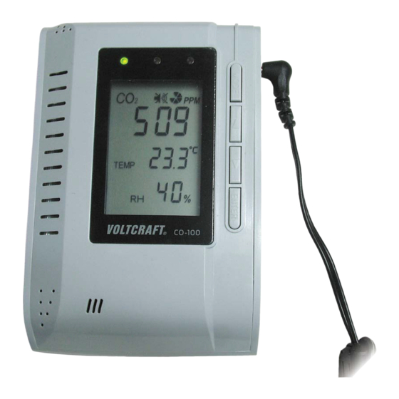
6. BEDIENELEMENTE A LC-Display B Grüne LED C Gelbe LED D Rote LED E Taste „MODE“ F Taste „“ G Taste „“ H Taste „ENTER“ I Löcher für Wandmontage J Niederspannungsbuchse/Stromversorgung K RJ45-Buchse (nur für den Hersteller) L Öffnung für Gasmessung M Klemmenblock für Stromversorgung und Relaisausgang... -
Page 9: Wandmontage Und Anschluss
7. WANDMONTAGE UND ANSCHLUSS Um das CO -Messgerät stationär zu betreiben, kann es über entsprechende Löcher an der Rückseite z.B. an einer Wand montiert werden. Achten Sie dabei darauf, dass die Öffnung für die Gasmessung (siehe Kapitel 6, Position „L“) frei liegt und nicht blockiert wird. Weiterhin muss in der Nähe des CO -Messgeräts eine Steckdose vorhanden sein. - Page 10 • An der Klemmleiste (siehe Kapitel 6, Position „M“) steht ein Relaisausgang zur Verfügung. Das Relais wird aktiviert, wenn der obere Grenzwert 2 (siehe Kapitel 9 c) überschritten wird (rote LED leuchtet auf). Das Relais funktioniert damit als NO-Kontakt (NO = „normally open“ = Schließerkontakt). Die beiden anderen Klemmen können zur Stromversorgung verwendet werden, wenn Sie das mitgelieferte Steckernetzteil nicht anschließen wollen.
-
Page 11: Inbetriebnahme
8. INBETRIEBNAHME • Um das CO -Messgerät in Betrieb zu nehmen, verbinden Sie den Rundstecker des mitgelieferten Steckernetzteils mit der Niederspannungsbuchse seitlich am CO Messgerät und stecken Sie es in eine Netzsteckdose. Wenn Sie die internen Schraubklemmen zur Stromversorgung verwendet haben, so darf das Steckernetzteil nicht angeschlossen werden. -
Page 12: Bedienung
9. BEDIENUNG a) Stummschaltung des Signaltons Bei Überschreiten des oberen CO -Grenzwerts („ALARM2“, siehe Kapitel 9 c), Grundein- stellung ab Werk 1200ppm) wird zusätzlich zum Aufleuchten der roten LED ein lauter Signalton ausgegeben. Für diesen Signalton kann eine Stummschaltung aktiviert werden, z.B. um den Signalton während der Programmierung abzuschalten. -
Page 13: Grenzwert 1 Einstellen
b) Grenzwert 1 einstellen Befindet sich die gemessene CO -Konzentration unterhalb von Grenzwert 1 (Grundeinstel- lung ab Werk 800ppm), so leuchtet die grüne LED. Bei Überschreiten der als Grenzwert 1 eingestellten CO -Konzentration erlischt die grüne LED und die gelbe LED leuchtet auf. Um den Grenzwert 1 einzustellen, gehen Sie wie folgt vor: •... -
Page 14: Höhenlage Einstellen (Höhenkompensation)
d) Höhenlage einstellen (Höhenkompensation) Um korrekte Messwerte zu erhalten, muss die Höhenlage am Betriebsort des CO Messgeräts eingestellt werden. Die Einstellung erfolgt in Höhenmetern bezogen auf Meereshöhe (NN = Normalnull). Gehen Sie wie folgt vor: • Drücken Sie (ausgehend vom normalen Betriebsmodus) so oft kurz die Taste „MODE“, bis im Display „ALTI“... -
Page 15: Kalibrierung
f) Kalibrierung Die Kalibrierung ist bereits durch den Hersteller durchgeführt worden. Trotzdem können Sie eine Kalibrierung selbst vornehmen. Dabei ist aber zu beachten, dass eine neue Kalibrierung nur dann Sinn macht, wenn ein Ihnen bekannter, genauerer Kalibrierwert vorhanden ist! • Sie besitzen ein anderes genau geeichtes CO -Messgerät. -
Page 16: Datenlogger-Funktion (Datenspeicher)
• Nach Abschluss des Kalibriervorgangs wird „PASS“ (Kalibrierung erfolgreich) bzw. „FAIL“ (Kalibrierung fehlerhaft) angezeigt. Eine fehlerhafte Kalibrierung kann vor allem dann auftreten, wenn die CO Konzentration während des Kalibriervorgangs schwankt. Eliminieren Sie jegliche Störeinflüsse und führen Sie dann eine nochmalige Kalibrierung durch. -
Page 17: Max-/Min-Werte Anzeigen/Zurücksetzen
h) MAX-/MIN-Werte anzeigen/zurücksetzen Das CO -Messgerät speichert während dem Betrieb den höchsten bzw. niedrigsten CO Messwert. So können z.B. Spitzenbelastungen schnell festgestellt werden. Dieser Maximum- und Minimumspeicher lässt sich selbstverständlich zurücksetzen. Gehen Sie wie folgt vor: • Drücken Sie (ausgehend vom normalen Betriebsmodus) so oft kurz die Taste „MODE“, bis im Display „MAX MIN“... -
Page 18: Co -Messgerät Auf Werkseinstellungen Zurücksetzen
i) CO -Messgerät auf Werkseinstellungen zurücksetzen Mit dieser Funktion kann das CO -Messgerät auf die Werkseinstellungen zurückgesetzt werden. Dabei werden nicht nur die Einstellungen für die Grenzwerte zurückgesetzt, sondern auch die Grundkalibrierung wieder hergestellt. Außerdem werden alle 48 Datenspeicher (siehe Kapitel 9 g) gelöscht. Gehen Sie wie folgt vor: •... -
Page 19: Temperatur/Belüftungsrate Anzeigen
j) Temperatur/Belüftungsrate anzeigen Die mittlere Displayzeile kann umgeschaltet werden zwischen der Anzeige der Temperatur und der Belüftungsrate. Die Belüftungsrate ist ein Index dafür, wie viel Luft von außen nach innen umgewälzt wird. Die Berechnung erfolgt aufgrund der Änderung der CO -Konzentration in einem bestimmten Zeitraum und dem Unterschied zur CO -Konzentration im Außenbereich... -
Page 20: Wartung Und Pflege
10. WARTUNG UND PFLEGE Das Produkt ist für Sie wartungsfrei, zerlegen Sie es niemals (bis auf die in dieser Bedienungsanleitung beschriebenen Arbeiten für die Montage). Überlassen Sie eine Wartung oder Reparatur einem Fachmann. Für eine Reinigung verwenden Sie nur ein weiches, trockenes und sauberes Tuch. Drücken Sie nicht zu stark auf das Display, da dies nicht nur zu Kratzspuren führt, sondern auch zu einer Beschädigung des Displays. -
Page 21: Technische Daten
12. TECHNISCHE DATEN a) CO -Messgerät Allgemein: Betriebsspannung ......6 V/DC Umgebungstemperatur ...... 0 °C bis +50 °C Umgebungsluftfeuchte ...... 0% bis 95% relative Luftfeuchte, nicht kondensierend Relais-Belastbarkeit ......max. 30 V/DC, 2 A Gewicht ..........180 g Abmessungen ........siehe Abbildung 30 mm 30 mm 85 mm... -
Page 22: Steckernetzteil
-Sensor: Messbereich ........0 - 3000ppm Auflösung ........... 1ppm bei 0 - 1000ppm 5ppm bei 1001 - 2000ppm 10ppm bei 2001 - 3000ppm Genauigkeit ........±75ppm (oder ±5%) bei 0 - 2000ppm ±7% bei >2000ppm (Angaben gelten für einen Zeitraum von 5 Jahren) Wiederholbarkeit ........ - Page 23 TABLE OF CONTENTS Page 1. Introduction ........................24 2. Intended Use ........................25 3. Scope of Delivery ......................26 4. Explanation of Symbols ....................26 5. Safety Information ......................27 6. Controls Elements ......................29 7. Wall Installation and Connection ................... 30 8.
-
Page 24: Introduction
Whether you are an ambitious hobby electronics technician or a professional user - a product of the Voltcraft® brand family will provide you with the best solution for even the most sophisticated of tasks. Special features: We offer the sophisticated technology and reliable quality of our Voltcraft®... -
Page 25: Intended Use
2. INTENDED USE The product is a stationary CO meter for determination of the carbon dioxide concentration (CO ) in the ambience air with the precise and long-term stable NDIR measuring method (non-dispersive infrared absorption measurement). The meter is used to monitor the carbon dioxide content in the room air so that the corresponding ventilation measures can be initiated early on. -
Page 26: Scope Of Delivery
3. SCOPE OF DELIVERY • CO meter • Mains adapter • Operating instructions 4. EXPLANATION OF SYMBOLS The triangle containing a lightning symbol warns against danger of electric shock or impairment of the electrical safety of the device. An exclamation mark in a triangle indicates important notes in these operating instructions that should be strictly observed. -
Page 27: Safety Information
5. SAFETY INFORMATION In case of damage caused by non-compliance with these operating instructions, the warranty/guarantee will expire. We do not assume any liability for consequential damage! We do not assume any liability for damage to property or personal injury caused by improper use or the failure to observe the safety instructions! In such cases the warranty/guarantee will expire. - Page 28 If you are not sure about the correct operation or if questions arise which are not covered by the operating instructions, please do not hesitate to contact us or another specialist. Voltcraft®, Lindenweg 15, D-92242 Hirschau, Phone +49 180/586 582 7.
-
Page 29: Controls Elements
6. CONTROLS ELEMENTS A LC display B Green LED C Yellow LED D Red LED E „MODE“ button F „“ button G „“ button H „ENTER“ button I Holes for wall-mounting J Low-voltage socket/power supply K RJ45 socket (for the manufacturer only) L Gas measurement aperture M Terminal block for power supply and relay output... -
Page 30: Wall Installation And Connection
7. WALL INSTALLATION AND CONNECTION To operate the CO meter stationarily it can be mounted, e.g. on a wall, using the corresponding holes on its rear. Observe that the gas measurement aperture (see chapter 6, item „L“) is free and not blocked. - Page 31 • A relay output is available at the terminal strip (see chapter 6, item „M“). The relay is activated when the upper threshold 2 (see chapter 9 c) is exceeded (red LED lights up). The relay therefore works as a NO contact (NO = „normally open“ = closer contact). The two other terminals can be used for power supply if you do not wish to connect the included mains adapter.
-
Page 32: Start-Up
8. START-UP • To take the CO meter into operation, connect the round plug of the included mains adapter to the low-voltage socket at the side of the CO meter, and plug it in a mains socket. If you have used the internal screw terminals for power supply, the mains adapter must not be connected. -
Page 33: Operation
9. OPERATION a) Muting the Signal Sound When the upper CO threshold is exceeded („ALARM2“, see chapter 9 c), factory settings 1200ppm), a loud signal sound is emitted in addition to the red LED lighting up. This signal sound can be muted, e.g. to switch it off during programming. Proceed as follows: •... -
Page 34: Setting Threshold Value 1
b) Setting Threshold Value 1 If the measured CO concentration is below threshold value 1 (factory settings 800ppm), the green LED is lit. When the CO concentration set as threshold value 1 is exceeded, the green LED goes out and the yellow LED lights up. Set threshold value 1 as follows: •... -
Page 35: Setting Altitude (Altitude Compensation)
d) Setting Altitude (Altitude Compensation) To receive correct values from your measurements, the altitude at the operating site of the meter must be set. The setting uses altitude meters referring to sea level (NN = sea level). Proceed as follows: •... -
Page 36: Calibration
f) Calibration Calibration was already performed by the manufacturer. nevertheless, you can perform calibration again yourself. Observe that new calibration only makes sense if a more precise value for calibration is known to you! • You have another, precisely calibrated CO meter. -
Page 37: Datalogger Function (Data Memory)
Defective calibration can occur in particular if the CO concentration fluctuates during calibration. Eliminate any interfering influences and perform calibration again. • Briefly press „ENTER“ to leave calibration mode. The CO meter returns to normal display. g) Datalogger Function (Data Memory) The CO meter automatically stores the measured CO (carbon dioxide), temperature and... -
Page 38: Displaying/Resetting Max/Min Values
h) Displaying/Resetting MAX/MIN Values In operation, the CO meter stores the highest and lowest CO value measured. This enables, e.g., quick determination of peak loads. This maximum and minimum memory can, of course, be reset. Proceed as follows: • Briefly press the „MODE“ button repeatedly (from the normal operating mode) until „MAX MIN“... -
Page 39: Resetting The Co Meter To Factory Settings
i) Resetting the CO Meter to Factory Settings This function resets the CO meter to factory settings. Not only the threshold value settings, but also basic calibration is reset. All 48 data memory slots (see chapter 9 g) are also deleted. Proceed as follows: •... -
Page 40: Displaying Temperature/Ventilation Rate
j) Displaying Temperature/Ventilation Rate The medium display line can be switched between temperature and ventilation rate display. The ventilation rate indicates how much air is recirculated from outside to the inside. This is calculated from the change of the CO concentration within a certain period and the difference to the CO concentration outside (atmosphere, approx. -
Page 41: Maintenance And Care
10. MAINTENANCE AND CARE The product is maintenance-free for you. Never take it apart (except for mounting as described in these operating instructions). Repair or maintenance work must be carried out by a specialist. Use a soft, dry and clean cloth only for cleaning. Do not press too hard on the display. -
Page 42: Technical Data
12. TECHNICAL DATA a) CO Meter General: Operating voltage ......6 V/DC Ambient temperature ......0 °C to +50 °C Ambient air humidity ......0% to 95% rel. humidity, non-condensing Relay load capacity ......max. 30 V/DC, 2 A Weight ..........180 g Dimensions ........ -
Page 43: Mains Adapter
sensor: Measuring range ........ 0 - 3000ppm Resolution .......... 1ppm at 0 - 1000ppm 5ppm at 1001 - 2000ppm 10ppm at 2001 - 3000ppm Accuracy ..........±75ppm (or ±5%) at 0 - 2000ppm ±7% at >2000ppm (Data applies for a period of 5 years) Reproducibility ........ - Page 44 TABLE DES MATIÈRES Page 1. Introduction ........................45 2. Utilisation conforme ......................46 3. Contenu de la livraison ....................47 4. Explication des symboles ....................47 5. Consignes de sécurité ....................48 6. Éléments de commande ....................50 7. Montage mural et raccordement ..................51 8.
-
Page 45: Introduction
1. INTRODUCTION Chère cliente, cher client, Vous avez pris une très bonne décision en achetant un produit Voltcraft® et nous vous en remercions. Voltcraft® – Dans le domaine de la technique de mesure, de charge, ainsi que de techni- que de réseau, ce nom représente des produits de qualité supérieure qui se distinguent par une compétence technique, une extraordinaire performance et une innovation perma-... -
Page 46: Utilisation Conforme
2. UTILISATION CONFORME L’appareil est un appareil de mesure portatif du CO qui permet d’enregistrer la concentra- tion de dioxyde de carbone (CO ) dans l’air ambiant à l’aide de la méthode de mesure NDIR précise et stable à long terme (mesure par absorption infrarouge non-dispersive). L’appareil de mesure permet de surveiller la teneur en dioxyde de carbone dans l’air ambiant afin de pouvoir prendre à... -
Page 47: Contenu De La Livraison
3. CONTENU DE LA LIVRAISON • Appareil de mesure du CO • Bloc d’alimentation • Mode d’emploi 4. EXPLICATION DES SYMBOLES Le symbole de l´éclair dans le triangle met en garde contre tout risque d’élec- trocution ou toute compromission de la sécurité électrique de l’appareil. Le symbole avec le point d’exclamation placé... -
Page 48: Consignes De Sécurité
5. CONSIGNES DE SÉCURITÉ Tout dommage résultant du non-respect du présent mode d’emploi entraîne l’annulation de la garantie légale/du fabricant. Nous déclinons toute responsabilité pour les dommages consécutifs ! De même, le constructeur n’assume aucune responsabilité en présence de dommages matériels ou corporels résultant d’une utilisation de l’appareil non conforme aux spécifications ou d’un non-respect des présentes instructions ! De tels cas entraînent l’annulation de la garantie. - Page 49 En cas de doute quant au fonctionnement correct de l’appareil ou si vous avez des ques- tions sans réponse après la lecture du présent mode d’emploi, veuillez nous contacter ou demandez l’avis d’un autre spécialiste. Voltcraft®, Lindenweg 15, D-92242 Hirschau, tél. +49 180/586 582 7.
-
Page 50: Éléments De Commande
6. ÉLÉMENTS DE COMMANDE A Écran LCD B DEL verte C DEL jaune D DEL rouge E Touche « MODE » F Touche « » G Touche « » H Touche « ENTER » I Trous pour le montage mural J Prise basse tension/alimentation électrique K Connecteur RJ45 (réservé... -
Page 51: Montage Mural Et Raccordement
7. MONTAGE MURAL ET RACCORDEMENT Pour exploiter l’appareil de mesure du CO de manière stationnaire, il est par ex. possible de fixer au mur à l’aide des trous prévus à cet effet au dos de l’appareil. Veillez alors à ce que l’orifice pour la mesure du gaz (voir chapitre 6, position « L ») soit dégagé... - Page 52 • Une sortie de relais est disponible sur le bornier (voir chapitre 6, position « M »). Le relais est activé en cas de dépassement (la DEL rouge s’allume) du seuil supérieur 2 (voir chapitre 9 c). Le relais fonctionne alors comme contact NO (NO = « normalement ouvert »...
-
Page 53: Mise En Service
8. MISE EN SERVICE • Pour mettre en service l’appareil de mesure du CO , raccordez la fiche ronde du bloc d’alimentation fourni à la prise basse tension sur le côté de l’appareil de mesure du CO puis enfichez-la dans une prise de courant. Si vous employez les bornes à... -
Page 54: Utilisation
9. UTILISATION a) Mise en veille du signal sonore En cas de dépassement du seuil supérieur de CO (« ALARM2 », voir chapitre 9 c), réglage de base d’usine : 1 200 ppm), la DEL rouge s’allume et un puissant signal sonore retentit en plus. -
Page 55: Programmation De La Valeur Limite 1
b) Programmation de la valeur limite 1 Lorsque la concentration de CO mesurée se situe au-dessous du seuil 1 (réglage de base d’usine : 800 ppm), la DEL verte est allumée. En cas de dépassement de la concentration de CO programmée pour le seuil 1, la DEL verte s’éteint et la DEL jaune s’allume. -
Page 56: Réglage De L'altitude (Compensation En Altitude)
d) Réglage de l’altitude (compensation en altitude) Pour obtenir des mesures correctes, l’altitude doit être réglée pour l’emplacement de montage de l’appareil de mesure du CO . Le réglage s’effectue en mètres d’altitude par rapport au niveau de la mer (NN = niveau zéro). Procédez de la manière suivante : •... -
Page 57: Calibrage
f) Calibrage Le calibrage a déjà été effectué par le fabricant. Vous pouvez tout de même vous-même réaliser un calibrage. Veuillez alors noter qu’un nouveau calibrage ne s’avère judicieux qu’à condition que vous connaissiez une valeur de calibrage plus précise ! •... -
Page 58: Fonction Enregistreur (Mémoire De Données)
• Après la fin de l’opération de calibrage, l’indication « PASS » (succès du calibrage) ou « FAIL » (échec du calibrage) s’affiche sur l’écran. Un calibrage incorrect peut notamment se produire lorsque la concentration de CO varie durant l’opération de calibrage. Éliminez toutes perturbations puis répétez le calibrage. -
Page 59: Affichage/Réinitialisation Des Valeurs Max/Min
h) Affichage/réinitialisation des valeurs MAX/MIN Durant l’exploitation, l’appareil de mesure du CO enregistre la valeur maximale et la valeur minimale de CO . Ceci permet par ex. de rapidement déceler les pics de pollution. Vous pouvez bien sûr réinitialiser la mémoire des valeurs maximales et minimales. Procédez de la manière suivante : •... -
Page 60: Réinitialisation De L'appareil De Mesure Du Co
i) Réinitialisation de l’appareil de mesure du CO aux réglages d’usine Cette fonction permet de réinitialiser l’appareil de mesure du CO aux réglages d’usine. Les seuils programmés tout comme le calibrage de base sont alors rétablis. Toutes les 48 plages de mémoire (voir chapitre 9 g) sont alors effacées. Procédez de la manière suivante : •... -
Page 61: Affichage De La Température/Taux De Ventilation
j) Affichage de la température/taux de ventilation La ligne centrale de l’écran peut, au choix, afficher la température ou le taux de ventilation. Le taux de ventilation est un indice qui indique la quantité d’air qui circule de l’extérieur vers l’intérieur. Le calcul s’effectue en se basant sur l’évolution de la concentration de CO au cours d’une période définie et sur l’écart par rapport à... -
Page 62: Maintenance Et Entretien
10. MAINTENANCE ET ENTRETIEN Le produit ne nécessite aucun entretien. Ne le démontez jamais (sauf pour les travaux décrits dans le présent mode d’emploi). Confiez les travaux d’entretien et de réparation à un spécialiste. Pour le nettoyage, utilisez uniquement un chiffon doux, sec et propre. N’appuyez pas trop fort sur l’écran, ceci pourrait rayer ou endommager l’écran. -
Page 63: Caractéristiques Techniques
12. CARACTÉRISTIQUES TECHNIQUES a) Appareil de mesure du CO Généralités : Tension de service ....6 V/CC Température ambiante ..... 0 °C à +50 °C Humidité de l’air ambiant ..0 % à 95 % d’humidité relative de l’air, sans condensation Capacité... -
Page 64: Bloc D'alimentation
Sonde de CO Plage de mesure ......... 0 á 3 000 ppm Résolution ........... 1 ppm entre 0 et 1 000 ppm 5 ppm entre 1001 et 2 000 ppm 10 ppm entre 2001 et 3 000 ppm Précision ............. ±75 ppm (ou ±5 %) entre 0 et 2 000 ppm ±7 % au-delà... - Page 65 INHOUDSOPGAVE Pagina 1. Inleiding ........................... 66 2. Voorgeschreven gebruik ....................67 3. Leveringsomvang ......................68 4. Verklaring van symbolen ....................68 5. Veiligheidsvoorschriften ....................69 6. Bedieningselementen ..................... 71 7. Wandmontage en aansluiting ..................72 8. Ingebruikname ........................ 74 9.
-
Page 66: Inleiding
1. INLEIDING Geachte klant, Wij danken u hartelijk voor het aanschaffen van een Voltcraft®-product. Hiermee heeft u een uitstekend apparaat in huis gehaald. Voltcraft® - deze naam staat op het gebied van meettechniek, laadtechniek en voedings- spanning voor onovertroffen kwaliteitsproducten die worden gekenmerkt door gespeciali- seerde vakkundigheid, buitengewone prestaties en permanente innovaties. -
Page 67: Voorgeschreven Gebruik
2. VOORGESCHREVEN GEBRUIK Het product is een stationair CO -meetapparaat voor het bepalen van de koolstofdioxideconcentratie (CO ) in de omgevingslucht aan de hand van de nauwkeurige en stabiele NDIR-meetmethode (Niet-Dispersieve-Infrarood-Absorptiemeting). Het meetapparaat dient om het koolstofdioxidegehalte in de kamerlucht te bewaken om vroegtijdig passende maatregelen voor de verluchting te kunnen nemen. -
Page 68: Leveringsomvang
3. LEVERINGSOMVANG • CO -meetapparaat • Netadapter • Gebruiksaanwijzing 4. VERKLARING VAN SYMBOLEN Een bliksemschicht in een driehoek waarschuwt voor een elektrische schok of een veiligheidsbeperking van elektrische onderdelen in het apparaat. Het symbool met het uitroepteken in een driehoek wijst op belangrijke aanwij- zingen in deze gebruiksaanwijzing die in ieder geval moeten worden opge- volgd. -
Page 69: Veiligheidsvoorschriften
5. VEILIGHEIDSVOORSCHRIFTEN Bij beschadigingen veroorzaakt door het niet opvolgen van deze ge- bruiksaanwijzing vervalt ieder recht op garantie! Voor vervolgschade die hieruit ontstaat, zijn wij niet aansprakelijk! Voor materiële schade of persoonlijk letsel, veroorzaakt door ondeskun- dig gebruik of het niet opvolgen van de veiligheidsaanwijzingen, aan- vaarden wij geen aansprakelijkheid! In zulke gevallen vervalt de garantie. - Page 70 Bij vragen met betrekking tot het correcte gebruik of met betrekking tot problemen waar u in de gebruiksaanwijzing geen oplossing voor kunt vinden, contact opnemen met ons of met een andere vakman. Voltcraft®, Lindenweg 15, D-92242 Hirschau, Tel. +49 180/586.582 7.
-
Page 71: Bedieningselementen
6. BEDIENINGSELEMENTEN A LC-display B Groene LED C Gele LED D Rode LED E Toets “MODE” F Toets ”" G Toets “” H Toets “ENTER” I Gaten voor wandmontage J Laagspanningsbus/stroomvoorziening K RJ45-bus (alleen voor de fabrikant) L Opening voor gasmeting M Klemmenblok voor stroomvoorziening en relaisuitgang... -
Page 72: Wandmontage En Aansluiting
7. WANDMONTAGE EN AANSLUITING Om het CO -meetapparaat stationair te gebruiken kan het via overeenkomstige openingen aan de achterzijde vb. aan een muur worden gemonteerd. Let daarbij op dat de opening voor de gasmeting (zie hoofdstuk 6, positie “L”) vrij ligt en niet wordt geblokkeerd. - Page 73 • Aan de klemmenlijst (zie hoofdstuk 6, positie “M”) is een relaisuitgang beschikbaar. Het relais wordt geactiveerd wanneer de bovenste grenswaarde 2 (zie hoofdstuk 9 c) wordt overschreden (rode LED licht op). Het relais functioneert daarmee als NO-contact (NO = “normally open” = werkcontact). De beide andere klemmen kunnen voor de stroomvoorziening worden gebruikt wanneer u de meegeleverde netadapter niet wilt aansluiten.
-
Page 74: Ingebruikname
8. INGEBRUIKNAME • Om het CO -meetapparaat in gebruik te nemen, verbindt u de rondstekker van de meegeleverde netadapter met de laagspanningsbus lateraal aan het CO -meetapparaat en verbindt u het met een contactdoos. Wanneer u voor de stroomvoorziening de interne schroefklemmen heeft gebruikt, mag de netadapter niet worden aangesloten. -
Page 75: Bediening
9. BEDIENING a) Signaaltoon stilleggen Bij het overschrijden van de bovenste CO -grenswaarde (“ALARM2”, zie hoofdstuk 9 c), basisinstelling af fabriek 1200ppm) wordt bovendien bij het oplichten van de rode LED een luide signaaltoon weergegeven. Deze signaaltoon kan worden stilgelegd, vb. om de signaaltoon tijdens het programmeren uit te schakelen. -
Page 76: Grenswaarde 1 Instellen
b) Grenswaarde 1 instellen Als de gemeten CO -concentratie zich onder de grenswaarde 1 (basisinstelling af fabriek 800ppm) bevindt, dan licht de groene LED op. Bij het overschrijden van de als grens- waarde 1 ingestelde CO -concentratie, dooft de groene LED uit en licht de gele LED op. Om de grenswaarde 1 in te stellen, gaat u als volgt te werk: •... -
Page 77: Hoogte Instellen (Hoogtecompensatie)
d) Hoogte instellen (hoogtecompensatie) Om correcte meetwaarden te bekomen, moet de hoogte op de gebruiksplaats van het -meetapparaat worden ingesteld. De instelling gebeurt in meters met betrekking tot de hoogte op zeeniveau (NN = normaal peil). Ga als volgt tewerk: •... -
Page 78: Kalibrering
f) Kalibrering De kalibrering is reeds door de fabrikant uitgevoerd. Toch kunt u zelf een kalibrering uitvoeren. Daarbij moet u er echter op letten dat een nieuwe kalibrering alleen zinvol is, wanneer een u gekende, nauwkeurige kalibreerwaarde aanwezig is! • U bezit een ander, nauwkeurig geijkt CO -meetapparaat. -
Page 79: Datalogger-Functie (Geheugen)
• Na het afsluiten van het kalibreerproces wordt “PASS” (kalibrering succesvol) of “FAIL” (kalibrering mislukt) weergegeven. Een foutieve kalibrering kan vooral optreden, wanneer de CO -concentratie tijdens het kalibreringsproces schommelt. Elimineer alle storende invloeden en voer dan de kalibrering nogmaals uit. •... -
Page 80: Max/Min Waarden Weergeven/Terugzetten
h) MAX/MIN waarden weergeven/terugzetten Het CO -meetapparaat slaat tijdens de werking de hoogste of laagste CO -meetwaarde op. Zo kunt u vb. piekbelastingen snel vaststellen. Dit maximum- en minimumgeheugen kan uiteraard worden teruggezet. Ga als volgt tewerk: • Druk (uitgaand van de normale bedrijfsmodus) kort op de toets “MODE” tot op het display “MAX MIN”... -
Page 81: Co -Meetapparaat Terugzetten Naar Fabrieksinstellingen
i) CO -meetapparaat terugzetten naar fabrieksinstellingen Met deze functie kan het CO -meetapparaat naar de fabrieksinstellingen worden terugge- zet. Daarbij worden niet alleen de instellingen voor de grenswaarden teruggezet, maar ook de basiskalibrering opnieuw opgemaakt. Bovendien worden alle 48 geheugenplaatsen (zie hoofdstuk 9 g) gewist. Ga als volgt tewerk: •... -
Page 82: Temperatuur/Verluchtingsrate Weergeven
j) Temperatuur/verluchtingsrate weergeven De middelste displaycel kan worden omgeschakeld tussen de weergave van de tempera- tuur en het verluchtingsrate. Het verluchtingsrate is een index voor hoeveel lucht van buiten naar binnen wordt gezo- gen. De berekening gebeurt op basis van de wijziging van de CO -concentratie in een bepaalde periode en het verschil tot de CO -concentratie buiten (atmosfeer, ca. -
Page 83: Onderhoud En Verzorging
10. ONDERHOUD EN VERZORGING Het product is voor u onderhoudsvrij. U mag het nooit openen (uitgezonderd voor de in deze gebruiksaanwijzing beschreven werkzaamheden voor de montage). Het product mag alleen door een vakman gerepareerd en onderhouden worden. Reinig het product alleen met een schone, zachte en droge doek. Druk niet te sterk op het display zodat er geen krassporen voorkomen en het display niet wordt beschadigd. -
Page 84: Technische Gegevens
12. TECHNISCHE GEGEVENS a) CO -meetapparaat Algemeen: Voedingsspanning ....6 V/DC Omgevingstemperatuur ... 0 °C tot +50 °C Omgevingsluchtvochtigheid: ... 0% tot 95% relatieve luchtvochtigheid, niet condenserend Relais-belastbaarheid ....max. 30 V/DC, 2 A Gewicht ........180 g Afmetingen ....... zie afbeelding 30 mm 30 mm 85 mm... -
Page 85: Netadapter
-sensor: Meetbereik ......... 0 - 3000ppm Resolutie ..........1ppm bij 0 - 1000ppm 5ppm bij 1001 - 2000ppm 10ppm bij 2001 - 3000ppm Nauwkeurigheid ......... ±75ppm (of ±5%) bij 0 - 2000ppm ±7% bij >2000ppm (Gegevens gelden voor een periode van 5 jaar) Herhaalbaarheid ........ -
Page 88: Legal Notice
Information légales Ce mode d'emploi est une publication de la société Voltcraft®, Lindenweg 15, D-92242 Hirschau/Allemagne, Tél. +49 180/586 582 7 (www.voltcraft.de). Tous droits réservés, y compris de traduction. Toute reproduction, quelle qu'elle soit (p. ex. photocopie, microfilm, saisie dans des installations de traitement de données) nécessite une autorisation écrite de l'éditeur.