Siemens RWF40 Manuel D'entretien
Régulateur de puissance
Masquer les pouces
Voir aussi pour RWF40:
- Mode d'emploi (8 pages) ,
- Notice technique (14 pages) ,
- Mode d'emploi (56 pages)
Table des Matières
Liens rapides
Istruzioni per installazione, uso e manutenzione
Anleitungen für Einbau, Betrieb und Wartung
Installation, use and maintenance instructions
Manuel d'entretien
Regolatore di potenza
I
Leistungsregler
D
Power controller
GB
Régulateur de puissance
F
RWF40
CODICE - CODE
3010210
3010211
3010212
3010220
3001074
3001078
3010356
3010357
3010414
3010417
2915724 (11) - 09/2008
Table des Matières

Manuels Connexes pour Siemens RWF40


Sommaire des Matières pour Siemens RWF40
- Page 1 Istruzioni per installazione, uso e manutenzione Anleitungen für Einbau, Betrieb und Wartung Installation, use and maintenance instructions Manuel d’entretien Regolatore di potenza Leistungsregler Power controller Régulateur de puissance RWF40 CODICE - CODE 3010210 3010211 3010212 3010220 3001074 3001078 3010356 3010357...
-
Page 2: Table Des Matières
ACCESSO AL REGOLATORE RWF40....16 ZUGRIFF ZUM REGLER RWF40......17 MODALITÀ... -
Page 3: Schema Di Principio
SCHEMA DI PRINCIPIO DEI DISPOSITIVI COLLEGABILI AL REGOLATORE DI POTENZA RWF40 STROMLAUFSCHALTPLAN DER AN LEISTUNSREGLER RWF40 ANSCHLIEßBAREN VORRICHTUNGEN GENERAL WIRING DIAGRAM OF THE DEVICES THAT CAN BE CONNECTED TO THE RWF40 POWER CONTROLLER SCHÉMA DE PRINCIPE DES DISPOSITIFS QUI POUVANT ÊTRE RELIÉS AU REGULATEUR DE PUISSANCE RWF40... -
Page 4: Dati Tecnici
DATI TECNICI Regolatore di potenza ......RWF40.000.A97 (Versione LOW) - RWF40.002.B97 (Versione HIGH) Tensione di alimentazione . - Page 5 E' un apparecchio universale, configurabile, che può essere collegato alle seguenti sonde: Parametro da controllare Sonda Temperatura Termoresistenza Pt100, Pt1000 -200... 850 °C Ni100, Ni1000 DIN 43760 -60... 250 °C Ni1000 Landis & Staefa -50... 160 °C Termocoppia -200... 1000 °C -200...
-
Page 6: Technische Angaben
Leistungsregler........RWF40.000.A97 (Ausführung... - Page 7 Es handelt sich um ein konfigurierbares Universalgerät, das an folgende Fühler angeschloßen werden kann: Regelparameter Fühler Temperatur Thermowiderstand Pt100, Pt1000 -200... 850 °C Ni100, Ni1000 DIN 43760 -60... 250 °C Ni1000 Landis & Staefa -50... 160 °C Thermoelement -200... 1000 °C -200...
-
Page 8: Technical Data
Power controller ........RWF40.000.A97... - Page 9 It is a universal, configurable device and can be connected to the following probes: Parameter to be controlled Probe Temperature Thermal resistance Pt100, Pt1000 -200... 850 °C Ni100, Ni1000 DIN 43760 -60... 250 °C Ni1000 Landis & Staefa -50... 160 °C Thermocouple -200...
-
Page 10: Données Techniques
DONNÉES TECHNIQUES Régulateur de puissance ......RWF40.000.A97 (Version LOW) - RWF40.002.B97 (Version HIGH) Tension d’alimentation ......110...240 V + / - 10 % Fréquence . -
Page 11: Paramètre À Contrôler
C’est un appareil universel, configurable, qui peut être relié aux sondes suivantes: Paramètre à contrôler Sonde Température Thermomètre à résistance Pt100, Pt1000 -200... 850 °C Ni100, Ni1000 DIN 43760 -60... 250 °C Ni1000 Landis & Staefa -50... 160 °C Thermocouple -200... -
Page 12: Impiego
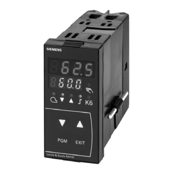
D914 pressione. DESCRIZIONE (C) La figura (C) mostra RWF40 nelle condizioni di funzionamento, in cui viene visualizzato il display di base, che indica il valore reale ed il setpoint at- SIEMENS tivo al momento. Da questa condizione possono essere attivati il funzionamento manuale, l’... -
Page 13: Use
BESCHREIBUNG (C) DESCRIPTION (C) Das Bild (C) zeigt den RWF40 nach dem Ein- DESCRIPTION (C) Figure (C) shows the RWF40 after switching on, schalten der Spannungsversorgung. Dieser Zu- where the basic display is shown indicating the Le figure (C) montre RWF40 après la mise sous... -
Page 14: Installazione
! APPLICAZIONE SUL BRUCIATORE (A) - (B) - (C) - (D) - (E) I bruciatori sono già predisposti per accogliere il regolatore di potenza RWF40. Il codice 3010212 va inserito nella staffa 1)(A) del bruciatore e fissato con le due viti 2)(A) dopo aver inserito le piastrine 3)(A). -
Page 15: Installation
(A) - (B) - (C) - (D) - (E) Die Brenner sind bereits für den Einbau des Les brûleurs sont déjà conçus pour recevoir le The burners are preset to accept the RWF40 Leistungsreglers RWF40 vorbereitet. régulateur de puissance RWF40. -
Page 16: Applicazione A Quadro
• Il filo di terra deve essere il più corto possibile. ACCESSO AL REGOLATORE RWF 40 (C) D918 Il regolatore RWF40 ha tre livelli di accesso: 1° : Livello utente E' il livello di funzionamento. I display 1 e 2, fig. (C) pag.12, visualizza- no le informazioni. -
Page 17: Mounting On The Control Panel
• Der Erdleiter muß so kurz als möglich sein. • Le fil de mise à la terre doit être le plus court CONTROLLER (C) possible. The RWF40 controller has three access levels: ZUGRIFF ZUM REGLER RWF40 (C) 1° : User level ACCES AU REGULATEUR Der Regler RWF40 hat drei Geräteebenen:... -
Page 18: Modalità Di Impostazione
MODALITÀ DI IMPOSTAZIONE DEL REGOLATORE RWF40 Una corretta taratura del regolatore RWF40 richiede una conoscenza approfondita, che può essere acquisita attraverso una attenta let- tura del presente manuale. Il regolatore dispone di una funzione di autoacquisizione dei parametri da controllare “tunE” che determina automaticamente le variabili di processo. -
Page 19: Einstellung Des Reglers
EINSTELLUNG DES REGLERS RWF40 Für eine korrekte Eichung des Reglers RWF40 ist eine gründliche Kenntnis erforderlich, zu der man nur durch genaues Lesen der vorlie- genden Anleitung gelangt. Der Regler verfügt über eine Selbsteinstellfunktion der zu überprüfenden Parameter, “tunE” genannt, die das automatische Erfassen der Prozessvariablen bewirkt. -
Page 20: Setting Mode Of The Rwf40 Controller
SETTING MODE OF THE RWF40 CONTROLLER The correct setting of the RWF40 controller requires thorough knowledge, which can be acquired by carefully reading this manual. The controller has a facility for the auto-acquisition of the parameters to be controlled “tunE”, which automatically determines the process variables. -
Page 21: Modalite Pour La Saise Du Regulateur Rwf40
MODALITE POUR LA SAISE DU REGULATEUR RWF40 Le réglage correct du régulateur RWF40 demande une connaissance approfondie qui peut être acquise en lisant attentivement ce manuel. Le régulateur dispose d’une fonction d’autoréglage des paramètres à contrôler “tunE” qui détermine automatiquement les variables de processus. -
Page 22: Livello: Livello Utente
è stata impostata. ! Ritorno alla regolazione automatica pre- mendo per 5 s DATI DI PROCESSO EXIT SIEMENS PROZESSDATEN Attenzione. Quando si attiva il funzionamento PROCESS DATA manuale, la posizione del servomotore è DONNÉES DU PROCESSUS impostata a 0 finchè non viene modificata con gli appositi tasti. -
Page 23: Level: User Level
BEDIENEREBENE USER LEVEL NIVEAU OPÉRATEUR 1° Ebene - 1° level - 1° niveau - Diese Ebene wird aus der Normalanzeige heraus This level is started from the basic display. Set- Ce niveau est lancé à partir de l’affichage nor- mal. On peut modifier les valeurs de consigne gestartet. -
Page 24: Relè K1 - K2 - K3 - K6
IL REGOLATORE RWF40 È DOTATO DI 4 LIVELLO PARAMETRI SIEMENS RELÈ: k1 - k2 - k3 - k6 (vedi schema a pag. 3). PARAMETEREBENE La loro funzione è la seguente: PARAMETER LEVEL k1 : E' un relè che l'installatore può utilizzare in NIVEAU PARAMÉTRAGE... -
Page 25: Relays K1 - K2 - K3 - K6
DER REGLER RWF40 IST MIT 4 RELAIS THE RWF40 CONTROLLER IS EQUIPPED LE REGULATEUR RWF40 EST MUNI DE 4 AUSGERÜSTET: k1 - k2 - k3 - k6 WITH FOUR RELAYS: k1 - k2 - k3 - k6 RELAIS: k1 - k2 - k3 - k6 (siehe Schaltplan auf Seite 3). -
Page 26: Modi Operativi
HYS3 Setpoint, valore di consegna della grandezza Betrieb controllata HYS1 Istwert zwischen HYS1 und HYS3 Il regolatore di potenza RWF40 può funzionare in due modi: Modulating and 2-position • funzionamento al minimo; operation • funzionamento in potenza; Actual value between HYS1 and HYS3 Funzionamento al minimo (A) Fonctionnement modulant et à... -
Page 27: Operating Modes
Set-point, valeur de consigne de la grandeur erten Regelgröße ist, value contrôlée kann der Leistungsregler RWF40 auf zwei Arten The RWF40 power controller can operate in two Le régulateur de puissance RWF40 peut fonc- funktionieren. Mit: ways. With: tionner de deux façons différentes, c’est-à-dire: •... -
Page 28: Bruciatore Bistadio, Uscita A 3 Punti
Bruciatore bistadio, uscita a 3 punti (A) Nella parte (1) del diagramma (A), è attiva la fun- zione termostato. HYS3 Nella parte (2), un regolatore a due posizioni HYS2 opera sul secondo stadio, inserendolo al rag- HYS1 giungimento del differenziale inferiore "HYS1" e disinserendolo al differenziale "HYS2", attraver- so i relè... -
Page 29: Two-Stage Burner, 3-Position Output
Brenner 2-stufig, 3-Punktausgang (A) Two-stage burner, 3-position output (A) Brûleur 2 allures, sortie 3 points (A) Dans la zone (1) du schéma (A), la fonction ther- Im Bereich (1) des Bildes ist die Thermostatfunk- In area (1) of diagram (A), the thermostat func- mostat est active. -
Page 30: Descrizione Parametri
DESCRIZIONE PARAMETRI H maggiore H größer greater H SCL - SCH Setpoint (°C) H supérieure Sollwert (°C) SCL ed SCH sono i limiti inferiore e superiore del Setpoint (°C) campo di regolazione della grandezza regolata Valeur de consigne (°C) X. Quando la grandezza X raggiunge questi limiti interviene il relè... -
Page 31: Description Of The Parameters
DESCRIPTION DES PARAMETRES BESCHREIBUNG DER PARAMETER DESCRIPTION OF THE PARAMETERS SCL - SCH SCL - SCH SCL - SCH SCL und SCH sind die Limitkontakte unten und SCL and SCH are the lower and upper limits of SCL et SCH sont les limites inférieure et oben des Regelbereichs der Größe X. - Page 32 Nota: - Parametri Pb.1 - rt - dt Con la definizione di questi tre parametri si pre- dispone il funzionamento del bruciatore secondo le esigenze dell'impianto. Il regolatore RWF40 attua una regolazione di tipo PID, dove: P = Proporzionale = Integrale D = Derivativo Pb.1...
- Page 33 Der Regler RWF40 führt eine PID Regelung aus, The RWF40 controller actuates a PID type ad- Note: - Paramètres Pb.1 - rt - dt justment, where: En définissant ces trois paramètres on prévoit le...
- Page 34 Azione integrale Come abbiamo visto, l'azione proporzionale compensa in breve tempo lo scostamento della grandezza regolata X senza però riuscire a ripor- tarla al valore prescritto W. Questo significa che viene mantenuto uno scostamento permanente fra grandezza regolata X e valore prescritto W. Interviene allora l'azione integrale che agisce solo sul residuo scostamento rimasto (scostamento permanente) per riportare la grandezza regolata...
- Page 35 Integralwirkung Integral action Action intégrale Wie untersucht, gleicht die Proportionalwirkung As we have seen, proportional action compen- Comme nous l’avons vu, l’action proportionnelle die Abweichung der Regelgröße X in kurzer Zeit sates the deviation of the controlled quantity X in compense rapidement l’écart de la grandeur aus, ohne daß...
-
Page 36: Livello: Livello Configurazione
LIVELLO CONFIGURAZIONE SIEMENS KONFIGURATIONSEBENE Zona neutra CONFIGURATION LEVEL E' la zona con assenza di comandi al servomo- NIVEAU CONFIGURATION tore. Viene espressa in percentuale del campo di regolazione della sonda impiegata e si colloca a cavallo del valore impostato W. -
Page 37: Level: Configuration Level
Schaltpunktabstand Neutral area Zone neutre Es ist die Zone, wo keine Schaltungen zum Stel- This area has no controls for the servomotor. It is Il s’agit de la zone avec absence de commandes lantrieb hin vorhanden sind. Als Prozentsatz des expressed as a percentage of the adjustment au servomoteur. -
Page 38: Configurazione C111
CONFIGURAZIONE - KONFIGURATION - CONFIGURATION - CONFIGURATION SIEMENS 0000 C111 C111 ingressi C111 Eingänge C111 inputs C111 entrées Ingresso analogico 1 - Analogeingang 1 - Analog input 1 - Entrée analogique 1 Pt100, 3 fili / 3 Leiter / 3-wire / 3 fils... -
Page 39: Configurazione C112 - C113
C112 contatto ausiliario, tipo regolatore, setpoint “SP1”, blocco SIEMENS C112 Limitkomparator, Reglerart, Sollwert “SP1”, Verriegelung 0000 C112 auxiliary contact, controller type, setpoint “SP1”, locking C112 comparateur de limites, type de régulateur, consigne “SP1”, verrouillage C112 Contatto ausiliario - Limitkomparator - Auxiliary contact - Comparateur de limites Nessuna funzione (lk off) - Ohne Funktion (lk aus) - No function (lk off) - Sans fonction (lk hors) lk1, ingresso / Eingang / input / entrée 1... -
Page 40: Affinamento Della Regolazione
AFFINAMENTO DELLA REGOLAZIONE Come abbiamo visto, il regolatore RWF40 ha la capacità di controllare con continuità la potenza del bruciatore secondo le più svariate mutazioni del carico della caldaia, o di altro generatore. La difficoltà sta nel saper proporzionare il con-... -
Page 41: Adjustment Refinement
ADJUSTMENT REFINEMENT PERFECTIONNEMENT DU REGLAGE Wie bereits gesehen, hat der Regler RWF40 die As we have seen, the RWF40 controller can con- Comme nous l’avons vu, le régulateur RWF40 a Fähigkeit, die Brennerleistung kontinuierlich je tinuously control burner output according to the la capacité... -
Page 42: Funzione "Tune
FUNZIONE “tunE” Il regolatore RWF40 è dotato di una funzione di auto-adattamento “tunE" o autoacquisizione dei parametri di regolazione. Questa funzione permette al regolatore di effettuare autonomamente l'acquisizione dei parametri necessari (Pb1 - rt - dt ecc...) per il controllo e la regolazione del processo. -
Page 43: Funktion "Tune
FUNKTION “tunE” Der Regler ist mit der Selbstoptimierungs- bzw. Selbsteinstellfunktion “tunE” der Regelparameter ausgestattet. Diese Funktion ermöglicht es dem Regler, die Erfassung der für die Kontrolle und Regelung des Prozesses benötigten Parameter (Pb1 - Ti - Td ecc...) autonom durchzuführen. Für eine richtige Selbstoptimierung ist es wichtig, daß der Prozeß keine plötzlichen Schwankungen und Instabilität hat, er darf auch nicht auf konstantem Wert ohne Änderungen sein, außerdem dürfen keine parallel geschalteten Kessel vorhanden sein. -
Page 44: Tune" Function
“tunE” FUNCTION The RWF40 controller has a self-tuning or self-acquisition function of the setting parameters “tunE". This function allows the controller to autonomously acquire the necessary parameters (Pb1 - rt - dt etc) for controlling and setting up the process. -
Page 45: Fonction "Tune
FONCTION “tunE” Le régulateur RWF40 est muni d’une fonction d’auto-réglage “tunE" ou d’acquisition automatique des paramètres de réglage. Cette fonction permet au régulateur d’effectuer, de façon autonome, l’acquisition des paramètres nécessaires (Pb1 - rt - dt etc...) pour le contrôle et le réglage du processus. - Page 46 Verifica dei parametri del regolatore Kontrolle der Reglerparameter L’adattamento ottimale del regolatore al processo può essere verificato Die optimale Anpassung der Regler an die Regelstrecke kann durch registrando un ciclo completo di avviamento. I grafici che seguono evi- Aufzeichnung des Anfahrvorgangs bei geschlossenem Regelkreis denziano i possibili errori di impostazione e le loro azioni di correzione.
- Page 47 Checking the controller parameters Contrôle des paramètres du régulateur The optimum adjustment of the controller to the controlled system can L’adaptation optimale des régulateurs à la boucle de réglage peut être be checked by recording a complete starting cycle. The following dia- vérifiée grâce à...
-
Page 48: Cosa Fare Se
Descrizione Causa / comportamento / rimedio Il display del valore reale (rosso) Superamento verso l’alto o verso il basso del SIEMENS indica "1999" lampeggiante. campo di misura dell’ingresso analogico 1. Il display del setpoint indica il set- Il valore reale non è stato misurato. -
Page 49: Was Ist, Wenn
Merke. Die Erfassung von Messbereichsüber- / -unterschreitung ist vom angeschlossenen Fühler abhängig. Anzeige Beschreibung Ursache / Reglerverhalten / Abhilfe Istwertanzeige (rot) zeigt "1999" Messbereichsüber- oder -unterschreitung auf SIEMENS blinkend an. Analogeingang 1. Sollwertanzeige zeigt den Sollwert Der Istwert wird nicht erfasst und der Regler führt 1999 eine Sicherheitsabschaltung durch. -
Page 50: What To Do If
Note. The detection of measurement range crossings depends on the type of sensor used. Display Description Cause / controller behavior / remedy Actual value display (red) shows Overrange or underrange on analog input 1. SIEMENS "1999" flashing. The actual value has not been measured. Setpoint display shows the set- Controller initiates lockout. 1999 point. -
Page 51: Que Se Passe-T-Il Si
Description Cause / comportement / remède L’affichage de valeur instantanée Dépassement dans un sens ou dans l’autre de la SIEMENS (rouge) clignote et indique "1999". plage de mesure sur l’entrée analogique 1. L’affichage de valeur de consigne La valeur instantanée n’est pas enregistrée et le 1999 indique la consigne. - Page 52 Con riserva di modifiche - Änderungen vorbehalten! - Subject to modifications - Sous réserve de modifications...