Table des Matières
Publicité
Les langues disponibles
Les langues disponibles
Liens rapides
INDOOR GAS TANKLESS WATER HEATER
INDOOR GAS TANKLESS WATER HEATER
SUPPORT@ONSENPRODUCTS.COM
ONSENPRODUCTS.COM
ONSENPRODUCTS.CA
800.996.5559
800.996.5559
14
INSTALLATION AND
OPERATION MANUAL
MANUEL D'INSTALLATION
ET D'UTILISATION
CHAUFFE-EAU RÉSIDENTIEL AU GAZ
CHAUFFE-EAU RÉSIDENTIEL AU GAZ
SANS RÉSERVOIR
SANS RÉSERVOIR
MODEL / MODÈLE : ON-I14L-LP, ON-I14L-NG
MODEL / MODÈLE : ON-I14L-LP, ON-I14L-NG
L
Publicité
Chapitres
Table des Matières
Dépannage

Manuels Connexes pour onsen ON-I14L-LP


Sommaire des Matières pour onsen ON-I14L-LP
- Page 1 ET D’UTILISATION INDOOR GAS TANKLESS WATER HEATER INDOOR GAS TANKLESS WATER HEATER CHAUFFE-EAU RÉSIDENTIEL AU GAZ CHAUFFE-EAU RÉSIDENTIEL AU GAZ SANS RÉSERVOIR SANS RÉSERVOIR MODEL / MODÈLE : ON-I14L-LP, ON-I14L-NG MODEL / MODÈLE : ON-I14L-LP, ON-I14L-NG SUPPORT@ONSENPRODUCTS.COM ONSENPRODUCTS.COM ONSENPRODUCTS.CA 800.996.5559 800.996.5559...
- Page 38 • Si vous ne pouvez pas joindre votre fournisseur de gaz, appelez les pompiers. L’installation et le service pour cet appareil doivent être effectués par un installateur qualifié - agence de services de sécurité ou le fournisseur de gaz. ONSEN ONSEN 2181 RUE DE LA MÉTROPOLE 2181 RUE DE LA MÉTROPOLE...
- Page 39 FRANÇAIS TABLE DES MATIÈRES INTRODUCTION ET AVERTISSEMENTS DE SÉCURITÉ Mesures de securité importantes ................... 40 Consignes de sécurité ...................... 40 OPÉRATION Introduction du produit ....................43 Mode d’emploi ........................43 Arrêt prolongé ........................46 Avertissements en climat froid ..................48 Entretien et inspection ....................
-
Page 40: Mesures De Securité Importantes
INTRODUCTION ET CONSIGNES DE SÉCURITÉ Félicitations pour votre acquisition d’un CHAUFFE-EAU RÉSIDENTIEL AU GAZ SANS RÉSERVOIR ONSEN Afin de garantir une installation adéquate, une utilisation en toute sécurité et une longue durée de vie, veuillez lire attentivement ces instructions. L’installation ne doit être effectuée que par des professionnels certifiés pour assurer une l’installation conforme avec les codes du bâtiment, de plomberie et d’électricité. - Page 41 FRANÇAIS AVERTISSEMENT Si le chauffe-eau doit être installé, déplacé ou requiert un entretien, contactez des professionnels certifiés. Le recours à des professionnels permet de s’assurer que tous les travaux effectués sont pleinement con- formes aux codes du bâtiment, de la plomberie et de l’électricité. Maintenez l’endroit autour de l’appareil dégagée et exempte de matériaux inflammables tels que tissus, bois, aérosols, papier, essence, etc.
- Page 42 La tuyauterie d’échappement est très chaude pendant un certain temps après utilisation. Ne touchez pas le tuyau. Assurez-vous que la neige, la glace ou d’autres débris ne bloquent pas les conduits d’admission ou d’échap- pement. Un entretien régulier doit être effectué dans les endroits autour des appareils de chauffage pour prévenir l’intrusion d’insectes et un éventuel bris de l’équipement.
-
Page 43: Opération
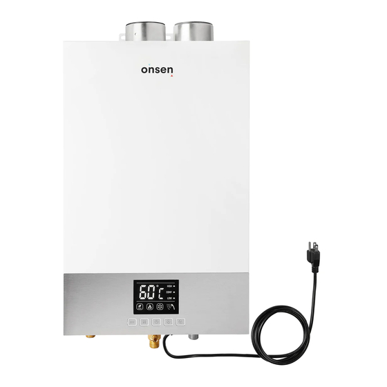
OPÉRATION INTRODUCTION DU PRODUIT Le chauffe-eau résidentiel au gaz sans réservoir Onsen 14L est alimenté au gaz et chauffe l’eau en activant une flamme sur l’échangeur de chaleur en cuivre. L’eau entrante est chauffée lorsqu’elle circule dans la tuyauterie de l’échangeur de chaleur avant d’être dirigée vers la sortie d’eau. -
Page 44: Démarrage De Routine
DÉMARRAGE DE ROUTINE Exécutez la procédure suivante pour un appareil qui a été mis hors service pendant une courte période de temps : Assurez-vous que tous les bouchons de drainage sont installés dans l’unité. Valve d’arrivée d’eau Assurez-vous que tous les points d’utilisation d’eau chaude (robinets, etc.) sont fermés. -
Page 45: Affichage Du Panneau De Contrôle
FRANÇAIS AFFICHAGE DU PANNEAU DE CONTRÔLE Écran LED affiche les informations suivantes : La température définie et la température réelle. L’état de fonctionnement de l’unité. L’unité fonctionne normalement si les symboles de flamme, ventilateur et débit d’eau sont allumés. Le symbole Eco s’affiche lorsqu’on appuie sur le bouton Eco. Les données de sélection de température prédéfinies High, Comf, Low, s’affichent en appuyant sur le bouton Mode. -
Page 46: Prévention De Brûlures
Une fois la température réglée, ouvrez la valve d’eau et observez le comportement de l’appareil. Les symboles de flamme, ventilateur et pommeau de douche devraient s’afficher pour indiquer que la flamme est allumée et que l’unité fonctionne normalement. PRÉVENTION DE BRÛLURES DANGER La température de l’eau au-dessus de 125°... - Page 47 FRANÇAIS Le chauffe-eau et l’eau à l’intérieur de l’appareil peuvent être très chauds. Attendre que l’appareil se refroidisse et soyez prudent lors du drainage afin de minimiser les ATTENTION risques de blessures. Éteindre le chauffe-eau en appuyant sur le bouton « ON/OFF ». Fermer la valve de gaz (A).
-
Page 48: Avertissements En Climat Froid
Bouchons de drainage Sortie d’eau Entrée d’eau Valve de gaz Bouchons de drainage AVERTISSEMENTS EN CLIMAT FROID RISQUES DE DOMMAGES DUS AU GEL ET MESURES DE PRÉCAUTIONS Les températures causant le gel peuvent endommager le chauffe-eau et / ou la tuyauterie d’eau. L’eau gelée prend de l’expansion rapidement et peut créer d’énormes forces mécaniques. -
Page 49: Garantie
FRANÇAIS QUOI FAIRE LORSQU’IL N’Y A PAS DE DÉBIT D‘EAU EN RAISON DE L’APPAREIL GELÉ Fermer la valve de gaz et la valve d’arrivée d’eau. Éteignez l’interrupteur d’alimentation. Ouvrir un robinet d’eau chaude (lavabo, douche, etc.). Ouvrez maintenant la valve d’arrivée d’eau et vérifiez le débit d’eau. S’il n’y a pas d’écoulement, tentez de réchauffer l’appareil en utilisant un séchoir ou tout autre appareil de chauffage électrique portatif. -
Page 50: Liste De Contrôle D'inspection De Routine
LISTE DE CONTRÔLE D’INSPECTION DE ROUTINE Matière inflammable à proximité de l’appareil ou de la tuyauterie d’échappement ? Bruit inhabituel provenant de l’appareil lorsqu’il est en fonction ? Les entrées d’air et les gaz d’échappement sont-ils exempts de tout obstacle ou débris ? Signes de fuite d’eau près de l’appareil ou des tuyaux ? Apparence physique anormale au niveau du boîtier de l’unité... -
Page 51: Maintenance Du Ventilateur
FRANÇAIS Maintenance du ventilateur Le moteur du ventilateur est lubrifié en permanence et ne nécessite pas de lubrification périodique. Si le moteur tombe en panne, il doit être remplacé uniquement par un technicien qualifié. Purger la soupape de sûreté Si une soupape de sûreté se décharge périodiquement, cela peut être dû à l’expansion thermique survenant d’un système d’alimentation en eau à... -
Page 52: Dépannage
En cas de difficultés d’utilisation de votre appareil, veuillez consulter le tableau suivant. Pour de l’aide supplémentaire, veuillez contacter ONSEN en écrivant à support@onsenproduits.ca ou en appelant le 800-996-5559. Veuillez avoir à portée de la main ou fournir les informations sur votre produit, y compris le numéro de série, la preuve d’achat et le code d’erreur s’il est affiché... - Page 53 FRANÇAIS PROBLÈME CAUSE POSSIBLE SOLUTION Il n’y a pas d’écoulement Source de gaz épuisée ou valve La valve de gaz doit être ouverte. d’eau chaude en ouvrant de gaz fermée. Remplir le réservoir de gaz (le cas échéant). un robinet d’eau chaude. Panne de courant.
-
Page 54: Codes De Diagnostic
PROBLÈME CAUSE POSSIBLE SOLUTION Le ventilateur de l’appareil Le ventilateur est conçu pour Aucun. Fonctionnement normal. fonctionne pendant un fonctionner pendant 30 secondes certain temps après l’arrêt après l’arrêt du brûleur de l’appar- du fonctionnement. eil. CODES DE DIAGNOSTIC Chaque fois qu’une panne se produit, une alerte retentit et un code de diagnostic s’affiche pour indiquer le mode de panne au moment de l’événement. - Page 55 FRANÇAIS CODE CAUSE POSSIBLE SOLUTION Problème au niveau du capteur de température d’entrée d’eau. La fiche du capteur n’est pas connectée cor- Reconnectez câblage (CN8) à la carte d’alimenta- rectement ou déconnectée de la carte mère. tion. Le capteur est devenu défectueux (un court- Remplacez le capteur de température.
-
Page 56: Installation
INSTALLATION DIRECTIVES D’INSTALLATION Seul un installateur qualifié doit installer cet équipement. Une installation effectuée par un installateur non qualifié pourrait annuler la garantie. Le non-respect des codes et réglementations nationales et locales relatives à l’installation de cet appareil pourrait également annuler la garantie. Cet appareil ne doit PAS être installé... -
Page 57: Inclus Dans La Boîte
FRANÇAIS Si un chauffe-eau est installé dans un système d’alimentation à circuit fermé, tel qu’un système muni d’un dispositif anti-refoulement dans la conduite d’alimentation en eau froide, des mesures doivent être prévus pour contrôler l’expansion thermique. Contactez le fournisseur d’approvisionnement en eau ou l’inspecteur de plomberie municipale pour connaître les solutions disponibles. -
Page 58: Exigences De Dégagement Entre L'appareil Et Les Matières Combustibles
EXIGENCES DE DÉGAGEMENT ENTRE L’APPAREIL ET LES MATIÈRES COMBUSTIBLES COMPOSITION DU MATÉRIAU ADJACENT Incombustible Combustible Côtés 2 pouces 50 mm 6 pouces 150 mm Haut 2 pouces 50 mm 12 pouces 300 mm 12 pouces 300 mm 12 pouces 300 mm À... -
Page 59: Conduite De Gaz
FRANÇAIS CONDUITE DE GAZ La tuyauterie de gaz doit être dimensionnée, installée et testée uniquement par un professionnel certifié. Une installation incorrecte peut entraîner un mauvais AVERTISSEMENT fonctionnement de l’équipement ou une situation dangereuse. Vérifiez le type de gaz utilisé avant l’installation. NE PAS connecter un appareil si le type de gaz n’est pas compatible avec celui-ci. -
Page 60: Conduites D'eau
CONDUITES D’EAU La tuyauterie ainsi que le matériel de soudure et tous composants connectés à ce chauffe-eau doivent être approuvés pour une utilisation dans les systèmes d’eau potable. Si le chauffe-eau a déjà été utilisé pour chauffer de l’eau non potable, ne jamais l’installez dans un système d’eau potable. -
Page 61: Système D'admission D'air Et D'échappement
FRANÇAIS SYSTÈME D’ADMISSION D’AIR ET D’ÉCHAPPEMENT Une ventilation incorrecte d’un chauffe-eau au gaz peut entraîner des niveaux exces- DANGER sifs de monoxyde de carbone et entraîner des blessures graves ou la mort ! Ce chauffe-eau doit être ventilé conformément à la section « Venting of Equipment » AVERTISSEMENT de ANSI Z223.1 / NFPA 54 National Fuel Gas Code –... - Page 62 Ne pas réduire le diamètre du conduit de ventilation. Assurez-vous que toutes les connexions des conduits de ventilation sont installées correctement ainsi que connectées et scellées hermétiquement conformément aux instructions du fabricant du conduit de ventilation. Tous les joints des conduits de ventilation doivent être installés de manière à être orientés sur le dessus des conduits horizontaux.
-
Page 63: Installation Du Conduit D'admission D'air
FRANÇAIS INSTALLATION DU CONDUIT D’ADMISSION D’AIR Un réducteur de conduit 80 mm (3.15 po.) à 75 mm (3 po.) est inclus avec ce chauffe-eau pour permettre de raccorder un conduit d’admission de 3 po. de diamètre. Insérez le conduit sur la prise d’admission d’air. À... - Page 64 Dégagements Exigences CAN (1) Exigences US (2) Dégagement au-dessus du sol, veranda, terrasse ou balcon 12 po (30 cm) 12 po (30 cm) Dégagement de toute fenêtre ou porte pouvant être ouverte 12 po (30 cm) 12 po (30 cm) Dégagement de toute fenêtre fermée en permanence Dégagement vertical du soffite ventilé...
-
Page 65: Nombre De Coudes De 90 Degrés
FRANÇAIS Terminaisons de conduits Déterminer le nombre de coudes de 90 degrés qui seront utilisés dans le système d’évacuation (deux coudes de 45 degrés étant considérés comme un seul coude de 90 degrés). Référez-vous au tableau ci-dessous pour déterminer la longueur maximale en fonction du nombre de coudes. - Page 66 TERMINAISONS HORIZONTALES (MURAL) Le conduit d’admission d’air doit être situé par rapport au conduit d’échappement tel qu’indiqué ci-dessous. Il est primordial d’installer le conduit d’admission d’air en inclinaison pour empêcher l’entrée d’eau de pluie dans le système. 12” 6” 4” Échappement 8”...
-
Page 67: Coordonnées Du Manufacturier
FRANÇAIS COORDONNÉES DU MANUFACTURIER Manufacturier Z-Flex 888-889-3539 Téléphone 800-654-5600 Courriel sales@z-flex.com Site web www.novaflex.com MISE EN MARCHE ET ESSAIS Si les informations contenues dans ces instructions ne sont pas suivies à la lettre, un incendie ou une explosion pourrait en résulter, entraînant des dommages matériels, AVERTISSEMENT des blessures corporelles ou la mort. -
Page 68: Démarrage Initial
Si l’appareil ne s’active toujours pas, suivez les étapes de dépannage conformément à la section « Dépannage » de ce manuel ou contacter ONSEN en écrivant à support@onsenproduits.ca ou en appelant le 800-996-5559. -
Page 69: Soupape De Sûreté
FRANÇAIS SOUPAPE DE SÛRETÉ Pour un fonctionnement sécuritaire du chauffe-eau, assurez-vous que : La pression nominale de la soupape de sûreté ne doit pas dépasser 125 psi, la pression de service maximale du chauffe-eau indiquée sur la plaque signalétique. La cote Btu/h de la soupape de sûreté doit être égale ou dépasser la cote Btu/h indiqué sur la plaque signalétique du chauffe-eau. -
Page 70: Référence
RÉFÉRENCE SCHÉMA DE CÂBLAGE Schéma de câblage Allumeur électronique Tige d’allumage Tige d’induction Bleu Rouge Noir (GND) Bobine d’allumage Noir Jaune Capteur de température Blanc entrée d’eau Rouge Blanc Jaune Blanc Capteur de température Water outlet sensor sortie d’eau Noir Noir Capteur de débit d’eau... -
Page 71: Spécifications Du Système
FRANÇAIS SPÉCIFICATIONS DU SYSTÈME Nº MODÈLE ON-I14L Chauffe-eau au gaz, sans réservoir, à débit continu et de Type d’appareil température contrôlée Système d'évacuation Système d’évacuation à air soufflé Gaz naturel 10.5 po. W.C. (2610 Pa) Pression d’alimentation en gaz Gaz propane 13.0 po. -
Page 72: Dimensions Du Produit
DIMENSIONS DU PRODUIT 5.59” (142) 3.94” (100) 3.15” (ø 80) 3.15” (ø 80) 13.9” (353) NOMS DES PIÈCES PRINCIPALES ET COMPOSANTS Conduit d’échappement Conduit d’admission d’air Écran de protection Hotte de captation de fumée thermique Fusible thermique Échangeur de chaleur Carte de circuits Capteur de chauffage imprimés (PCB) -
Page 73: Garantie Limitée
à sa seule discrétion. La demande de garantie pour les pièces et la main-d’œuvre du produit peut être refusée si une pièce ou un produit retourné à ONSEN s’avère exempt de défauts de matériaux ou de fabrication ; endommagé en raison d’une installation, une utilisation ou un fonctionnement inadéquat ;... -
Page 74: Limitations Et Exclusions De Responsabilité De La Garantie
Par conséquent, certaines des limitations ou des exclusions ci-dessus peuvent ne pas s’appliquer à vous. Onsen ne peut être tenu responsable sous cette garantie si le l’appareil est soumis à l’une des conditions suivantes : Mauvaise utilisation, altération, réparation non autorisée, négligence, accident ou usage abusif. - Page 75 FRANÇAIS Ventilation inadéquate. Type de gaz incorrect. Pression de gaz incorrect. Mauvais entretien (accumulation de tartre, dommages causés par le gel ou le blocage de la ventilation). Dimensionnement incorrect. Toute autre cause non due à des défauts de matériaux ou de fabrication. Problèmes ou dommages dus aux incendies, aux inondations, aux surtensions électriques, au gel ou à...
- Page 76 SUPPORT@ONSENPRODUCTS.COM ONSENPRODUCTS.COM ONSENPRODUCTS.CA 800.996.5559 800.996.5559...