Table des Matières

Publicité

Les langues disponibles

Les langues disponibles

Liens rapides

L−force Drives
EDKRBM470R
.Y\@
ERBMxxxRxxxW
Bremswiderstand
Brake resistor
Résistance de freinage
Montageanleitung
Mounting Instructions
Instructions de montage
l

Publicité

Table des Matières
loading

Sommaire des Matières pour Lenze ERBM R W Série

  • Page 1 L−force Drives EDKRBM470R .Y\@ Montageanleitung Mounting Instructions Instructions de montage ERBMxxxRxxxW Bremswiderstand Brake resistor Résistance de freinage...
  • Page 2 Lesen Sie zuerst diese Anleitung und die Dokumentation zum Grundgerät, bevor Sie mit den Arbeiten beginnen! Beachten Sie die enthaltenen Sicherheitshinweise. Please read these instructions and the documentation of the standard device before you start working! Observe the safety instructions given therein! Lire le présent fascicule et la documentation relative à...
  • Page 3: Table Des Matières

    Inhalt Über diese Dokumentation ....Informationen zur Gültigkeit ....Zielgruppe .
  • Page 4: Über Diese Dokumentation

    Qualifiziertes Fachpersonal sind Personen, die für die auszufüh- renden Tätigkeiten bei der Aufstellung, Montage, Inbetriebset- zung und dem Betrieb des Produkts über entsprechende Quali- fikationen verfügen. Tipp! Informationen und Hilfsmittel rund um die Lenze−Produkte finden Sie im Download−Bereich unter www.lenze.com Dokumenthistorie Materialnummer Version Beschreibung .Y\@...
  • Page 5: Verwendete Hinweise

    Über diese Dokumentation Verwendete Hinweise Verwendete Hinweise Um auf Gefahren und wichtige Informationen hinzuweisen, werden in dieser Dokumentation folgende Piktogramme und Si- gnalwörter verwendet: Sicherheitshinweise Aufbau der Sicherheitshinweise: Gefahr! (kennzeichnet die Art und die Schwere der Gefahr) Hinweistext (beschreibt die Gefahr und gibt Hinweise, wie sie vermieden werden kann) Piktogramm und Signalwort Bedeutung...
  • Page 6: Sicherheitshinweise

    Für die Eignung der angegebenen Verfah- ren und Schaltungsvorschläge übernimmt der Hersteller keine Gewähr. ƒ Alle Arbeiten mit und an Lenze−Antriebs− und Automatisierungskomponenten darf nur qualifiziertes Fachpersonal ausführen. Nach IEC 60364 bzw. CENELEC HD 384 sind dies Personen, ...
  • Page 7: Restgefahren

    Sicherheitshinweise Restgefahren Restgefahren Gefahr! Gefährliche elektrische Spannung Während des Betriebs des Grundgeräts und bis zu 3 Minuten nach dem Netzabschalten können an den Anschlüssen des Bremswiderstands gefährliche elektrische Spannungen anliegen. Mögliche Folgen: Tod oder schwere Verletzungen beim Berühren ƒ der Anschlussklemmen. Schutzmaßnahmen: Vor allen Arbeiten am Bremswiderstand das ƒ...
  • Page 8 Sicherheitshinweise Restgefahren Stop! Mögliche Überhitzung des Bremswiderstands während des Betriebs Durch ungenügende Wärmeabfuhr kann der Bremswiderstand während des Betriebs überhitzen. Mögliche Folgen: Der Bremswiderstand wird zerstört. ƒ Der Antrieb wird nicht abgebremst sondern ƒ trudelt aus. Schutzmaßnahmen: Den Thermokontakt des Bremswiderstands ƒ...
  • Page 9: Produktbeschreibung

    Produktbeschreibung Übersicht Produktbeschreibung Übersicht ERBMXXX010 Lieferumfang Pos. Beschreibung Bremswiderstand Montageanleitung Elemente am Bremswiderstand Pos. Beschreibung Typenschild Thermokontakt Anschlussleitung Thermokontakt Anschlussleitung Bremswiderstand PE−Anschluss Warnhinweis Identifikation  ERBMXXX011  Typenschlüssel ERBx xxxx xxxx Produktreihe Widerstand R z. B. 470R = 470 075D = 7.5 Dauerleistung P z.
  • Page 10: Bestimmungsgemäße Verwendung

    Produktbeschreibung Bestimmungsgemäße Verwendung Bestimmungsgemäße Verwendung Bremswiderstände ƒ nur unter den in dieser Betriebsanleitung vorgeschriebenen Einsatzbedingungen betreiben. ƒ sind Komponenten – zum Einbau in eine Maschine. – zum Zusammenbau mit anderen Komponenten zu einer Maschine. Die Inbetriebnahme des Bremswiderstands ist solange unter- sagt, bis festgestellt wurde, dass die Maschine, in welche der Bremswiderstand eingebaut werden soll, den Bestimmun- gen der EG−Maschinenrichtlinie entsprechen.
  • Page 11: Auslegungsbedingungen

    Produktbeschreibung Auslegungsbedingungen Auslegungsbedingungen Beim Einsatz von Bremswiderständen beachten: ƒ Mittelwert der generatorischen Leistung < Dauerleistung P des Bremswiderstands. ƒ Generatorische Leistung während der Bremszeit < Wärmemenge Q des Bremswiderstands. ƒ Bremszeit < 10 % der Zykluszeit (Bremszeit + Pausenzeit). ƒ Thermokontakt immer anschließen und so in die Anlagenüberwachung einbinden, dass bei Überhitzung des Bremswiderstands die Netzversorgung des Grundgeräts abgeschaltet wird.
  • Page 12 Produktbeschreibung Auslegungsbedingungen Beispiele für die Auswertung der Bedingung Gegeben ist der Bremswiderstandzyklus t = 150 s und die cyc,RB max. Bremsdauer t = 10 s. Die Bremszeiten t und der brk,max Prozesszyklus t sind beispielhaft. cyc,Prc Im oberen Beispiel wird die Auslegungsbedingung zu jedem Zeit- punkt eingehalten.
  • Page 13: Technische Daten

    Technische Daten Allgemeine Daten und Einsatzbedingungen Technische Daten Allgemeine Daten und Einsatzbedingungen Konformität und Approbation 2014/35/E Niederspannungsrichtlinie Approbation UL508 Industrial Control Equipment, Un- derwriter Laboratories (File−No. E232497) for USA and Canada Personenschutz und Geräteschutz Schutzart IP50 Thermokontakt Ausführung Öffner, 130 °C Schaltleistung 250 V AC / 4 A 500 V AC / 2 A...
  • Page 14: Bemessungsdaten

    Technische Daten Bemessungsdaten Bemessungsdaten Elektrische Daten [kWs] ERBM047R135W 6.30 ERBM090R086W ERBM100R086W 3.44 ERBM220R086W ERBM470R125W 3.78 Widerstand Dauerleistung Wärmemenge Max. Betriebsspannung Temperaturen [°C] an der Oberfläche an der Einbaufrei- raumgrenze Maximale Temperatur bei Bemessungsdaten Temperatur bei der der Thermokontakt auslöst Maximale Temperatur bei sachwidriger Verwendung Gemessen bei Umgebungsmedium Luft (kleine Wärmeleitzahl);...
  • Page 15: Mechanische Daten

    Technische Daten Mechanische Daten Mechanische Daten ERBMXXX007 [mm] ERBM047R135W ERBM090R086W ERBM100R086W 19.3 41.5 ERBM220R086W ERBM470R125W [mm] [kg] ERBM047R135W ERBM090R086W ± ERBM100R086W 0.32 ERBM220R086W ERBM470R125W ± EDKRBM470R DE/EN/FR 6.0...
  • Page 16: Mechanische Installation

    Mechanische Installation Montageschritte Mechanische Installation Montageschritte So montieren Sie den Bremswiderstand: 1. Wählen Sie einen geeigneten Montageort. – Der Montageort muss die in den Technischen Daten genannten Einsatzbedingungen immer gewährleisten; ggf. zusätzliche Maßnahmen ergreifen. – Eine ungehinderte Luftzirkulation zum Abführen der Wärme muss gewährleistet sein.
  • Page 17: Elektrische Installation

    Elektrische Installation Wichtige Hinweise Elektrische Installation Wichtige Hinweise Stop! Mögliche Überhitzung des Bremswiderstands während des Betriebs Durch ungenügende Wärmeabfuhr kann der Bremswiderstand während des Betriebs überhitzen. Mögliche Folgen: Der Bremswiderstand wird zerstört. ƒ Der Antrieb wird nicht abgebremst sondern ƒ trudelt aus.
  • Page 18: Montageschritte

    Elektrische Installation Montageschritte Variante 2: Mit Leitungsverlängerung ERBMXXX014 HF−Schirmabschluss durch großflächige PE−Anbindung Verdrillte Leitungen Montageschritte ERBMXXX013 So schließen Sie den Bremswiderstand an: 1. Grundgerät vom Netz trennen und alle Leistungsklemmen auf Spannungsfreiheit prüfen. 2. Bremswiderstand−Leitungen 0 (RB1, RB2: rote Litze) und Thermokontakt−Leitung 1 (T1, T2: blaue Litze) verdrahten (siehe Dokumentation zum Grundgerät).
  • Page 19: Wartung

    Wartung Wartungsintervalle Wartung Wartungsintervalle Der Bremswiderstand ist wartungsfrei. Trotzdem müssen Sie in regelmäßigen und unter Berücksichtigung der Umgebungsbe- dingungen ausreichend kurzen Intervallen eine Sichtprüfung durchführen. Kontrollieren Sie: ƒ Entspricht die Umgebung des Bremswiderstands noch den in den Technischen Daten genannten Einsatzbedingungen? ƒ...
  • Page 20 Wartung EDKRBM470R DE/EN/FR 6.0...
  • Page 21 Contents About this documentation ..... Validity information ......Target group .
  • Page 22: About This Documentation

    Qualified skilled personnel are persons who have the required qualifications to carry out all activities involved in installing, mounting, commissioning, and operating the product. Tip! Information and tools concerning the Lenze products can be found in the download area at www.lenze.com Document history...
  • Page 23: Notes Used

    About this documentation Notes used Notes used The following pictographs and signal words are used in this documentation to indicate dangers and important information: Safety instructions Structure of safety instructions: Danger! (characterises the type and severity of danger) Note (describes the danger and gives information about how to prevent dangerous situations) Pictograph and signal word Meaning...
  • Page 24: Safety Instructions

    Disregarding the following basic safety measures may lead to severe personal injury and damage to material assets! ƒ Lenze drive and automation components ..must only be used for the intended purpose..must never be operated if damaged.
  • Page 25: Residual Hazards

    Safety instructions Residual hazards Residual hazards Danger! Dangerous electrical voltage The terminals of the brake resistor may carry dangerous voltages during operation of the basic device and up to three minutes after mains disconnection. Possible consequences: Death or severe injuries when touching the ƒ...
  • Page 26 Safety instructions Residual hazards Stop! Possible overheating of the brake resistor during operation Inadequate heat dissipation during operation can cause the brake resistor to overheat. Possible consequences: The brake resistor is destroyed. ƒ The drive is not braked but coasts to a standstill. ƒ...
  • Page 27: Product Description

    Product description Overview Product description Overview ERBMXXX010 Scope of supply Pos. Description Brake resistor Mounting Instructions Brake resistor elements Pos. Description Nameplate Thermal contact Connecting cable of thermal contact Connecting cable of brake resistor PE connection Warning note Identification  ERBMXXX011 ...
  • Page 28: Application As Directed

    Product description Application as directed Application as directed Brake resistors ƒ must only be actuated under the operating conditions specified in these operating instructions. ƒ are components – for mounting in a machine. – for assembly with other components to a machine. Commissioning of the brake resistor is prohibited until it has been determined that the machine into which the brake resistor is to be mounted complies with the regulations of the...
  • Page 29: Dimensioning Conditions

    Product description Dimensioning conditions Dimensioning conditions If brake resistors are used, observe the following: ƒ Mean value of regenerative power < permanent power P the brake resistor. ƒ Regenerative power during braking time < heat quantity Q of the brake resistor. ƒ...
  • Page 30 Product description Dimensioning conditions Examples of the evaluation of the condition The brake resistor cycle t = 150 s and the max. total braking cyc,RB time t = 10 s are given. The braking times t and the brk,max process cycle t are exemplary.
  • Page 31: Technical Data

    Technical data General data and operating conditions Technical data General data and operating conditions Conformity and approval 2014/35/E Low−Voltage Directive Approval UL508 Industrial Control Equipment, Underwriter Laboratories (File−No. E232497) for USA and Canada Protection of persons and equipment Enclosure IP50 Thermal contact Design NC contact, 130 °C...
  • Page 32: Rated Data

    Technical data Rated data Rated data Electrical data [kWs] ERBM047R135W 6.30 ERBM090R086W ERBM100R086W 3.44 ERBM220R086W ERBM470R125W 3.78 Resistance Permanent power Heat quantity Max. operating voltage Temperatures [°C] On the surface On the clearance edge Maximum temperature for rated data Temperature at which the thermal contact is activated Maximum temperature in the case of improper use Measured for air as the ambient medium (small coefficient of thermal conductivity);...
  • Page 33: Mechanical Data

    Technical data Mechanical data Mechanical data ERBMXXX007 [mm] ERBM047R135W ERBM090R086W ERBM100R086W 19.3 41.5 ERBM220R086W ERBM470R125W [mm] [kg] ERBM047R135W ERBM090R086W ± ERBM100R086W 0.32 ERBM220R086W ERBM470R125W ± EDKRBM470R DE/EN/FR 6.0...
  • Page 34: Mechanical Installation

    Mechanical installation Mounting steps Mechanical installation Mounting steps How to mount the brake resistor: 1. Select a suitable mounting location. – The mounting location must always ensure the operating conditions mentioned in the technical data; if required, additional measures must be taken. –...
  • Page 35: Electrical Installation

    Electrical installation Important notes Electrical installation Important notes Stop! Possible overheating of the brake resistor during operation Inadequate heat dissipation during operation can cause the brake resistor to overheat. Possible consequences: The brake resistor is destroyed. ƒ The drive is not braked but coasts to a standstill. ƒ...
  • Page 36: Mounting Steps

    Electrical installation Mounting steps Variant 2: with cable extension ERBMXXX014 HF−shield termination by extensive PE connection Twisted cables Mounting steps ERBMXXX013 How to connect the brake resistor: 1. Disconnect the basic device from the mains and check all power terminals for safe isolation from supply. 2.
  • Page 37: Maintenance

    Maintenance Maintenance intervals Maintenance Maintenance intervals The brake resistor is maintenance−free. Nevertheless, a visual inspection must be executed in short and regular intervals considering the ambient conditions. Ensure that: ƒ the environment of the brake resistor still corresponds to the operating conditions included in the technical data. ƒ...
  • Page 38 Maintenance EDKRBM470R DE/EN/FR 6.0...
  • Page 39 Sommaire Présentation du document ..... Validité ........Public visé...
  • Page 40: Présentation Du Document

    à leurs activités. Conseil ! Toutes les informations relatives aux produits Lenze peuvent être téléchargées sur notre site à l’adresse suivante : www.Lenze.com...
  • Page 41: Conventions Utilisées

    Présentation du document Conventions utilisées Conventions utilisées Type d’information Aperçu Exemples/remarques Représentation des chiffres Séparateur décimal Point Le point décimal est généralement utilisé. Exemple : 1234.56 Consignes préventives Consignes préventives UL En anglais et en français Consignes préventives UR Mise en évidence de textes spéciaux Nom de programme »...
  • Page 42: Consignes Utilisées

    Présentation du document Consignes utilisées Consignes utilisées Pour indiquer des risques et des informations importantes, la présente documentation utilise les mots et pictogrammes suivants : Consignes de sécurité Présentation des consignes de sécurité Danger ! (Le pictogramme indique le type de risque.) Explication (L’explication décrit le risque et les moyens de l’éviter.)
  • Page 43: Consignes De Sécurité

    Le non−respect des consignes fondamentales de sécurité suivantes peut entraîner des blessures et des dommages matériels graves. ƒ Les composants d’entraînement et d’automatisation Lenze ... doivent exclusivement être utilisés conformément à leur fonction..ne doivent jamais être mis en service si des dommages sont décelés.
  • Page 44: Dangers Résiduels

    Consignes de sécurité Dangers résiduels Dangers résiduels Danger ! Tension électrique dangereuse Les raccords de la résistance de freinage sont sous tension pendant le fonctionnement de l’appareil de base et jusqu’à 3 minutes après la coupure réseau. Risques encourus Mort ou blessures très graves en cas de contact ƒ...
  • Page 45: Avertissements

    Consignes de sécurité Dangers résiduels Stop ! Risque de surchauffe de la résistance de freinage pendant le fonctionnement Une dissipation calorifique insuffisante pendant le fonctionnement risque de provoquer une surchauffe de la résistance de freinage. Risques encourus : Dommages irréversibles de la résistance de ƒ...
  • Page 46: Description Du Produit

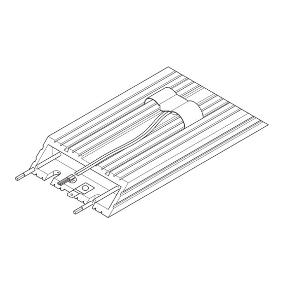
    Description du produit Présentation générale Description du produit Présentation générale ERBMXXX010 Équipement livré Pos. Description Résistance de freinage Instructions de montage Eléments de la résistance de freinage Pos. Description Plaque signalétique Contact thermique Câble de raccordement pour le contact thermique Câble de raccordement pour la résistance de freinage Raccordement PE Consignes préventives...
  • Page 47: Utilisation Conforme À La Fonction

    Description du produit Utilisation conforme à la fonction Utilisation conforme à la fonction Les résistances de freinage ƒ ne doivent être utilisées qu’aux fins décrites dans les présentes instructions de montage. ƒ sont des composants destinés – à être intégrés dans une machine. –...
  • Page 48: Conditions De Référence

    Description du produit Conditions de référence Conditions de référence En cas d’utilisation de résistances de freinage, tenir compte des points suivants : ƒ Puissance génératrice moyenne < puissance permanente P de la résistance de freinage ƒ Puissance génératrice pendant le temps de freinage <...
  • Page 49 Description du produit Conditions de référence Exemples d’évaluation de la condition de référence Données de base : cycle de la résistance de freinage t = 150 s cyc,RB et temps de freinage max. t = 10 s. Les temps de freinage brk,max et le cycle du process t sont fournis à...
  • Page 50: Spécifications Techniques

    Spécifications techniques Caractéristiques générales et conditions d’utilisation Spécifications techniques Caractéristiques générales et conditions d’utilisation Conformité et homologation 2014/35/U Directive Basse Tension Homologation UL508 Industrial Control Equipment, Underwriter Laboratories (File−No. E232497) for USA and Canada Protection des personnes et protection de l’appareil Indice de IP50 protection...
  • Page 51: Caractéristiques Assignées

    Spécifications techniques Caractéristiques assignées Conditions de montage Emplacement de Dans l’armoire électrique montage L’emplacement de montage doit correspondre aux caractéristiques indiquées au chapitre Caractéristiques générales. Des objets ou des matériaux combustibles ne doivent pas se trouver à proximité de la résistance de freinage.
  • Page 52: Caractéristiques Mécaniques

    Spécifications techniques Caractéristiques mécaniques Caractéristiques mécaniques ERBMXXX007 [mm] ERBM047R135W ERBM090R086W ERBM100R086W 19.3 41.5 ERBM220R086W ERBM470R125W [mm] [kg] ERBM047R135W ERBM090R086W ± ERBM100R086W 0.32 ERBM220R086W ERBM470R125W ± EDKRBM470R DE/EN/FR 6.0...
  • Page 53: Installation Mécanique

    Installation mécanique Opérations de montage Installation mécanique Opérations de montage Ordre des opérations de montage de la résistance de freinage : 1. Sélectionner l’emplacement de montage adéquat. – Sélectionner l’emplacement de montage de façon à ce que les conditions d’utilisation (voir Spécifications techniques) soient garanties à...
  • Page 54: Installation Électrique

    Installation électrique Remarques importantes Installation électrique Remarques importantes Stop ! Risque de surchauffe de la résistance de freinage pendant le fonctionnement Une dissipation calorifique insuffisante pendant le fonctionnement risque de provoquer une surchauffe de la résistance de freinage. Risques encourus : Dommages irréversibles de la résistance de ƒ...
  • Page 55: Opérations De Montage

    Installation électrique Opérations de montage Variante 2 : avec rallongement des câbles ERBMXXX014 Connexion HF (collier de blindage) via connexion avec PE par surface importante Câbles torsadés Opérations de montage ERBMXXX013 Ordre des opérations de raccordement de la résistance de freinage 1.
  • Page 56: Maintenance

    Maintenance Intervalles de maintenance Maintenance Intervalles de maintenance La résistance ne nécessite aucun entretien. Cependant, il convient de procéder à des contrôles visuels réguliers. Selon les conditions ambiantes, prévoir des intervalles de contrôle suffisamment courts. Vérifier ƒ si les conditions ambiantes de la résistance de freinage correspondent toujours à...
  • Page 57 Maintenance EDKRBM470R DE/EN/FR 6.0...
  • Page 60 © 01/2019 Lenze Drives GmbH Service Lenze Service GmbH Postfach 10 13 52, 31763 Breslauer Straße 3, D−32699 Hameln Extertal Breslauer Straße 3, 32699 Extertal Germany GERMANY HR Lemgo B 6478 008000 2446877 +49 5154 82−0 (24 h helpline) Ê...

Table des Matières