Table des Matières

Publicité

Les langues disponibles

Les langues disponibles

Liens rapides

EDKRBD180R
.ZCm
L−force Drives
Montageanleitung
Mounting Instructions
Instructions de montage
ERB
ERBDxxxRxxxx
Bremswiderstand
Brake resistor
Résistance de freinage
l

Publicité

Table des Matières
loading

Sommaire des Matières pour Lenze ERBD R Série

  • Page 1 L−force Drives EDKRBD180R .ZCm Montageanleitung Mounting Instructions Instructions de montage ERBDxxxRxxxx Bremswiderstand Brake resistor Résistance de freinage...
  • Page 2 Lesen Sie zuerst diese Anleitung und die Dokumentation zum Grundgerät, bevor Sie mit den Arbeiten beginnen! Beachten Sie die enthaltenen Sicherheitshinweise. Please read these instructions and the documentation of the standard device before you start working! Observe the safety instructions given therein! Lire le présent fascicule et la documentation relative à...
  • Page 3: Table Des Matières

    Inhalt Über diese Dokumentation ......... Informationen zur Gültigkeit .
  • Page 4: Über Diese Dokumentation

    Qualifiziertes Fachpersonal sind Personen, die für die auszuführenden Tätigkei- ten bei der Aufstellung, Montage, Inbetriebsetzung und dem Betrieb des Pro- dukts über entsprechende Qualifikationen verfügen. Tipp! Informationen und Hilfsmittel rund um die Lenze−Produkte finden Sie im Download−Bereich unter www.lenze.com EDKRBD180R DE/EN/FR 9.0...
  • Page 5: Dokumenthistorie

    Über diese Dokumentation Dokumenthistorie Dokumenthistorie Materialnummer Version Beschreibung .ZCm 05/2019 TD15 Überarbeitung 13440637 07/2013 TD29 Überarbeitung 13367514 02/2011 TD29 Überarbeitung Verwendete Konventionen Informationsart Auszeichnung Beispiele/Hinweise Zahlenschreibweise Dezimaltrennzeichen Punkt Es wird generell der Dezimalpunkt verwendet. Zum Beispiel: 1234.56 Warnhinweise UL−Warnhinweise Werden in englischer und französi- scher Sprache verwendet.
  • Page 6: Verwendete Hinweise

    Über diese Dokumentation Verwendete Hinweise Verwendete Hinweise Um auf Gefahren und wichtige Informationen hinzuweisen, werden in dieser Dokumentation folgende Piktogramme und Signalwörter verwendet: Sicherheitshinweise Aufbau der Sicherheitshinweise: Gefahr! (kennzeichnet die Art und die Schwere der Gefahr) Hinweistext (beschreibt die Gefahr und gibt Hinweise, wie sie vermieden werden kann) Piktogramm und Signalwort Bedeutung...
  • Page 7 Über diese Dokumentation Verwendete Hinweise Spezielle Sicherheitshinweise und Anwendungshinweise für UL und UR Piktogramm und Signalwort Bedeutung Sicherheitshinweis oder Anwendungshinweis für den Betrieb eines UL−approbierten Geräts in UL−approbier- ten Anlagen. Warnings! Möglicherweise wird das Antriebssystem nicht UL−ge- recht betrieben, wenn nicht die entsprechenden Maß- nahmen getroffen werden.
  • Page 8: Sicherheitshinweise

    Schaltungsausschnitte sind Vorschläge, deren Übertragbarkeit auf die jeweilige Anwendung überprüft werden muss. Für die Eignung der angege- benen Verfahren und Schaltungsvorschläge übernimmt der Hersteller keine Gewähr. Alle Arbeiten mit und an Lenze−Antriebs− und ƒ Automatisierungskomponenten darf nur qualifiziertes Fachpersonal ausführen.
  • Page 9: Restgefahren

    Sicherheitshinweise Restgefahren Restgefahren Gefahr! Gefährliche elektrische Spannung Während des Betriebs des Grundgeräts und bis zu 3 Minuten nach dem Netzabschalten können an den Anschlüssen des Bremswiderstands gefährliche elektrische Spannungen anliegen. Mögliche Folgen: Tod oder schwere Verletzungen beim Berühren der ƒ Anschlussklemmen.
  • Page 10 Sicherheitshinweise Restgefahren Stop! Mögliche Überhitzung des Bremswiderstands während des Betriebs Durch ungenügende Wärmeabfuhr kann der Bremswiderstand während des Betriebs überhitzen. Mögliche Folgen: Der Bremswiderstand wird zerstört. ƒ Der Antrieb wird nicht abgebremst sondern trudelt aus. ƒ Schutzmaßnahmen: Den Thermokontakt des Bremswiderstands immer anschließen. ƒ...
  • Page 11 The nominal loads of the resistors refer to conditions where the ƒ surrounding temperature does not exceed 40 °C. If the temperature exceeds 40 °C, contact LENZE for advice regarding de−rating of nominal power. The surface temperature must not exceed 355 °C at any point of ƒ...
  • Page 12: Produktbeschreibung

    Produktbeschreibung Übersicht Produktbeschreibung Übersicht ERBDECS001 Lieferumfang Pos. Beschreibung Bremswiderstand Montageanleitung Elemente am Bremswiderstand Pos. Beschreibung Klemmenkasten Kabelverschraubung Bremswiderstand−Leitung Kabelverschraubung Thermokontakt−Leitung Befestigungswinkel Warnhinweis Typenschild EDKRBD180R DE/EN/FR 9.0...
  • Page 13: Identifikation

    Produktbeschreibung Identifikation Identifikation ERBDECS002  Typenschlüssel ERBx xxxx xxxx Produktreihe Widerstand R 470R = 470 W z. B. 075D = 7.5 W Dauerleistung P z. B. 120W = 120 W 01K2 = 1.2 kW EDKRBD180R DE/EN/FR 9.0...
  • Page 14: Bestimmungsgemäße Verwendung

    Produktbeschreibung Bestimmungsgemäße Verwendung Bestimmungsgemäße Verwendung Bremswiderstände nur unter den in dieser Betriebsanleitung vorgeschriebenen ƒ Einsatzbedingungen betreiben. sind Komponenten ƒ – zum Einbau in eine Maschine. – zum Zusammenbau mit anderen Komponenten zu einer Maschine. Die Inbetriebnahme des Bremswiderstands ist solange untersagt, bis fest- gestellt wurde, dass die Maschine, in welche der Bremswiderstand einge- baut werden soll, den Bestimmungen der EG−Maschinenrichtlinie ent- sprechen.
  • Page 15: Auslegungsbedingungen

    Produktbeschreibung Auslegungsbedingungen Auslegungsbedingungen Beim Einsatz von Bremswiderständen beachten: Mittelwert der generatorischen Leistung < Dauerleistung P ƒ Bremswiderstands. Generatorische Leistung während der Bremszeit < Wärmemenge Q ƒ Bremswiderstands. Bremszeit < 10 % der Zykluszeit (Bremszeit + Pausenzeit). ƒ Thermokontakt immer anschließen und so in die Anlagenüberwachung ƒ...
  • Page 16 Produktbeschreibung Auslegungsbedingungen Beispiele für die Auswertung der Bedingung Gegeben ist der Bremswiderstandzyklus t = 150 s und die max. Brems- cyc,RB dauer t = 10 s. Die Bremszeiten t und der Prozesszyklus t sind bei- brk,max cyc,Prc spielhaft. Im oberen Beispiel wird die Auslegungsbedingung zu jedem Zeitpunkt einge- halten.
  • Page 17: Technische Daten

    Technische Daten Allgemeine Daten und Einsatzbedingungen Technische Daten Allgemeine Daten und Einsatzbedingungen Konformität und Approbation 2014/35/EU Niederspannungsrichtlinie Approbation UL508 Industrial Control Equipment, Underwriter Laborato- ries (File−No. E208678) for USA and Canada Personenschutz und Geräteschutz Schutzart EN 60529 IP20 NEMA 250 Berührschutz nach Typ 1 Thermokontakt...
  • Page 18 Technische Daten Allgemeine Daten und Einsatzbedingungen Montagebedingungen Montageort Der Montageort muss den in den "Allgemeinen Daten" genannten Geräteeigenschaften ent- sprechen. Brennbare Materialien oder Stoffe dürfen sich nicht in der Nähe des Bremswiderstands befin- den. Die vom Bremswiderstand erzeugte Wärme muss ungehindert abgeführt werden.
  • Page 19: Bemessungsdaten

    Technische Daten Bemessungsdaten Bemessungsdaten Elektrische Daten [kWs] ERBD015R04K0 4000 ERBD018R01K6 1600 ERBD018R03K0 3000 ERBD018R06K0 6000 ERBD022R03K0 3000 ERBD033R02K0 2000 ERBD047R01K2 1200 ERBD068R800W ERBD082R600W ERBD100R600W ERBD180R300W Widerstand Dauerleistung Wärmemenge Max. Betriebsspannung Temperaturen [°C] Innen 1000 Am Gehäuse An der Einbauf- reiraumgrenze Maximale Temperatur bei Bemessungsdaten Temperatur bei der der Thermokontakt auslöst Maximale Temperatur bei sachwidriger Verwendung...
  • Page 20: Mechanische Daten

    Technische Daten Mechanische Daten Mechanische Daten Bauform 1 ERBDECS003 [mm] [kg] ERBD180R300W ±2 141 6.5 200 100 ERBD100R600W ±2 ERBD082R600W EDKRBD180R DE/EN/FR 9.0...
  • Page 21 Technische Daten Mechanische Daten Bauform 2 ERBDECS004 [mm] [kg] ERBD068R800W ± ERBD047R01K2 ± ERBD018R01K6 EDKRBD180R DE/EN/FR 9.0...
  • Page 22 Technische Daten Mechanische Daten Bauform 3 ERBDECS005 [mm] [kg] ERBD033R02K0 ± EDKRBD180R DE/EN/FR 9.0...
  • Page 23 Technische Daten Mechanische Daten Bauform 4 ERBDECS006 [mm] [kg] ERBD018R03K0 11.3 ± ERBD022R03K0 EDKRBD180R DE/EN/FR 9.0...
  • Page 24 Technische Daten Mechanische Daten Bauform 5 ERBDECS007 [mm] [kg] ERBD015R04K0 14.3 ± EDKRBD180R DE/EN/FR 9.0...
  • Page 25 Technische Daten Mechanische Daten Bauform 6 ERBDECS008 [mm] [kg] ERBD018R06K0 18.0 ± EDKRBD180R DE/EN/FR 9.0...
  • Page 26: Mechanische Installation

    Mechanische Installation Montageschritte Mechanische Installation Montageschritte So montieren Sie den Bremswiderstand: 1. Wählen Sie einen geeigneten Montageort. – Der Montageort muss die in den Technischen Daten genannten Einsatzbedingungen immer gewährleisten; ggf. zusätzliche Maßnahmen ergreifen. – Eine ungehinderte Luftzirkulation zum Abführen der Wärme muss gewährleistet sein.
  • Page 27: Elektrische Installation

    Elektrische Installation Wichtige Hinweise Elektrische Installation Wichtige Hinweise Stop! Mögliche Überhitzung des Bremswiderstands während des Betriebs Durch ungenügende Wärmeabfuhr kann der Bremswiderstand während des Betriebs überhitzen. Mögliche Folgen: Der Bremswiderstand wird zerstört. ƒ Der Antrieb wird nicht abgebremst sondern trudelt aus. ƒ...
  • Page 28: Anschlussplan

    Elektrische Installation Anschlussplan Anschlussplan Variante 1 (kurze Leitungen) RB1 RB2 T1 T2 ERBG008 Verdrillte Leitungen Variante 2 (lange Leitungen) RB1 RB2 T1 T2 " " ERBG007 " HF−Schirmabschluss durch großflächige PE−Anbindung Verdrillte Leitungen EDKRBD180R DE/EN/FR 9.0...
  • Page 29: Montageschritte

    Elektrische Installation Montageschritte Montageschritte ERBDECS010 So schließen Sie den Bremswiderstand an: 1. Grundgerät vom Netz trennen und alle Leistungsklemmen auf Spannungsfreiheit prüfen. 2. Klemmenabdeckung demontieren. 3. Bremswiderstand−Leitung auflegen: – Bei einer Leitungslänge bis 0.5 m verdrillte Leitung verwenden (Anschlussplan Variante 1). –...
  • Page 30: Wartung

    Wartung Wartungsintervalle Wartung Wartungsintervalle Der Bremswiderstand ist wartungsfrei. Trotzdem müssen Sie in regelmäßigen und unter Berücksichtigung der Umgebungsbedingungen ausreichend kurzen Intervallen eine Sichtprüfung durchführen. Kontrollieren Sie: Entspricht die Umgebung des Bremswiderstands noch den in den ƒ Technischen Daten genannten Einsatzbedingungen? Behindert kein Staub oder Schmutz die Wärmeabfuhr des ƒ...
  • Page 31 Contents About this documentation ......... Validity information .
  • Page 32: About This Documentation

    Qualified skilled personnel are persons who have the required qualifications to carry out all activities involved in installing, mounting, commissioning, and operating the product. Tip! Information and tools concerning the Lenze products can be found in the download area at www.lenze.com Document history...
  • Page 33: Conventions Used

    About this documentation Conventions used Conventions used Type of information Identification Examples/notes Spelling of numbers Decimal separator Point In general, the decimal point is used. For instance: 1234.56 Warnings UL warnings Given in English and French UR warnings Text Program name »...
  • Page 34: Notes Used

    About this documentation Notes used Notes used The following pictographs and signal words are used in this documentation to indicate dangers and important information: Safety instructions Structure of safety instructions: Danger! (characterises the type and severity of danger) Note (describes the danger and gives information about how to prevent dangerous situations) Pictograph and signal word Meaning...
  • Page 35 About this documentation Notes used Special safety instructions and application notes for UL and UR Pictograph and signal word Meaning Safety or application note for the operation of a UL−approved device in UL−approved systems. Warnings! Possibly the drive system is not operated in compliance with UL if the corresponding measures are not taken.
  • Page 36: Safety Instructions

    The manufacturer does not accept any liability for the suitability of the specified procedures and circuit proposals. Only qualified skilled personnel are permitted to work with or on Lenze ƒ drive and automation components.
  • Page 37: Residual Hazards

    Safety instructions Residual hazards Residual hazards Danger! Dangerous electrical voltage The terminals of the brake resistor may carry dangerous voltages during operation of the basic device and up to three minutes after mains disconnection. Possible consequences: Death or severe injuries when touching the terminals. ƒ...
  • Page 38 Safety instructions Residual hazards Stop! Possible overheating of the brake resistor during operation Inadequate heat dissipation during operation can cause the brake resistor to overheat. Possible consequences: The brake resistor is destroyed. ƒ The drive is not braked but coasts to a standstill. ƒ...
  • Page 39 The nominal loads of the resistors refer to conditions where the ƒ surrounding temperature does not exceed 40 °C. If the temperature exceeds 40 °C, contact LENZE for advice regarding de−rating of nominal power. The surface temperature must not exceed 355 °C at any point of ƒ...
  • Page 40: Product Description

    Product description Overview Product description Overview ERBDECS001 Scope of supply Pos. Description Brake resistor Mounting Instructions Brake resistor elements Pos. Description Terminal box Cable gland for brake resistor cable Cable gland for thermal contact cable Fixing bracket Warning note Nameplate EDKRBD180R DE/EN/FR 9.0...
  • Page 41: Identification

    Product description Identification Identification ERBDECS002  Type code ERBx xxxx xxxx Product series Resistance R 470R = 470 W e.g. 075D = 7.5 W Permanent power P e.g. 120W = 120 W 01k2 = 1.2 kW EDKRBD180R DE/EN/FR 9.0...
  • Page 42: Application As Directed

    Product description Application as directed Application as directed Brake resistors must only be actuated under the operating conditions specified in these ƒ operating instructions. are components ƒ – for mounting in a machine. – for assembly with other components to a machine. Commissioning of the brake resistor is prohibited until it has been determined that the machine into which the brake resistor is to be mounted complies with the regulations of the EC Machinery Directive.
  • Page 43: Dimensioning Conditions

    Product description Dimensioning conditions Dimensioning conditions If brake resistors are used, observe the following: Mean value of regenerative power < permanent power P of the brake ƒ resistor. Regenerative power during braking time < heat quantity Q of the brake ƒ...
  • Page 44 Product description Dimensioning conditions Examples of the evaluation of the condition The brake resistor cycle t = 150 s and the max. total braking time t cyc,RB brk,max = 10 s are given. The braking times t and the process cycle t cyc,Prc exemplary.
  • Page 45: Technical Data

    Technical data General data and operating conditions Technical data General data and operating conditions Conformity and approval 2014/35/EU Low−Voltage Directive Approval UL508 Industrial Control Equipment, Underwriter Laboratories (File−No. E208678) for USA and Canada Protection of persons and equipment Enclosure EN 60529 IP20 NEMA 250 Protection against...
  • Page 46 Technical data General data and operating conditions Mounting conditions Mounting location The mounting location must comply with the device features mentioned in the chapter "General data". Flammable materials or substances may not be placed in the vicinity of the brake resistor. The heat generated by the brake resistor must be dissipated freely.
  • Page 47: Rated Data

    Technical data Rated data Rated data Electrical data [kWs] ERBD015R04K0 4000 ERBD018R01K6 1600 ERBD018R03K0 3000 ERBD018R06K0 6000 ERBD022R03K0 3000 ERBD033R02K0 2000 ERBD047R01K2 1200 ERBD068R800W ERBD082R600W ERBD100R600W ERBD180R300W Resistance Permanent power Heat quantity Max. operating voltage Temperatures [°C] Inside 1000 At the housing On the clearance edge Maximum temperature for rated data...
  • Page 48: Mechanical Data

    Technical data Mechanical data Mechanical data Design 1 ERBDECS003 [mm] [kg] ERBD180R300W ±2 141 6.5 200 100 ERBD100R600W ±2 ERBD082R600W EDKRBD180R DE/EN/FR 9.0...
  • Page 49 Technical data Mechanical data Design 2 ERBDECS004 [mm] [kg] ERBD068R800W ± ERBD047R01K2 ± ERBD018R01K6 EDKRBD180R DE/EN/FR 9.0...
  • Page 50 Technical data Mechanical data Design 3 ERBDECS005 [mm] [kg] ERBD033R02K0 ± EDKRBD180R DE/EN/FR 9.0...
  • Page 51 Technical data Mechanical data Design 4 ERBDECS006 [mm] [kg] ERBD018R03K0 11.3 ± ERBD022R03K0 EDKRBD180R DE/EN/FR 9.0...
  • Page 52 Technical data Mechanical data Design 5 ERBDECS007 [mm] [kg] ERBD015R04K0 14.3 ± EDKRBD180R DE/EN/FR 9.0...
  • Page 53 Technical data Mechanical data Design 6 ERBDECS008 [mm] [kg] ERBD018R06K0 18.0 ± EDKRBD180R DE/EN/FR 9.0...
  • Page 54: Mechanical Installation

    Mechanical installation Mounting steps Mechanical installation Mounting steps How to mount the brake resistor: 1. Select a suitable mounting location. – The mounting location must always ensure the operating conditions mentioned in the technical data; if required, additional measures must be taken.
  • Page 55: Electrical Installation

    Electrical installation Important notes Electrical installation Important notes Stop! Possible overheating of the brake resistor during operation Inadequate heat dissipation during operation can cause the brake resistor to overheat. Possible consequences: The brake resistor is destroyed. ƒ The drive is not braked but coasts to a standstill. ƒ...
  • Page 56: Connection Plan

    Electrical installation Connection plan Connection plan Version 1 (short cables) RB1 RB2 T1 T2 ERBG008 Twisted cables Version 2 (long cables) RB1 RB2 T1 T2 " " ERBG007 " HF−shield termination by extensive PE connection Twisted cables EDKRBD180R DE/EN/FR 9.0...
  • Page 57: Mounting Steps

    Electrical installation Mounting steps Mounting steps ERBDECS010 How to connect the brake resistor: 1. Disconnect the basic device from the mains and check that no voltage is applied to the power terminals. 2. Remove the terminal cover. 3. Connect the brake resistor cable: –...
  • Page 58: Maintenance

    Maintenance Maintenance intervals Maintenance Maintenance intervals The brake resistor is maintenance−free. Nevertheless, a visual inspection must be executed in short and regular intervals considering the ambient conditions. Ensure that: the environment of the brake resistor still corresponds to the operating ƒ...
  • Page 59 Sommaire Présentation du document ......... Validité...
  • Page 60: Présentation Du Document

    à leurs activités. Conseil ! Toutes les informations relatives aux produits Lenze peuvent être téléchargées sur notre site à l’adresse suivante : www.Lenze.com Historique du document Numéro de matériel...
  • Page 61: Conventions Utilisées

    Présentation du document Conventions utilisées Conventions utilisées Type d’information Aperçu Exemples/remarques Représentation des chiffres Séparateur décimal Point Le point décimal est généralement utilisé. Exemple : 1234.56 Consignes préventives Consignes préventives UL En anglais et en français Consignes préventives UR Mise en évidence de textes spéciaux Nom de programme »...
  • Page 62: Consignes Utilisées

    Présentation du document Consignes utilisées Consignes utilisées Pour indiquer des risques et des informations importantes, la présente documentation utilise les mots et pictogrammes suivants : Consignes de sécurité Présentation des consignes de sécurité Danger ! (Le pictogramme indique le type de risque.) Explication (L’explication décrit le risque et les moyens de l’éviter.) Pictogramme et mot associé...
  • Page 63: Avertissements

    Présentation du document Consignes utilisées Consignes de sécurité et d’utilisation spécifiques selon UL et UR Pictogramme et mot associé Explication Consigne de sécurité ou d’utilisation pour le fonctionnement d’un appareil homologué UL dans des installations homologuées UL Avertissements ! Le système d’entraînement risque de ne pas être utilisé selon les directives UL si des mesures correspondantes ne sont pas prévues.
  • Page 64: Consignes De Sécurité

    Les procédures à suivre et les plans de raccordement fournis constituent des recommandations dont l’adéquation avec l’application concernée doit être vérifiée. Lenze n’assumera aucune responsabilité pour les dommages liés à un problème d’adéquation des procédures et plans de raccordements indiqués.
  • Page 65: Dangers Résiduels

    Consignes de sécurité Dangers résiduels Dangers résiduels Danger ! Tension électrique dangereuse Les raccords de la résistance de freinage sont sous tension pendant le fonctionnement de l’appareil de base et jusqu’à 3 minutes après la coupure réseau. Risques encourus Mort ou blessures très graves en cas de contact accidentel avec ƒ...
  • Page 66 Consignes de sécurité Dangers résiduels Stop ! Risque de surchauffe de la résistance de freinage pendant le fonctionnement Une dissipation calorifique insuffisante pendant le fonctionnement risque de provoquer une surchauffe de la résistance de freinage. Risques encourus : Dommages irréversibles de la résistance de freinage ƒ...
  • Page 67 Les charges nominales des résistances s’entendent pour un ƒ environnement caractérisé par une température ambiante maximale de 40° C. Au−delà de 40° C, contacter LENZE pour obtenir des recommandations relatives au déclassement de la puissance nominale. La température de surface ne doit dépasser 355° C en aucun ƒ...
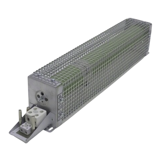
  • Page 68: Description Du Produit

    Description du produit Présentation générale Description du produit Présentation générale ERBDECS001 Équipement livré Pos. Description Résistance de freinage Instructions de montage Eléments de la résistance de freinage Pos. Description Boîte à bornes Presse−étoupe du câble de la résistance de freinage Presse−étoupe du câble du contact thermique Equerres de fixation Consignes préventives...
  • Page 69: Identification

    Description du produit Identification Identification ERBDECS002  Codification des types ERBx xxxx xxxx Série d’appareils Résistance R 470R = 470 W Exem 075D = 7.5 W Puissance permanente Exem 120W = 120 W 01k2 = 1.2 kW EDKRBD180R DE/EN/FR 9.0...
  • Page 70: Utilisation Conforme À La Fonction

    Description du produit Utilisation conforme à la fonction Utilisation conforme à la fonction Les résistances de freinage ne doivent être utilisées qu’aux fins décrites dans les présentes ƒ instructions de montage. sont des composants destinés ƒ – à être intégrés dans une machine. –...
  • Page 71: Conditions De Référence

    Description du produit Conditions de référence Conditions de référence En cas d’utilisation de résistances de freinage, tenir compte des points suivants Puissance génératrice moyenne < puissance permanente P de la ƒ résistance de freinage Puissance génératrice pendant le temps de freinage < puissance ƒ...
  • Page 72 Description du produit Conditions de référence Exemples d’évaluation de la condition de référence Données de base : cycle de la résistance de freinage t = 150 s et temps de cyc,RB freinage max. t = 10 s. Les temps de freinage t et le cycle du process brk,max sont fournis à...
  • Page 73: Spécifications Techniques

    Spécifications techniques Caractéristiques générales et conditions d’utilisation Spécifications techniques Caractéristiques générales et conditions d’utilisation Conformité et homologation 2014/35/UE Directive Basse Tension Homologation UL508 Industrial Control Equipment, Underwriter Laboratories (File−No. E208678) for USA and Canada Protection des personnes et protection de l’appareil Indice de protection EN 60529 IP20...
  • Page 74 Spécifications techniques Caractéristiques générales et conditions d’utilisation Conditions de montage Emplacement de L’emplacement de montage doit correspondre montage aux caractéristiques indiquées au chapitre Caractéristiques générales. Des objets ou des matériaux combustibles ne doivent pas se trouver à proximité de la résistance de freinage.
  • Page 75: Caractéristiques Assignées

    Spécifications techniques Caractéristiques assignées Caractéristiques assignées Caractéristiques électriques [kWs] ERBD015R04K0 4000 ERBD018R01K6 1600 ERBD018R03K0 3000 ERBD018R06K0 6000 ERBD022R03K0 3000 ERBD033R02K0 2000 ERBD047R01K2 1200 ERBD068R800W ERBD082R600W ERBD100R600W ERBD180R300W Résistance Puissance permanente Puissance calorifique Tension de fonctionnement maxi Températures [°C] A I’ntérieur 1000 Sur le coffret au niveau de la...
  • Page 76: Caractéristiques Mécaniques

    Spécifications techniques Caractéristiques mécaniques Caractéristiques mécaniques Forme de construction 1 ERBDECS003 [mm] [kg] ERBD180R300W ±2 141 6.5 200 100 ERBD100R600W ±2 ERBD082R600W EDKRBD180R DE/EN/FR 9.0...
  • Page 77 Spécifications techniques Caractéristiques mécaniques Forme de construction 2 ERBDECS004 [mm] [kg] ERBD068R800W ± ERBD047R01K2 ± ERBD018R01K6 EDKRBD180R DE/EN/FR 9.0...
  • Page 78 Spécifications techniques Caractéristiques mécaniques Forme de construction 3 ERBDECS005 [mm] [kg] ERBD033R02K0 ± EDKRBD180R DE/EN/FR 9.0...
  • Page 79 Spécifications techniques Caractéristiques mécaniques Forme de construction 4 ERBDECS006 [mm] [kg] ERBD018R03K0 11.3 ± ERBD022R03K0 EDKRBD180R DE/EN/FR 9.0...
  • Page 80 Spécifications techniques Caractéristiques mécaniques Forme de construction 5 ERBDECS007 [mm] [kg] ERBD015R04K0 14.3 ± EDKRBD180R DE/EN/FR 9.0...
  • Page 81 Spécifications techniques Caractéristiques mécaniques Forme de construction 6 ERBDECS008 [mm] [kg] ERBD018R06K0 18.0 ± EDKRBD180R DE/EN/FR 9.0...
  • Page 82: Installation Mécanique

    Installation mécanique Opérations de montage Installation mécanique Opérations de montage Ordre des opérations de montage de la résistance de freinage : 1. Sélectionner l’emplacement de montage adéquat. – Sélectionner l’emplacement de montage de façon à ce que les conditions d’utilisation (voir Spécifications techniques) soient garanties à...
  • Page 83: Installation Électrique

    Installation électrique Remarques importantes Installation électrique Remarques importantes Stop ! Risque de surchauffe de la résistance de freinage pendant le fonctionnement Une dissipation calorifique insuffisante pendant le fonctionnement risque de provoquer une surchauffe de la résistance de freinage. Risques encourus : Dommages irréversibles de la résistance de freinage ƒ...
  • Page 84: Schéma De Câblage

    Installation électrique Schéma de câblage Schéma de câblage Variante 1 (câbles courts) RB1 RB2 T1 T2 ERBG008 Câbles torsadés Variante 2 (câbles longs) RB1 RB2 T1 T2 " " ERBG007 " Connexion HF (collier de blindage) via connexion avec PE par surface importante Câbles torsadés EDKRBD180R DE/EN/FR 9.0...
  • Page 85: Opérations De Montage

    Installation électrique Opérations de montage Opérations de montage ERBDECS010 Ordre des opérations de raccordement de la résistance de freinage 1. Couper l’appareil de base du réseau et vérifier si toutes les bornes de puissance sont hors tension. 2. Démonter le cache−bornier. 3.
  • Page 86: Maintenance

    Maintenance Intervalles de maintenance Maintenance Intervalles de maintenance La résistance ne nécessite aucun entretien. Cependant, il convient de procéder à des contrôles visuels réguliers. Selon les conditions ambiantes, prévoir des intervalles de contrôle suffisamment courts. Vérifier si les conditions ambiantes de la résistance de freinage correspondent ƒ...
  • Page 88 © 05/2019 Lenze Drives GmbH Service Lenze Service GmbH Postfach 10 13 52, 31763 Hameln Breslauer Straße 3, D−32699 Extertal Breslauer Straße 3, 32699 Extertal GERMANY Germany HR Lemgo B 6478 +49 5154 82−0 008000 2446877 (24 h helpline) Ê...

Table des Matières