Textron Ransomes MATADOR 71 Mode D'emploi
Les langues disponibles
Les langues disponibles
Liens rapides
Safety, Operation & Maintenance Manual
Manuel de sécurité, de fonctionnement et de maintenance
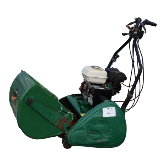
Ransomes MATADOR 71 - HONDA GX160-K1
Series / Série : EH4
Product Code / Code produit : LDDD704
AVERTISSEMENT
AVERTISSEMENT : Risque de blessures graves en
cas d'utilisation incorrecte de la machine. Les
opérateurs et le personnel d'entretien doivent ętre
formés et conscients des dangers encourus. Ils
doivent lire avec attention le manuel avant d'essayer
de monter, d'utiliser, de régler ou d'entretenir la
machine.
FR
RJL 100 September 2014
France
25067G-FR (rev. 1)
®

Manuels Connexes pour Textron Ransomes MATADOR 71


Sommaire des Matières pour Textron Ransomes MATADOR 71
- Page 1 25067G-FR (rev. 1) ® Safety, Operation & Maintenance Manual Manuel de sécurité, de fonctionnement et de maintenance Ransomes MATADOR 71 - HONDA GX160-K1 Series / Série : EH4 Product Code / Code produit : LDDD704 AVERTISSEMENT AVERTISSEMENT : Risque de blessures graves en cas d’utilisation incorrecte de la machine.
- Page 62 13 GUARANTEE NOTES en-62...
- Page 64 1 TABLE DES MATIÈRES SECTION ..................PÁGE SECTION ..................PÁGE INTRODUCTION RÉGLAGES ..............3 ....39 MPORTANT ÉTERMINATION DE LA HAUTEUR DE COUPE ........4 ......39 DENTIFICATION DU PRODUIT ÉGLAGE DE LA HAUTEUR DE COUPE ......40 IRECTIVES CONCERNANT L ÉLIMINATION LIGNEMENT DU ROULEAU AVANT ...........
- Page 65 INTRODUCTION 2 IMPORTANT __________________________________________________________ Le Ransomes MATADOR est une tondeuse à touret à moteur à essence pour conducteur marchant La chaîne de traction et l'unité de coupe sont à entraînement par chaîne. IMPORTANT : Exécutez les opérations de maintenance conformément aux instructions du présent manuel afin de garantir une qualité...
- Page 66 2 INTRODUCTION IDENTIFICATION DU PRODUIT_________________________________________ Charge maximale sur l’essieu avant en kg (pour les machines conduites sur la voie publique) West Road Ransomes Europark Ipswich IP3 9TT Poids total en charge en kg England Charge maximale sur l’essieu arrière en kg (pour les machines conduites sur la voie publique) Puissance en kW Date de fabrication...
- Page 67 INTRODUCTION 2 DIRECTIVES CONCERNANT L’ÉLIMINATION DES PRODUITS MIS AU REBUT ___ 2.3.1 PENDANT LA DURÉE DE VIE DE LA MACHINE ___________________________ Le liquide de refroidissement du moteur, l'huile et les filtres à huile usagés sont des matières dangereuses. Il convient de suivre les procédures recommandées afin de garantir la sûreté...
- Page 68 2 INTRODUCTION MANUEL DES PIÈCES _________________________________________________ Conformément à la norme ISO 14001, Ransomes Jacobsen Limited n'envoie plus de manuel des pièces en version papier avec chaque produit. Si vous désirez consulter une liste des pièces de cette tondeuse, quatre options s'offrent à vous : Site Internet –...
- Page 69 INTRODUCTION 2 MONTAGE ___________________________________________________________ La tondeuse est équipée d'un récipient à l'usine et nécessite l'assemblage avant l'opération. Certains outils seront nécessaires pour l'assemblage. Jetez le récipient selon les exigences de protection environnementales applicables. Retirez la tondeuse du conteneur. Les poignées se trouvent autour du châssis - Figure 1.
- Page 70 2 INTRODUCTION REMARQUES fr-8...
- Page 71 SÉCURITÉ 3 3.1 POUR UNE UTILISATION SŰRE __________________________________________ AVERTISSEMENT UTILISER L'ÉQUIPEMENT DE FAÇON INAPPROPRIÉE ET SANS FORMATION COMPORTE DES RISQUES. Apprenez ŕ situer et ŕ utiliser correctement les commandes. Les opérateurs inexpérimentés doivent ętre formés par un tiers qui sait correctement manier l'équipement avant d'utiliser la tondeuse. Utilisez uniquement les pičces, accessoires et équipements agréés par Jacobsen.
- Page 72 3 SÉCURITÉ 3.1.3 Utilisation Ne démarrez jamais le moteur dans un lieu fermé ou mal ventilé. Le monoxyde de carbone présent dans les fumées d'échappement peut atteindre des niveaux dangereux. Ne transportez jamais de passagers. Éloignez toutes les personnes et animaux de la tondeuse. Désenclenchez tous les mécanismes d'entrainement et positionnez le frein de stationnement sur ON avant de démarrer le moteur.
- Page 73 SÉCURITÉ 3 3.1.4 Structure ROPS La structure ROPS est un dispositif de sécurité. La structure ROPS doit ętre en position verticale et verrouillée. Veillez ŕ toujours porter la ceinture de sécurité lorsque vous utilisez la tondeuse. Assurez-vous que la ceinture de sécurité peut ętre détachée rapidement en cas d'urgence. Ne faites fonctionner la tondeuse qu'avec la structure ROPS en position repliée sur des surfaces planes et nivelées si nécessaire.
- Page 74 3 SÉCURITÉ Lorsque vous mettez la tondeuse sur une remorque ou la stationnez, fermez le robinet de carburant. Ne gardez pas le carburant ŕ proximité de flammes et ne vidangez pas le carburant dans un bâtiment. Débranchez la batterie avant de réparer la tondeuse. Débranchez toujours le câble négatif de la batterie avant le câble positif de la batterie.
- Page 75 SÉCURITÉ 3 3.1.8 Consignes de sécurité importantes Ce symbole sert ŕ vous signaler la présence de possibles dangers. DANGER : Indique une situation dangereuse qui, si elle n'est pas évitée, ENTRAÎNERA des blessures graves, voire mortelles. AVERTISSEMENT : Indique une situation dangereuse qui, si elle n'est pas évitée, POURRAIT ENTRAÎNER des blessures graves, voire mortelles.
- Page 76 3 SÉCURITÉ AVERTISSEMENT Proposition 65 de l’État de Californie Les gaz d’échappement du moteur, certains de ses composants et certains composants du véhicule contiennent ou émettent des substances chimiques reconnues par l’État de Californie comme pouvant provoquer des cancers, des anomalies congénitales ou autres problèmes liés à la reproduction. AVERTISSEMENT Afin d'éviter des blessures dues à...
- Page 77 SÉCURITÉ 3 AVERTISSEMENT Il convient de porter des protections auditives lorsque vous utilisez des machines dont le bruit au niveau des oreilles de l'opérateur dépasse 85 dB(A) Leq. AVERTISSEMENT Limites d'exposition aux vibrations Les limites d'exposition sont calculées comme une combinaison du niveau de vibrations (amplitude) de l'outil et du temps d'exposition quotidienne (Heure de démarrage).
- Page 78 3 SÉCURITÉ REMARQUES fr-16...
- Page 79 SPÉCIFICATION 4 SPÉCIFICATIONS DU MOTEUR _________________________________________ Moteur essence Honda 2,95kW (4 CV)/ 2700 tr/min, à soupapes en tête, cylindre Type unique, 4 temps, à refroidissement par air, cylindre incliné à 25°, arbre horizontal. Modèle GX160 K1-QX4 Régime maximal 2700 ± 50 tr/min (à vide) Vitesse de ralenti 1400 ±...
- Page 80 4 SPÉCIFICATION SPÉCIFICATIONS DE LA MACHINE ______________________________________ Construction du châssis : Acier embouti soudé Transmission Chaînes à galets à haut rendement Embrayage Embrayage de transmission. Embrayage de cylindre séparé. Embrayage de rouleau niveleur séparé. Rouleau avant : Un rouleau d'acier d'une seule pièce, sur roulements à billes. Rouleau niveleur : 2 pièces en fonte lisse avec différentiel à...
- Page 81 En référence aux : Normes sur les mains/bras : BS EN ISO 5349-1 (2001) BS EN ISO 5349-2 (2002) Accélérations maxi. à droite ou à gauche Ransomes Matador 71 en m/s² Séries EH4 Niveau d'accélération Valeur moyenne des axes X,...
- Page 82 4 SPÉCIFICATION NIVEAU SONORE ____________________________________________________ La machine a été soumise à des essais de pression sonore (Ouie de l'opérateur). La directive de sécurité des machines 2006/42/CE Directive 2003/10 / CE sur l'exposition des travailleurs aux risques dus aux agents physiques (bruit) Conformément à...
- Page 83 SPÉCIFICATION 4 SPÉCIFICATIONS DES UNITÉS DE COUPE _______________________________ Structure Cylindre à 5 couteaux tous soudés Longueur de touret 71 cm 28 po Nombre de lames Rouleau avant Une pièce en acier Hauteur de coupe avec tête fixe (lame standard) 3 - 13mm (1/8 - 1/2po.) Rouleau arrière 2 pièces en fonte avec différentiel à...
- Page 84 4 SPÉCIFICATION 4.11 CERTIFICATS DE CONFORMITÉ ________________________________________ Ransomes Jacobsen Limited West Road, Ransomes Europark, Ipswich, England, IP3 9TT LDDD704 Ransomes Matador 71 Pedestrian Reel Mower EH400301 - EH499999 Honda GX160 K1-QX4 2.95kW (4HP)/ 2700 RPM 71cm 2006/42/EC (Machinery Directive) 2004/108/EC (EMC)
- Page 85 SPÉCIFICATION 4 84 dB(A) ± 1.3 Leq (2006/42/EC) EN ISO 5395-2013 (Garden Equipment Safety) EN ISO 14982:2009 (EMC) EN ISO 3744:2010 (Sound Power) EN ISO 3746:2010 (Sound Pressure) EN 1032:2003+A1:2008 (Vibration W/B) EN ISO 20643:2008 (Vibration H/A) EN 1033:1996(Vibration H/A) BS ISO 2631-1:1997 (Vibration W/B) ANSI B71.4-2012 Ransomes Jacobsen Limited...
- Page 86 4 SPÉCIFICATION DECLARATION OF INCORPORATION ДЕКЛАРАЦИЯ ЗА ОБЕДИНЕНИЕ PROHLÁŠENÍ O ZA ENÍ SPOLEČ NOSTI INKORPORERINGSERKLÆRING INCORPORATIEVERKLARING KINNITUS ÜHENDAMISE KOHTA ASENNUSTODISTUS DECLARATION D’INCORPORATION EINBAUBESCHEINIGUNG ΔΗΛΩΣΗ ΜΗ ΣΥΜΜΟΡΦΩΣΗΣ BEÉPÍTÉSI NYILATKOZAT DICHIARAZIONE DI INCORPORAZIONE NOFORMĒ ŠANAS DEKLARĀCIJA PRIJUNGIMO DEKLARACIJA DIKJARAZZJONI TA’ INKORPORAZZJONI DEKLARACJA ZGODNOŚ CI DLA PODZESPO U DECLARAÇÃO DE INCORPORAÇÃO DECLARAŢ IE DE ÎNCORPORARE VYHLÁSENIE O ZABUDOVANÍ...
- Page 87 La quasi-macchina non deve essere messa in servizio finché la macchina finale in cui deve essere incorporata non è stata dichiarata conforme, nel caso, alle disposizioni della Direttiva LDAA500, LDAA510, LDCB600 & 2006/42/CE. LDCB610 Ransomes Matador 71 Daļēji pabeigtu iekārtu nedrīkst nodot ekspluatācijā, līdz galīgā iekārta, kurā tā ir jāiebūvē, ir deklarēta atbilstoši direktīvas Nr. 2006/42/EK noteikumiem. LDDD081, LDDD181, LBDD700, LDDD700, LDDD704 Dalinai u baigto mechanizmo negalima paleisti kol kiti mechanizmai, kurie dar bus prijungti, nebus patvirtinti kaip atitinkantys 2006/42/EC Direktyvos reikalavimus.
- Page 88 4 SPÉCIFICATION REMARQUES fr-26...
- Page 89 VIGNETTES 5 5.1 VIGNETTES DE SÉCURITÉ ______________________________________________ 009034890 009034910 009034920 009034900 009114240 009034970 009034910 Lire le manuel de l'opérateur. 009034890 Maintenir une distance de sécurité autour de la machine. 009034920 Ne pas toucher aux surfaces chaudes. 009034900 Ne pas ouvrir ou retirer les dispositifs de protection lorsque le moteur est en marche. 009114240 Essence sans plomb, alerte de sécurité.
- Page 90 VIGNETTES 5.2 VIGNETTES D'INFORMATION ___________________________________________ 4130883 Contrôle de présence de l'opérateur (CPO), embrayage de rouleau niveleur / frein de stationnement. fr-28...
- Page 91 COMMANDES 6 CONTRÔLE DE PRÉSENCE DE L'OPÉRATEUR (CPO) _________________ La commande CPO se trouve sur la poignée côté droit. Pour l'actionner, appuyez sur le bouton (B) et tirez sur le levier (A) pour enclencher l'entraînement. Pour désenclencher le CPO, relâchez le levier (A). Le bouton (B) retourne dans sa position, bloquant l'actionnement du levier (A).
- Page 92 COMMANDES COMMANDE D'ACCÉLÉRATION ____________________________________ Pour modifier la vitesse de coupe, utilisez le levier manuel (E]) Pour augmenter le régime du moteur, déplacez le levier manuel (E) vers le bas. Pour réduire le régime du moteur, ramenez le levier manuel (D) dans la position de bas régime.
- Page 93 COMMANDES 6 LEVIER DE L'EMBRAYAGE DU CYLINDRE ___________________________ Pour enclencher l'embrayage de cylindre, déplacez le levier (F) vers le bas. Pour désenclencher l'embrayage de cylindre, ramenez le levier manuel dans la position de démarrage. COUPE-CIRCUIT_________________________________________________ La commutateur d'allumage est situé à l'avant du moteur. Déplacez le commutateur (A) dans la position «...
- Page 94 COMMANDES REMARQUES fr-32...
- Page 95 UTILISATION 7 7.1 CONTRÔLE QUOTIDIEN ________________________________________________ ATTENTION Assurez-vous que le moteur et l'échappement sont froids. N'effectuez pas le contrôle lorsque le moteur est chaud. Enclenchez le frein de stationnement et assurez-vous que les cylindres de coupe sont arrêtés. Vérifiez l'unité complète. Assurez-vous que les pièces ne sont pas usées ou desserrées, qu'il ne manque pas de composants ou que les composants ne sont pas endommagés et que le carburant et l'huile ne fuient pas.
- Page 96 UTILISATION 7.2 SYSTÈME DE VERROUILLAGE DE SÉCURITÉ ET DE DÉTECTION DE LA PRÉSENCE DE L’OPÉRATEUR __________________________________________ Le système de détection de la présence de l'opérateur commande l'embrayage de transmission principal. Vous pouvez démarrer le moteur mais l'entraînement ne s'enclenchera pas tant que le système CPO n'est pas activé...
- Page 97 UTILISATION 7 7.3 PROCÉDURE D’UTILISATION ____________________________________________ ATTENTION Pour éviter des blessures, veillez à toujours porter des lunettes de protection, des chaussures ou des bottes de travail en cuir, un casque et une protection auditive. Ne démarrez pas le moteur alors que le système CPO est enclenché. Ne faites pas fonctionner la machine ou ses accessoires si des composants sont desserrés, endommagés ou manquants.
- Page 98 UTILISATION ATTENTION Désenclenchez tous les mécanismes d'entraînement, enclenchez le frein de stationnement et arrêtez le moteur. Avant de nettoyer, régler ou réparer cette machine. AVERTISSEMENT NE PAS UTILISER SUR DES PENTES SUPÉRIEURES À 18° Lorsque vous travaillez sur des pentes ou à proximité de descentes, ralentissez et soyez prudent. Lisez la section 3.7.
- Page 99 UTILISATION 7 7.4 UTILISATION DE LA MACHINE ___________________________________________ Lisez les consignes de sécurité. COMMENT DÉMARRER LE MOTEUR POUR LA PREMIÈRE FOIS • Retirez le bouchon de remplissage du carter d'huile et assurez-vous que la machine se trouve sur une surface plane. Vérifiez que le carter d'huile est rempli. Si nécessaire, remplissez-le jusqu'en haut du filetage de l'orifice de remplissage avec une huile moteur recommandée.
- Page 100 UTILISATION 7.8 COMMENT ÉLIMINER UNE OBSTRUCTION DES UNITÉS DE COUPE __________ ATTENTION Remarque importante : de l'énergie peut rester stockée dans le système, celle-ci pouvant entraîner la rotation du cylindre de coupe lors de l'élimination de l'obstruction. Par conséquent, veuillez garder vos mains, pieds et vêtements éloignés des unités de coupe en permanence.
- Page 101 RÉGLAGES 8 DÉTERMINATION DE LA HAUTEUR DE COUPE __________________________ La hauteur de coupe est déterminée par la position des rouleaux avant par rapport à la contre-lame. Pour déterminer la hauteur de coupe, réglez le rouleau avant. Utilisez la hauteur de la barre de coupe (A) pour déterminer avec précision la hauteur de coupe.
- Page 102 RÉGLAGES RÉGLAGE DU CYLINDRE PAR RAPPORT À LA CONTRE-LAME ____________ Le cylindre de coupe doit être réglé de façon à se mettre en prise correctement avec la contre-lame. Vérification : inclinez la machine en arrière, tenez une fine feuille de papier entre le bord de la lame et les couteaux spiraux puis faites tourner le cylindre de coupe à...
- Page 103 RÉGLAGES 8 EMBRAYAGE DU ROULEAU NIVELEUR ________________________________ Le levier d'embrayage du rouleau niveleur se trouve sur la poignée droite. Pour enclencher l'embrayage et arrêter l'entraînement, tirez sur le levier. Pour désenclencher l'embrayage et entraîner le rouleau niveleur, relâchez le levier. Réglage : Cable Bracket Desserrez le contre-écrou (A).
- Page 104 RÉGLAGES RACLEUR DE ROULEAU NIVELEUR Pour régler le racleur, desserrez les vis (A) à chaque extrémité du racleur. Ajustez la position du racleur et serrez les vis. RÉGLAGES DES CHAÎNES ___________________________________________ Pour accéder aux chaînes, retirez le capot du carter de chaîne.
- Page 105 RÉGLAGES 8 MEULAGE DU CYLINDRE DE COUPE __________________________________ Les bords tranchants des couteaux spiraux sont entretenus par la technique du « meulage ». Retirez le capot du carter de chaîne. Vérifiez que le cylindre de coupe est réglé par rapport à la contre-lame. Retirez la chaîne B et désenclenchez l'embrayage du cylindre.
- Page 106 RÉGLAGES REMARQUES fr-44...
- Page 107 ACCESSOIRES 9 9.1 SIÈGE CONDUCTEUR __________________________________________________ Un siège conducteur est disponible. Il est fixé par un attelage à une boule. Utilisez uniquement un siège de conducteur Ransomes Jacobsen (LMAA747) avec ces machines. INSTALLATION Placez le siège conducteur derrière la machine. Faites tourner la goupille de blocage en avant.
- Page 108 ACCESSOIRES REMARQUES fr-46...
- Page 109 10 MAINTENANCE TABLEAU DE MAINTENANCE ET DE GRAISSAGE Intervalles Article Section Premier mois ou 20 Remplacer l'huile moteur 11.3 heures Vérifier le niveau d'huile du moteur 11.1 Chaque jour (10 heures) Vérifier l'élément du filtre ŕ air 10.2 Vérifier le moteur pour retirer toutes saletés 10.1 Nettoyer l’élément du filtre ŕ...
- Page 110 10 MAINTENANCE Ces chiffres sont fournis uniquement à titre d'information. Si le nombre d'heures d'utilisation pendant une quelconque période calendaire est plus important que celui indiqué, utilisez les heures de travail comme programme de maintenance. 10.1 MOTEUR - CONTRÔLE QUOTIDIEN (TOUTES LES 8 HEURES DE FONCTIONNEMENT) ___________________________________________________ Assurez-vous que le moteur et les commandes sont propres, dépourvus de débris de tonte et de saletés.
- Page 111 10 MAINTENANCE 10.2 MOTEUR - CONTRÔLE HEBDOMADAIRE : (TOUTES LES 50 HEURES DE FONCTIONNEMENT) ___________________________________________________ Filtre à air (de type élément double) : Retirez l'écrou à ailettes et la protection du filtre à air. Retirez les éléments et démontez-les. Vérifiez soigneusement que les deux éléments ne sont pas endommagés.
- Page 112 10 MAINTENANCE 10.3 CAPOT DE L'EMBRAYAGE ET DE L'ARBRE INTERMÉDIAIRE ________________ Desserrez les vis (A) et ôtez le capot d'entraînement. Nettoyez l'embrayage principal et la surface de l'arbre intermédiaire. Une fois totalement propre, remettez le capot d'entraînement en place et serrez les vis (A). 10.4 FREIN DU ROULEAU NIVELEUR _________________________________________ Vérifiez l'état de la bande de frein et réglez-la, voir 8.11.
- Page 113 GRAISSAGE 11 Les lubrifiants recommandés sont mentionnés à la section 4,4. Ces chiffres sont fournis uniquement à titre d'information. Si le nombre d'heures d'utilisation pendant une quelconque période calendaire est plus important que celui indiqué, utilisez les heures de travail comme programme de graissage. 11.1 MOTEUR - CONTRÔLE QUOTIDIEN : (TOUTES LES 8 HEURES DE FONCTIONNEMENT) ________________________________________________...
- Page 114 11 GRAISSAGE 11.3 MOTEUR - CONTRÔLE HEBDOMADAIRE : (TOUTES LES 50 HEURES DE FONCTIONNEMENT) ________________________________________________ Procédez à la vidange et remplissez de nouveau le carter, voir 11.2 11.4 MACHINE _________________________________________________________ Avant d'utiliser la machine pour la première fois, graissez A, B et C. Utilisez la graisse recommandée. A Roulements du cylindre de coupe B Rouleau niveleur C Axe du rouleau avant...
- Page 115 QUALITÉ DE COUPE 12 QUALITÉ DE COUPE - RÉSOLUTION DE PROBLČMES ____________________ Effectuez un « test de coupe » pour évaluer les 1. Vitesse de tonte (au sol). performances de la tondeuse avant d'entreprendre 2. État du roulement du touret et réglage de la pré- des réparations.
- Page 116 12 QUALITÉ DE COUPE 12.2 ONDULATION MARCEL______________________________________________ L'ondulation Marcel, tout comme le phénomène d'ondulation décrit précédemment, est un tracé cyclique de différentes hauteurs de coupe provoquant un aspect de tonte ondulatoire. Dans la plupart des cas, la distance séparant le sommet de chaque onde est d’environ 5 cm.
- Page 117 QUALITÉ DE COUPE 12 12.3 TONTE EN GRADINS_________________________________________________ La tonte en gradins se produit lorsque l'herbe tondue est plus haute d'un côté du touret que de l'autre. Ce phénomène peut se produire lorsqu'une unité de coupe est plus haute qu'une autre. Il peut être dû...
- Page 118 12 QUALITÉ DE COUPE 12.4 DÉGAZONNEMENT _________________________________________________ Le dégazonnement est un phénomène caractérisé par des zones de gazon tondues plus court que les zones environnantes. La surface peut alors être vert clair ou marron. Ce phénomène peut être dû à un réglage de la hauteur de coupe trop bas ou à...
- Page 119 QUALITÉ DE COUPE 12 12.5 TOUFFES __________________________________________________________ Les touffes sont des brins d'herbe dispersés, non coupés ou mal tondus. TN0223 REMARQUE :la flèche indique le sens de déplacement. Cause éventuelle Solution La contre-lame est mal réglée. Ajuster le réglage du touret par rapport à la contre- lame.
- Page 120 12 QUALITÉ DE COUPE 12.6 STRIES ___________________________________________________________ Une strie est une bande d'herbe non coupée. Elle peut être due à une contre-lame endommagée ou courbée. TN0224 REMARQUE :la flèche indique le sens de déplacement. Cause éventuelle Solution La contre-lame est endommagée. Remplacer la contre-lame.
- Page 121 QUALITÉ DE COUPE 12 12.7 ANDAINAGE _______________________________________________________ L’andainage est le dépôt des déchets de coupe concentrés à une extrémité des unités de coupe ou entre deux unités de coupe. Il se forme alors une ligne dans le sens du déplacement. TN0225 REMARQUE : la flèche indique le sens de déplacement.
- Page 122 12 QUALITÉ DE COUPE 12.8 RAYURES OU BANDES ______________________________________________ Les rayures ou bandes sont un tracé caractérisé par différentes hauteurs de coupe, entraînant un aspect de tonte ondulatoire. Ce phénomène peut être dû à un point de contact dur au niveau d'un touret ou d'une contre-lame.
- Page 123 GARANTIE 13 13.1 GARANTIE____________________________________________________________ GARANTIE La garantie est soumise à des conditions spécifiques ; par exemple, les pièces d'usures, les modifications non autorisées, etc. sont exclues. Pour obtenir l'intégralité des conditions de garantie, veuillez contacter votre revendeur ou distributeur local. ENTRETIEN Un réseau de revendeurs et de personnel en charge du service après-vente a été...
- Page 124 13 GARANTIE NOTES fr-62...