Masquer les pouces Voir aussi pour IT 105:
Table des Matières

Publicité

Les langues disponibles
  • FR

Les langues disponibles

Liens rapides

Bedienungsanleitung
D
Installationsprüfgerät BENNING IT 105 (Indexstand .01)
Operating manual
Installation Tester BENNING IT 105 (index level .01)
Notice d'emploi
F
Contrôleur d'installations BENNING IT 105 (indice .01)
Istruzioni d'uso
I
Tester di installazione BENNING IT 105 (Livello indice .01)
Gebruiksaanwijzing
Installatietester BENNING IT 105 (Indexniveau .01)
IT 105
Installation Tester
OFF
Z
/ Z
S
I
R
LOW
HIGH CURRENT
R
ISO
Z
250 V
S
-
NO
500 V
AUTO
1 kV
RCDt
V
x1
x5
RCD
I
> 440 V
/ Z
I
TRIP

Publicité

Table des Matières
loading

Sommaire des Matières pour Benning IT 105

  • Page 1  Installation Tester BENNING IT 105 (index level .01) Notice d‘emploi Contrôleur d’installations BENNING IT 105 (indice .01) Istruzioni d’uso Tester di installazione BENNING IT 105 (Livello indice .01) Gebruiksaanwijzing  Installatietester BENNING IT 105 (Indexniveau .01) IT 105 HIGH CURRENT...
  • Page 2 Bedienungsanleitung Installationsprüfgerät BENNING IT 105 (Indexstand .01) Operating manual  Installation Tester BENNING IT 105 (index level .01) Mehrsprachige Anleitung unter www.benning.de Multilingual manuals at IT 105 HIGH CURRENT 250 V TRIP 500 V AUTO 1 kV x½ RCDt > 440 V...
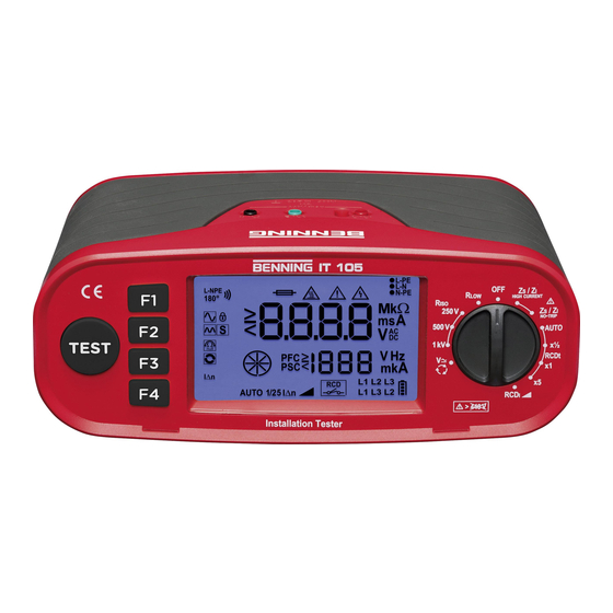
  • Page 3 Figure 1b: Function selector switch Fig. 1b: Commutateur de fonctions HIGH CURRENT Figura 1b: Selettore funzioni Fig. 1b: Functiekeuzeschakelaar E F G 250 V TRIP AUTO 500 V x½ 1 kV RCDt > 440 V 04/ 2020 BENNING IT 105...
  • Page 4 Figura 1c: Visualizzazione display Fig. 1c: Digitaal display Bild 2: -Messung Figure 2: measurement Fig. 2: Mesure de R blau schwarz blue black Figura 2: Misurazione R LOW-/ bleu noir Fig. 2: -meting nero blauw swart 04/ 2020 BENNING IT 105...
  • Page 5 Figura 4: Misurazione tensione, RCD e Z tramite cavo die misura con spina di sicurezza Fig. 4: Voltage-, RCD- en ZS/ZI-meting via testkabel met aardingscontactplug 04/ 2020 BENNING IT 105...
  • Page 6 Figure 6: measurement and PSC measurement (phase-phase) Fig. 6: Mesure Z et mesure PSC (phase- phase) Figura 6: Misurazione Z e misurazione PSC (fase-fase) Fig. 6: -meting en PSC-meting (fasefase) 04/ 2020 BENNING IT 105...
  • Page 7 Roterende veldtest (fasevolgorde) Bild 8: Batterie-/ Sicherungswechsel Figure 8: Battery/fuse replacement Fig. 8: Remplacement des piles et du fusible FF 1,6A Seriennummer 1000VDC Figura 8: Sostituzione batterie / fusibili serial number Fig. 8: Batterij en zekering vervangen 04/ 2020 BENNING IT 105...
  • Page 8: Table Des Matières

    Internationale, nationale und gegebenenfalls regionale Vorschriften der Elektrotechnik sind in jedem Fall einzuhalten. Einschlägige Kenntnisse der Elektrotechnik werden vorausgesetzt. Das Installationsprüfgerät BENNING IT 105 ist zur Messung in trockener Umgebung vorgesehen (näheres hierzu im Abschnitt 6: Umgebungsbedingungen). In der Bedienungsanleitung und auf dem BENNING IT 105 werden folgende Symbole verwendet:...
  • Page 9: Sicherheitshinweise

    Grenzwert gesunken ist. Trennen Sie das Prüfgerät vom Prüfobjekt und schalten Sie das Prüfgerät aus. Dieses Symbol auf dem BENNING IT 105 bedeutet, dass das BENNING IT 105 konform zu den EU-Richtlinien ist. Dieses Symbol erscheint in der Anzeige für entladene Batterien. Sobald das Batteriesymbol blinkt, tauschen Sie umgehend die Batterien gegen neue Batterien aus.
  • Page 10: Lieferumfang Und Optionales Zubehör

     Während der Messung keine Metallteile des Prüfobjektes berühren. Das Prüfgerät BENNING IT 105 ist direkt nach beendeter Prüfung von der elektrischen Anlage  zu trennen. Verwenden Sie ausschließlich, die im Lieferumfang des BENNING IT 105 enthaltenen Mess- ...
  • Page 11: Gerätebeschreibung

    (10194027) Das BENNING IT 105 benötigt sechs 1,5 V Mignon-Batterien/ Typ AA, IEC LR6 Hinweis auf optionales Zubehör: BENNING TA 5 40 m Messleitung mit Aufwickler und Handschlaufe, zur Messung von Schutz leiter ver- bindungen (044039) 4. Gerätebeschreibung siehe Bild 1a: Gerätefrontseite/ Geräteoberseite...
  • Page 12: Allgemeine Angaben

    Bei Umgebungstemperatur von 0 °C bis 40 °C, nicht kondensierend Lagerungstemperatur: Das BENNING IT 105 kann bei Tem pera turen von - 25 °C bis + 65 °C (Luftfeuchte 0 bis 90 %) gelagert werden. Dabei sind die Batterien aus dem Gerät herauszunehmen.
  • Page 13 - 0 %, + 10 % bei I∆N und 5 I∆N - 10 %, + 0 % bei ½ I∆N Auslösestrombereich: ½ I∆N - 1,1 I∆N (Typ AC, sinusförmig) ½ I∆N - 1,5 I∆N (Typ A, pulsierend) Auslösestromgenauigkeit: 10 % 04/ 2020 BENNING IT 105...
  • Page 14: Ein-, Ausschalten Des Benning It 105

    Prüfspitze mit TEST-Taste Die Prüfspitze mit integrierter TEST-Taste kann anstelle der schwarzen 4 mm Messleitung verwendet wer- den. Der Messvorgang kann somit über die TEST-Taste 4 am BENNING IT 105 oder über die TEST-Taste der Prüfspitze gestartet werden. 8.2 Spannung, Frequenz und Drehfeld (Phasenfolge) Mit dem Drehschalter 1 die gewünschte Funktion (V) A wählen.
  • Page 15: Isolationswiderstand (Riso )

    Widerstandswert an den Messspitzen < 20 kΩ beträgt. Die Funktion bleibt auch nach dem Ausschalten des Prüfgerätes gespeichert. Messleitungen gemäß Bild 2 am BENNING IT 105 anschließen und mit dem Prüfobjekt kontaktieren. Die Durchgangsprüfung startet automatisch, wenn über die Funktionstaste F4 3 die AUTO- Start-Funktion aktiviert wurde. Alternativ betätigen und halten Sie die TEST-Taste 4 , um eine Durchgangsprüfung zu starten.
  • Page 16: Schleifenimpedanz (Z S ) Und Leitungsimpedanz (Z I )

    Bei aktiviertem AUTO-Start wird die Messung automatisch nach 4 s. gestartet, nachdem das BENNING IT 105 an Netzspannung angeschlossen wurde. Zum Deaktivieren betätigen Sie erneut die Funktionstaste F4 3 . Messleitungen gemäß Bild 4, 5 oder 6 am BENNING IT 105 anschließen und mit dem Prüfobjekt kon- taktieren.
  • Page 17: Rcd-Prüfung

    Bei aktiviertem AUTO-Start wird die Messung automatisch nach 4 s. gestartet, nachdem das BENNING IT 105 an Netzspannung angeschlossen wurde. Zum Deaktivieren betätigen Sie erneut die Funktionstaste F4 3 . Messleitungen gemäß Bild 4, 5 oder 6 am BENNING IT 105 anschließen und mit dem Prüfobjekt kon- taktieren.
  • Page 18: (X½, X1, X5)

    ► 100 mA Messleitungen gemäß Bild 4 oder 5 am BENNING IT 105 an schlie ßen und mit dem Prüfobjekt kontaktieren. Betätigen Sie die TEST-Taste 4 , um die Messung zu starten. Schalten Sie den RCD nach jeder Auslösung wieder ein bis die Prüffolge beendet wurde.
  • Page 19: Auslösestrom Rcdi

       Messleitungen gemäß Bild 4 oder 5 am BENNING IT 105 an schließen und mit dem Prüfobjekt kontak- tieren. Betätigen Sie die TEST-Taste 4 , um die Messung zu starten. Das Hauptdisplay K zeigt die gemessene Auslösezeit an.
  • Page 20: Instandhaltung

    300mA ► 500 mA Messleitungen gemäß Bild 4 oder 5 am BENNING IT 105 an schließen und mit dem Prüfobjekt kontak- tieren. Betätigen Sie die TEST-Taste 4 , um die Messung zu starten. Das Hauptdisplay K zeigt den gemessenen Auslösestrom an.
  • Page 21: Umweltschutz

    So wechseln Sie die Sicherung (siehe Bild 8): Schalten Sie das BENNING IT 105 aus. Legen Sie das BENNING IT 105 auf die Frontseite und lösen Sie die Schrauben vom Batteriedeckel. Heben Sie den Batteriedeckel vom Unterteil ab. Heben Sie ein Ende der defekten Sicherung seitlich mit einem Schlitzschraubendreher aus dem Sicherungshalter.
  • Page 22 Operating manual BENNING IT 105 The BENNING IT 105 installation tester is a multifunctional tester for testing electrical installations in com- pliance with IEC 60364-6 (DIN VDE 0100-600) and EN 50110 (DIN VDE 0105-100) . The device is intended for the following measurements and tests:...
  • Page 23: Safety Note

    Disconnect the tester from the test object and switch off the tester. This symbol on the BENNING IT 105 means that the BENNING IT 105 complies with the EU directives.
  • Page 24: Scope Of Delivery And Optional Accessories

    Disconnect the BENNING IT 105 from the electrical system directly after the test is finished.  Only use the measuring leads included in the scope of delivery of the BENNING IT 105. Use the BENNING IT 105 only in compliance with the intended use specified in this docu- ...
  • Page 25: Description Of Installation Tester

    O ne fuse, nominal current rating 1.6 A, 1000 V, superfast-acting (FF), breaking capacity ≥ 30 kA, D = 6.3 mm, L = 32 mm (part no. 10194027). The BENNING IT 105 is powered by six mignon batteries 1.5 V (IEC LR6/ type AA). Note on optional accessories: BENNING TA 5 40 m measuring lead with rewinder and wrist strap, for measuring protective conductor connections (044039).
  • Page 26: General Information

    “Tester is overheated!”; please observe the relevant sections of this operating manual. N Symbol indicating a defective fuse 5. General information The BENNING IT 105 is intended for electrical safety tests in compliance with IEC 60364-6 (DIN VDE 0100-600) and EN 50110 (DIN VDE 0105-100). Appliance dimensions: (length x width x height) = 235 x 132 x 92 mm Appliance weight: 1370 g incl.
  • Page 27: Measuring With The Benning It 105

    8. Measuring with the BENNING IT 105 8.1 Preparations for measuring Operate and store the BENNING IT 105 only at the specified storage and operating temperatures. Avoid continuous insulation. Check the nominal voltages and nominal current on the safety measuring leads.
  • Page 28: Switching The Benning It 105 On/Off

    The test probe with integrated TEST key can be used instead of the black 4 mm measuring lead. Thus, the measuring process can be started via the TEST key 4 of the BENNING IT 105 or via the TEST key of the test probe.
  • Page 29: Insulating Resistance (Riso )

    Connect the measuring leads to the BENNING IT 105 as shown in figure 2 and apply them to the test object. The continuity test is started automatically if the AUTO start function has been enabled via the function key F4 3 .
  • Page 30: Loop Impedance (Z S ) And Line Impedance (Z I )

    Press the function key F4 3 again to disable the function. Connect the measuring leads to the BENNING IT 105 as shown in figures 4, 5 or 6 and apply them to the test object.
  • Page 31: Rcd Test

    Press the function key F4 3 again to disable the function. Connect the measuring leads to the BENNING IT 105 as shown in figures 4, 5 or 6 and apply them to the test object.
  • Page 32: Tripping Time Rcdt (X½, X1, X5)

    10 mA 30 mA 100 mA Connect the measuring leads to the BENNING IT 105 as shown in figures 4 or 5 and apply them to the test object. Press the TEST key 4 to start the measurement. Switch the RCD on again after each tripping until the test sequence is completed.
  • Page 33: Tripping Current Rcdi

       Connect the measuring leads to the BENNING IT 105 as shown in figures 4 or 5 and apply them to the test object. Press the TEST key 4 to start the measurement. The measured tripping time is shown on the main display K.
  • Page 34: Maintenance

    300mA ► 500 mA Connect the measuring leads to the BENNING IT 105 as shown in figures 4 or 5 and apply them to the test object. Press the TEST key 4 to start the measurement. The measured tripping time is shown on the main display K.
  • Page 35: Fuse Replacement

    Before opening the BENNING MM 12, ensure that it is not connected to a source of voltage!  Electrical danger! The BENNING IT 105 is protected against overload by means of an integrated fuse (1.6 A, 1000 V, super- fast-acting (FF), breaking capacity ≥ 30 kA, D = 6.3 mm, L = 32 mm (part no. 10194027). Proceed as follows to replace the fuses: Turn the rotating switch 1 to “OFF”.
  • Page 36 être respectées. Des connaissances pertinentes en matière d’électrotechnique sont sup- posées. Le BENNING IT 105 est conçu pour effectuer des mesures dans un environne ment sec (pour de plus amples informations, consulter la section « Conditions d’environnement »).
  • Page 37: Consignes De Sécurité

    Déconnectez l’appareil de contrôle de l’objet de contrôle et éteignez l’appareil de contrôle. Ce symbole sur le contrôleur BENNING IT 105 signifie que le BENNING IT 105 est conforme aux directives de l’UE. Ce symbole apparaît sur l‘affichage indiquant que la batterie est déchargée. Dès que le symbole de pile clignote, remplacez immédiatement les piles par des piles neuves.
  • Page 38: Contenu De L'emballage Et Accessoires En Option

    Le contenu de l’emballage de l’appareil BENNING IT 105 avec l’indice .01 comprend : 3.1 un BENNING IT 105 (douilles pour câble de mesure : noir, bleu, vert) (réf. 10220312) 3.2 un coffret de transport avec compartiment à accessoires (réf. 10198412) 3.3 une pointe de mesure avec touche TEST (réf.
  • Page 39: Description De L'appareil

    1,6 A, 1000 V, puissance de coupure ≥ 30 kA, D = 6,3 mm, L = 32 mm (réf. 10194027) Le BENNING IT 105 est alimenté par six piles rondes de 1,5 V/ type AA selon IEC LR6. Remarque concernant les pièces d‘usure : BENNING TA 5 câble de mesure (40 m) avec enrouleur et dragonne, pour la mesure des connexions...
  • Page 40: Indications Générales

    Avec une température de environnement de 0 °C à 40 °C, sans condensation Température de stockage: Le BENNING IT 105 peut être stocké à des tem pératures de - 25 °C à + 65 °C (humidité de l’air de 0 à 90 %). Pour cela, il faut retirer la pile hors de l’appareil.
  • Page 41: Contrôle Rcd

    - 10 %, + 0 % pour ½ I∆N Plage de courant de déclenchement : ½ I∆N - 1,1 I∆N (type AC, sinusoïdal) ½ I∆N - 1,5 I∆N (type A, pulsatoire) Précision du courant de déclenchement : 10 % 04/ 2020 BENNING IT 105...
  • Page 42: Mesure Avec Le Benning It

    Sélectionnez la fonction souhaitée (V) A au moyen du commutateur rotatif 1 . Raccordez les câbles de mesure à l’appareil BENNING IT 105 comme montré dans les figures 3, 4, 5 ou 7 et mettez-les en contact avec l’objet de contrôle.
  • Page 43: Résistance D'isolement (Riso )

    éteint. Raccordez les câbles de mesure à l’appareil BENNING IT 105 comme montré dans la figure 2 et mettez-les en contact avec l’objet de contrôle. Le test de continuité est lancé automatiquement, si la fonction de démarrage AUTO a été activée au moyen de la touche de fonction F4 3 .
  • Page 44: Impédance De Boucle (Z S ) Et Impédance De Ligne

    Lorsque le démarrage AUTO est activé, la mesure est lancée automatiquement 4 secondes après que l’appareil BENNING IT 105 a été branché à la tension secteur. Afin de désactiver la fonction, appuyez de nouveau sur la touche de fonction F4 3 .
  • Page 45: Mesures Avec Un Faible Courant D'essai

    Lorsque le démarrage AUTO est activé, la mesure est lancée automatiquement 4 secondes après que l’appareil BENNING IT 105 a été branché à la tension secteur. Afin de désactiver la fonction, appuyez de nouveau sur la touche de fonction F4 3 .
  • Page 46: (Auto)

    Fonction « RECALL » : Chaque fois une touche est actionnée, les valeurs mesurées de la dernière mesure « AUTO » sont affichées sur l’écran numérique. ½ x I∆N pour 0° ▼ ½ x I∆N pour 180° ▼ I∆N pour 0° ▼ I∆N pour 180° ▼ 5 x I∆N pour 0° ▼ 5 x I∆N pour 180° ▼ Démarrage de la mesure « AUTO » 04/ 2020 BENNING IT 105...
  • Page 47 ► 100 mA Raccordez les câbles de mesure à l’appareil BENNING IT 105 comme montré dans les figures 4 ou 5 et mettez-les en contact avec l’objet de contrôle. Appuyez sur la touche « TEST » 4 ) afin de lancer la mesure.
  • Page 48: Courant De Déclenchement Rcdi

    Déconnectez tous les câbles de raccordement de l’appareil. 9.1 Rangement sûr de l‘appareil Dans certaines conditions, la sécurité de travail avec le BENNING IT 105 peut ne plus être garantie ; par exemple dans les cas suivants : dommages visibles sur le boîtier, erreurs lors des mesures, conséquences visibles d‘un stockage prolongé...
  • Page 49: Nettoyage

     trique ! Le BENNING IT 105 est alimenté par six piles rondes de 1,5 V (IEC LR6/ type AA). Il est nécessaire de remplacer les piles dès que le symbole de pile I clignote sur l’écran. Remplacez les piles de la manière suivante (voir fig. 8) Amenez le commutateur rotatif 1 sur la position «...
  • Page 50: Pièces De Rechange

    9.6 Pièces de rechange Fusible 1,6 A, 1000 V, puissance de coupure ≥ 30 kA, D = 6,3 mm, L = 32 mm Réf. 10194027 10. Information sur l’environnement Une fois le produit en fin de vie, veuillez le déposer dans un point de recyclage approprié. 04/ 2020 BENNING IT 105...
  • Page 51 Istruzioni d’uso BENNING IT 105 Il tester di installazione BENNING IT 105 è un apparecchio multifunzionale per il controllo degli impianti elettrici ai sensi di IEC 60364-6 (DIN VDE 0100-600) e EN 50110 (DIN VDE 0105-100). Possono essere eseguite le seguenti misurazioni e verifiche:...
  • Page 52: Avvertenze Sulla Sicurezza

    Scollegare il tester dall’oggetto di prova e spegnere il tester. Questo simbolo su BENNING IT 105 significa che BENNING IT 105 è conforme alla normativa europea.
  • Page 53: Fornitura Ed Accessori Opzionali

    3. Fornitura ed accessori opzionali Fanno parte della dotazione standard di BENNING IT 105 con livello indice 01: 3.1 1 pz. tester di installazione BENNING IT 105 (connettori linee di misura: nero, blu, verde) (10220312) 3.2 1 pz. valigetta di trasporto con scomparto accessori (10198412) 3.3 1 pz.
  • Page 54: Descrizione Apparecchio

    BENNING IT 105 viene alimentato da sei batterie micro 1,5 V / tipo AA IEC LR6 Nota sugli accessori opzionali: BENNING TA 5: Linea di misura 40 m con avvolgitore e occhiello manuale, per la misurazione di con- nessioni di conduttori di protezione (044039) 4.
  • Page 55: Condizioni Ambientali

    In presenza di temperature ambiente da 0 °C a 40 °C, non genera condensa Temperatura di stoccaggio: il BENNING IT 105 essere immagazzinato a temperature da - 25 °C a +65 °C (umidità dell’aria da 0 a 90%). In tal caso si deve rimuovere le batterie dall’apparecchio.
  • Page 56: Prova Rcd

    195 V - 253 V, 45 Hz - 65 Hz Corrente di prova nominale: 10 mA, 30 mA, 100 mA, 300 mA (tipo AC, A) 500 mA (tipo AC) Precisione della corrente di guasto: - 0 %, + 10 % con IΔN e 5 IΔN - 10 %, + 0 % e ½ IΔN Campo corrente di intervento: ½ IΔN - 1,1 IΔN (Tipo AC, sinusoidale) ½ IΔN - 1,5 IΔN (Tipo A, pulsante) Precisione della corrente di intervento: 10 % 04/ 2020 BENNING IT 105...
  • Page 57: Misure Con Il Benning It

    8.2 Tensione, frequenza e sequenza di fase Con il commutatore rotante 1 selezionare la funzione (V) A desiderata. Collegare le linee di misura in base alla figura 3, 4, 5 o 7 sul BENNING IT 105 e metterle in contatto con l’oggetto di prova.
  • Page 58: Resistenza Di Isolamento (Riso )

    Collegare le linee di misura in base alla figura 2 sul BENNING IT 105 e metterle in contatto con l’og- getto di prova. Il test di continuità si avvia automaticamente, quando attraverso il tasto di funzione F4 3 viene attivata la funzione di avvio AUTO.
  • Page 59: Impedenza Dell'anello Di Guasto

    BENNING IT 105 è stato collegato alla tensione di rete. Per la disattivazione riattivare il tasto funzione F4 3 . Collegare le linee di misura in base alla figura 4, 5 o 6 sul BENNING IT 105 e metterle in contatto con l’oggetto di prova.
  • Page 60: Misurazione Con Corrente Di Prova Bassa

    BENNING IT 105 è stato collegato alla tensione di rete. Per la disattivazione riattivare il tasto funzione F4 3 . Collegare le linee di misura in base alla figura 4, 5 o 6 sul BENNING IT 105 e metterle in contatto con l’oggetto di prova.
  • Page 61: Tempo Di Intervento Rcd (Auto)

    Corrente di guasto nominale IΔN (F4): Tramite il tasto funzione F4 è possibile selezionare la corrente di guasto nominale: Correnti di guasto nominali disponibili (corrente di prova sinusoidale) 10 mA ► 30 mA ► 100 mA 04/ 2020 BENNING IT 105...
  • Page 62: Tempo Di Intervento Rcd

    Collegare le linee di misura in base alla figura 4 o 5 sul BENNING IT 105 e metterle in contatto con l’oggetto di prova. Attivare il tasto TEST 4 , per avviare la misurazione. Riattivare l’RCD dopo ogni attivazione fino al termine della sequenza di prova.
  • Page 63: Manutenzione

    300mA ► 500 mA Collegare le linee di misura in base alla figura 4 o 5 sul BENNING IT 105 e metterle in contatto con l’oggetto di prova. Attivare il tasto TEST 4 , per avviare la misurazione. Il display principale K mostra il corrente di intervento misurato.
  • Page 64: Sostituzione Della Batteria

    Prima di aprire il BENNING IT 105 assicurarsi che esso non sia sotto tensione! Pericolo di  scariche elettriche! BENNING IT 105 è protetto contro i sovraccarichi tramite un fusibile incorporato (1,6 A, 1000 V, FF, potere di interruzione ≥ 30 kA D = 6,3 mm, L = 32 mm), (10194027) Procedere come segue per sostituire il fusibile (vedere Figura 8): Spegnere BENNING IT 105.
  • Page 65 Internationale, nationale en mogelijk regionale elektrotechnische voorschriften moeten in alle gevallen worden nageleefd. Relevante kennis van elektrotechniek is vereist. De BENNING IT 105 is bedoeld voor metingen in droge ruimtes (zie hiervoor punt. 6: Gebruiksomstandigheden). In de gebruiksaanwijzing en op de BENNING IT 105 worden de volgende symbolen gebruik:...
  • Page 66: Veiligheidsvoorschriften

    Koppel de tester los van het testobject en schakel de tester uit. Dit symbool op de BENNING IT 105 betekent dat de BENNING IT 105 in overeenstemming met de EU-richtlijnen is.
  • Page 67: Leveringsomvang En Optionele Accessoires

    Tijdens isolatieweerstandsmetingen kunnen hoge elektrische spanningen aanwezig zijn aan de meetpunten.  Raak metalen delen van het testobject tijdens de meting niet aan. Het BENNING IT 105-testapparaat moet onmiddellijk na het einde van de test van het elek-  trische systeem worden losgekoppeld. ...
  • Page 68: Beschrijving Van Het Apparaat

    Voorts is de BENNING IT 105 voorzien van een smeltzekering tegen overbelasting, voor een nomi- nale stroom van 1,6 A, 1000 V, FF, scheidingsvermogen ≥ 30 kA, D = 6,3 mm, L = 32 mm (ond. nr. 10194027) De BENNING IT 105 wordt gevoed door zes batterijen van 1,5 V (mignon, IEC LR6, AA) Opmerking t.a.v. optionele onderdelen: BENNING TA 5 40 m meetsnoer met opwikkelaar en handlus, voor het meten van de aardverbindingen (044039) 4.
  • Page 69: Algemene Kenmerken

    IEC 60364-6 en EN 50110. - Afmetingen van het apparaat: (L x B x H) = 235 x 132 x 92 mm Gewicht: 1370 g met batterijen 6. Gebruiksomstandigheden De BENNING IT 105 is bedoeld om gebruikt te worden voor metingen in droge ruimtes Barometrische hoogte bij metingen: 2000 m maximaal - Overspanningscategorie IEC 61010-1 → 300 V categorie III Beschermingsgraad stofindringing: 2 Beschermingsgraad: IP 40 (EN 60529) Betekenis IP 40: Het eerste cijfer (4);...
  • Page 70 - 0 %, + 10 % bij I∆N en 5 I∆N - 10 %, + 0 % bij ½ I∆N Uitschakelstroombereik: ½ I∆N - 1,1 I∆N (type AC, sinusvormig) ½ I∆N - 1,5 I∆N (type A, pulserend) Nauwkeurigheid uitschakelstroom: 10 % 04/ 2020 BENNING IT 105...
  • Page 71: Meten Met De Benning It 105

    Sonde met TEST-knop De testsonde met geïntegreerde TEST-knop kan worden gebruikt in plaats van de zwarte 4 mm-testkabel. Het meetproces kan dus worden gestart via de TEST-knop 4 op de BENNING IT 105 of via de TEST-knop op de testsonde.
  • Page 72: Isolatieweerstand (Riso )

    Als AUTO Start wordt geactiveerd, wordt de continuïteitstest automatisch gestart als de toegepaste weer- stand bij de meetpunten < 20 kΩ is. De functie blijft opgeslagen, zelfs nadat de tester is uitgeschakeld. Verbind de meetsnoeren met de BENNING IT 105 volgens afb. 2 en maak contact met het testobject. De continuïteitstest start automatisch wanneer de AUTO-start-functie wordt geactiveerd via de functie- toets F4 3 .
  • Page 73: Meting Met Hoge Teststroom

    Wanneer AUTO Start wordt geactiveerd, start de meting automatisch 4 seconden nadat de BENNING IT 105 op netspanning is aangesloten. Druk opnieuw op de functietoets F4 3 om te deactiveren. Verbind de meetsnoeren volgens afbeelding 4, 5 of 6 met de BENNING IT 105 en maak contact met het testobject.
  • Page 74: Rcd-Test

    Wanneer AUTO Start wordt geactiveerd, start de meting automatisch 4 seconden nadat de BENNING IT 105 op netspanning is aangesloten. Druk opnieuw op de functietoets F4 3 om te deactiveren. Verbind de meetsnoeren met de BENNING IT 105 volgens afb. 4, 5 of 6 en maak contact met het testobject.
  • Page 75 30 mA ► 100 mA Verbind de meetsnoeren met de BENNING IT 105 volgens afb. 4 of 5 en maak contact met het test- object. Houd de TEST-knop 4 ingedrukt om een meting te starten. Schakel de RCD na elke activering weer in totdat de testprocedure is voltooid.
  • Page 76: Uitschakelstroom Rcdi

       Verbind de meetsnoeren met de BENNING IT 105 volgens afb. 4 of 5 en maak contact met het test- object. Houd de TEST-knop 4 ingedrukt om een meting te starten. De hoofddisplay K toont de gemeten uitschakeltijd.
  • Page 77: Onderhoud

    300mA ► 500 mA Verbind de meetsnoeren met de BENNING IT 105 volgens afb. 4 of 5 en maak contact met het test- object. Houd de TEST-knop 4 ingedrukt om een meting te starten. De hoofddisplay K toont de gemeten uitschakeltijd.
  • Page 78 Deze zekering wordt als volgt gewisseld (zie fig. 8): Zet de draaischakelaar 1 in de positie “OFF”. Leg de BENNING IT 105 op de voorkant en draai de schroef van het batterijdeksel los. Neem het batterijdeksel van het apparaat weg.
  • Page 79 Benning Elektrotechnik & Elektronik GmbH & Co. KG Münsterstraße 135 - 137 D - 46397 Bocholt Phone: +49 (0) 2871 - 93 - 0 • Fax: +49 (0) 2871 - 93 - 429 www.benning.de • E-Mail: duspol@benning.de...

Ce manuel est également adapté pour:

044105

Table des Matières