Télécharger Imprimer la page

Publicité

Les langues disponibles

Les langues disponibles

Liens rapides

790r
2-Cycle Gas Trimmer/Brushcutter
OPERATOR'S MANUAL
FOR QUESTIONS, CALL 1-800-345-8746 in U.S. or
1-800-668-1238 in CANADA
www.RyobiOutdoor.com
IMPORTANT MANUAL
DO NOT THROW AWAY

Publicité

loading

Sommaire des Matières pour Ryobi 790r

  • Page 1 790r 2-Cycle Gas Trimmer/Brushcutter OPERATOR’S MANUAL FOR QUESTIONS, CALL 1-800-345-8746 in U.S. or 1-800-668-1238 in CANADA www.RyobiOutdoor.com IMPORTANT MANUAL DO NOT THROW AWAY...
  • Page 2 THIS PRODUCT IS COVERED BY ONE OR MORE CONTENTS OF CARTON US PATENTS, OTHER PATENTS PENDING. • Model 790r Trimmer/Brushcutter ∆ Large Bump Head Cutting Attachment ∆ 4-Tooth Brush Blade ∆ J-Handle and Hardware •...
  • Page 3 CALIFORNIA PROPOSITION 65 WARNING WARNING THE ENGINE EXHAUST FROM THIS PRODUCT CONTAINS CHEMICALS KNOWN TO THE STATE OF CALIFORNIA TO CAUSE CANCER, BIRTH DEFECTS OR OTHER REPRODUCTIVE HARM. SPARK ARRESTOR NOTE: For users on U.S. Forest Land and in the states of California, Maine, Oregon and Washington. All U.S. Forest Land and the state of California (Public Resources Codes 4442 and 4443), Oregon and Washington require, by law that certain internal combustion engines operated on forest brush and/or grass-covered areas be equipped with a spark arrestor, maintained in effective working order, or the engine be constructed, equipped and maintained for the...
  • Page 4 RULES FOR SAFE OPERATION • IMPORTANT SAFETY INFORMATION • READ ALL INSTRUCTIONS • Always stop the engine and allow it to cool before filling the fuel tank. Never remove the fuel tank cap or add fuel when the engine is hot. Never operate the unit WARNING : When using the unit, you must without the fuel cap securely in place.
  • Page 5 RULES FOR SAFE OPERATION • Do not overreach. Always keep proper footing and • Do not attempt to touch or stop the blade when it is balance. rotating. • Always hold the unit with both hands when operating. • A coasting blade can cause injury while it continues to Keep a firm grip on both handles or grips.
  • Page 6 RULES FOR SAFE OPERATION SAFETY AND INTERNATIONAL SYMBOLS This operator's manual describes safety and international symbols and pictographs that may appear on this product. Read the operator's manual for complete safety, assembly, operating and maintenance and repair information. SYMBOL MEANING SYMBOL MEANING •...
  • Page 7 • Cutting weeds and light bush of up to 1/2 inch in As a trimmer: diameter • Cutting grass and light weeds Other optional accessories may be used with the 790r. • Edging Refer to Operating the EZ-Link System for a list of add-ons. • Decorative trimming around trees, fences, etc.
  • Page 8 ASSEMBLY INSTRUCTIONS On some units, the J-handle may be pre-installed. In this INSTALL THE HARNESS case you must loosen screws and adjust the handle to fit the operator. Go to step 5 if the J-handle is pre-installed. WARNING: Always use the shoulder harness when using the cutting blade to INSTALL AND ADJUST THE J-HANDLE avoid serious personal injury.
  • Page 9 ASSEMBLY INSTRUCTIONS 2. Hold the locking rod in place by grasping it next to Cutting the boom of the unit (Fig. 9). (3) Screws Attachment Shield 3. While holding the locking rod, remove the cutting attachment by turning it clockwise off of the output shaft (Fig.
  • Page 10 ASSEMBLY INSTRUCTIONS 5. Make sure that the cutting blade is centered on the REMOVE THE CUTTING BLADE AND pilot step and sitting flat against the output shaft INSTALL THE CUTTING ATTACHMENT bushing (Fig. 12). WARNING: To avoid serious personal injury, always wear gloves while handling or WARNING: If the cutting blade is off- installing the blade.
  • Page 11 OIL AND FUEL INFORMATION OIL AND FUEL MIXING INSTRUCTIONS Thoroughly mix the proper ratio of 2-cycle engine oil with unleaded gasoline in a separate fuel can. Use a 32:1 Old and/or improperly mixed fuel are the main reasons fuel/oil ratio. Do not mix them directly in the engine fuel for the unit not running properly.
  • Page 12 STARTING/STOPPING INSTRUCTIONS STARTING INSTRUCTIONS On/Off Stop Control Stop/Off (O) Start/On (I) WARNING: Operate this unit only in a well- ventilated outdoor area. Carbon monoxide Throttle Lock-Out exhaust fumes can be lethal in a confined area. WARNING: Avoid accidental starting. Make sure you are in the starting position when pulling the starter rope (Fig.
  • Page 13 OPERATING INSTRUCTIONS ™ 2. While firmly holding the add-on, push it straight into OPERATING THE EZ-LINK SYSTEM the EZ-Link™ coupler (Fig. 20). The EZ-Link™ system enables the use of these optional NOTE: Aligning the release button with the guide recess Add-Ons: will help installation (Fig.
  • Page 14 OPERATING INSTRUCTIONS HOLDING THE TRIMMER Each time the head is bumped, about 1 inch (25.4 mm) of trimming line is released. A blade in the cutting attachment shield will cut the line to the proper length if WARNING: Always wear eye, hearing, foot excess line is released.
  • Page 15 OPERATING INSTRUCTIONS DECORATIVE TRIMMING WARNING: The blade continues to spin after the engine is turned off. The coasting blade Decorative trimming is accomplished by removing all can seriously cut you if accidentally touched. vegetation around trees, posts, fences and more. Rotate the whole unit so that the cutting attachment is at •...
  • Page 16 MAINTENANCE AND REPAIR INSTRUCTIONS MAINTENANCE SCHEDULE NOTE: Maintenance, replacement, or repair of the emission control devices and system may be Perform these required maintenance procedures at the performed by any non-road engine repair frequency stated in the table. These procedures should establishment, individual or authorized service also be a part of any seasonal tune-up.
  • Page 17 MAINTENANCE AND REPAIR INSTRUCTIONS For Use with Single For Use with SplitLine™ 9. Insert the end of the line into the open hole in the Line ONLY or Single Line inner reel and pull the line tight to make the loop as small as possible (Fig.
  • Page 18 MAINTENANCE AND REPAIR INSTRUCTIONS INSTALLING A PREWOUND REEL Cleaning the Air Filter Clean and re-oil the air filter every 10 hours of operation. 1. Hold the outer spool with one hand and unscrew the It is an important item to maintain. Failure to maintain the bump knob clockwise (Fig.
  • Page 19 MAINTENANCE AND REPAIR INSTRUCTIONS Reinstalling the Air Filter/Muffler Cover 1. Place the air filter/muffler cover over the back of the carburetor and muffler. Align the screw holes. Exhaust Spark Bolts Gasket Arrestor 2. Insert the four (4) screws into the holes in the air filter/muffler cover (Fig.
  • Page 20 MAINTENANCE AND REPAIR INSTRUCTIONS CARBURETOR ADJUSTMENT NOTE: The cutting attachment should not rotate when the engine idles. The idle speed of the engine is adjustable through the air filter/muffler cover (Fig. 43). 3. If the cutting attachment rotates when the engine idles, turn the idle speed screw counterclockwise NOTE: Careless adjustments can seriously damage your 1/8 of a turn at a time (as needed), to reduce idle...
  • Page 21 MAINTENANCE AND REPAIR INSTRUCTIONS CLEANING TRANSPORTING • Allow the engine to cool before transporting. WARNING: To avoid serious personal injury, always turn your trimmer off and allow it to • Drain fuel from unit. cool before you clean or service it. •...
  • Page 22 TROUBLESHOOTING ENGINE WILL NOT START C A U S E A C T I O N Empty fuel tank Fill fuel tank with properly mixed fuel Primer bulb wasn't pressed enough Press primer bulb fully and slowly 10 times Engine is flooded Squeeze the trigger and pull the starter rope Old or improperly mixed fuel Drain gas tank and add fresh fuel mixture...
  • Page 23 SPECIFICATIONS ENGINE* Engine Type............................Air-Cooled, 2-Cycle Stroke ..............................1.25 in. (31.75 mm) Displacement.............................. 1.9 cu in. (31 cc) Clutch Type ................................. Centrifugal Idle Speed RPM ............................2,800-3,600 rpm Operating RPM ..............................6,100+ rpm Ignition Type................................Electronic Ignition Switch ........................... Momentary Rocker Switch Spark Plug Gap ............................
  • Page 24 NOTES...
  • Page 25 EPA Emission Control Warranty Statement Your Warranty Rights and Obligations The Environmental Protection Agency and MTD SOUTHWEST INC (MTD) are pleased to explain the emission control system warranty on your 2002 and later small off-road engine. New small off-road engines must be designed, built and equipped to meet stringent anti-smog standards.
  • Page 26 P.O. Box 361131 MTD reserves the right to change or improve the design of Cleveland, OH 44136-0019 any RYOBI Product without assuming any obligation to modify any product previously manufactured. SAVE THESE INSTRUCTIONS FOR FUTURE REFERENCE. FOR QUESTIONS CALL 1-800-345-8746 IN U.S.
  • Page 27 790r Désherbeuse/débroussailleuse à gaz à 2-temps MANUEL DE L'UTILISATEUR SI VOUS AVEZ DES QUESTIONS, APPELEZ LE 1-800-345-8746 aux ÉTATS-UNIS, ou le 1-800-668-1238 au CANADA www.RyobiOutdoor.com MANUEL IMPORTANT À NE PAS JETER...
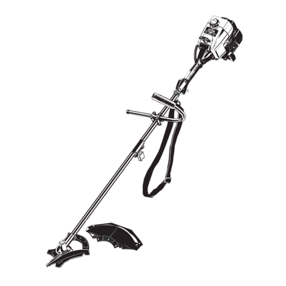
  • Page 28 REMARQUE: TOUT SERVICE SOUS GARANTIE NÉCESSITE CONTENU DE L'EMBALLAGE UNE PREUVE D'ACHAT • Désherbeuse/débroussailleuse modèle 790r ∆ Accessoire de coupe Bump Head de grande taille Prenez soin de lire et de bien comprendre ce manuel avant de démarrer ou de faire fonctionner cet ∆...
  • Page 29 PROPOSITION 65 DE CALIFORNIE AVERTISSEMENT LES GAZ D'ÉCHAPPEMENT DU MOTEUR DE CET APPAREIL CONTIENNENT DES PRODUITS CHIMIQUES CONSIDÉRÉS PAR L'ÉTAT DE CALIFORNIE COMME POUVANT CAUSER LE CANCER, DES MALFORMATIONS CONGÉNITALES OU D'AUTRES EFFETS NOCIFS SUR L'APPAREIL DE REPRODUCTION PARE-ÉTINCELLES NOTE : À l'intention des utilisateurs opérant dans les terres forestières des États-Unis et dans les états de Californie, du Maine, de l'Orégon et de Washington.
  • Page 30 CONSIGNES DE SÉCURITÉ • IMPORTANTES CONSIGNES DE SÉCURITÉ • LIRE TOUTES LES INSTRUCTIONS AVANT • Évitez de créer une source d'allumage pour le carburant déversé. Ne démarrez pas le moteur avant que les vapeurs UTILISATION de carburant ne se soient dissipées. •...
  • Page 31 CONSIGNES DE SÉCURITÉ • Ne touchez pas le moteur, le boîtier d'engrenages ni le • Avec une lame à broussailles, ne coupez rien de plus épais silencieux. Ces pièces deviennent très chaudes à que 1,3 cm (1/2 po) au risque de provoquer un recul violent. l'utilisation.
  • Page 32 CONSIGNES DE SÉCURITÉ SYMBOLES DE SÉCURITÉ ET INTERNATIONAUX Ce manuel de l'utilisateur décrit les symboles et pictogrammes de sécurité et internationaux pouvant apparaître sur ce produit. Consultez le manuel de l'utilisateur pour les informations concernant la sécurité, le montage, le fonctionnement, l'entretien et les réparations.
  • Page 33 • Coupe de mauvaises herbes et broussailles légères de 1,3 cm (1/2") de diamètre maximum • Coupe d'herbe et de mauvaises herbes légères D'autres accessoires peuvent être utilisés avec le 790R. • Coupe de bordures Voir la liste d'accessoires. • Taille autour des arbres, des clôtures, etc.
  • Page 34 INSTRUCTIONS DE MONTAGE INSTALLATION ET RÉGLAGE DE LA POIGNÉE EN J INSTALLER LE HARNAIS 1. Placez la poignée en J entre les brides supérieure et AVERTISSEMENT : portez toujours le harnais médiane (Fig. 1). d'épaule lorsque vous utilisez la lame de coupe afin d'éviter de vous blesser.
  • Page 35 INSTRUCTIONS DE MONTAGE 2. Maintenez la tige de blocage en place en la Protecteur d'accessoire de saisissant près du bras de l’appareil (Fig. 9). (3) vis coupe 3. Tout en tenant la tige de blocage, retirez l’accessoire de coupe de l’arbre de sortie en le tournant à droite (Fig.
  • Page 36 INSTRUCTIONS DE MONTAGE RETIRER LA LAME DE COUPE ET 5. Assurez-vous que la lame de coupe est centrée sur le INSTALLER L'ACCESSOIRE DE COUPE pas de guidage et qu'elle repose à plat contre la bague de l'arbre de sortie (Fig. 12). Retirer la lame de coupe AVERTISSEMENT : si la lame de coupe AVERTISSEMENT : pour éviter des...
  • Page 37 INFORMATIONS SUR L'HUILE ET LE CARBURANT MÉLANGE D'HUILE ET DE CARBURANT Mélangez soigneusement l'huile moteur 2-temps avec de l'essence sans plomb dans un bidon séparé. Utilisez En général, si l'appareil ne fonctionne pas correctement, un rapport 32:1 d'essence/huile. Ne les mélangez pas c'est que le carburant est vieux ou mal mélangé.
  • Page 38 INSTRUCTIONS DE DÉMARRAGE ET ARRÊT Stop/Arrêt (O) Commande Marche/Arrêt Stop INSTRUCTIONS DE DÉMARRAGE Démarrage/Allumage (I) AVERTISSEMENT : faites uniquement marcher l'appareil dans un lieu extérieur bien Déverrouilleur de aéré. Les fumées d'échappement d'oxyde de manette des gaz carbone peuvent être fatales dans un lieu confiné.
  • Page 39 MODE D'EMPLOI FONCTIONNEMENT DU EZ-Link 2. Tenez fermement l'accessoire et enfoncez-le tout droit dans le coupleur EZ-Link (Fig. 20). Le système EZ-Link permet d'utiliser ces accessoires optionnels : NOTE :aligner le bouton de déclenchement avec le renfoncement-guide facilitera l'installation (Fig. 19). Souffleuse/aspirateur .
  • Page 40 MODE D'EMPLOI Chaque fois que vous donnez un coup sur la tête, vous TENUE DE LA DÉSHERBEUSE déroulez environ 25,4 mm (1 po) de fil. La lame du AVERTISSEMENT : portez toujours des protecteur d'accessoire de coupe est conçue pour couper protections (yeux, oreilles, pieds et corps) le fil à...
  • Page 41 MODE D'EMPLOI COUPE DÉCORATIVE AVERTISSEMENT : la lame continue de tourner à vide une fois le moteur éteint et La coupe décorative consiste à déblayer la végétation peut vous blesser sérieusement si vous la autour des arbres, des bornes, des clôtures, etc. touchez accidentellement.
  • Page 42 ENTRETIEN ET RÉPARATIONS REMARQUE : certaines procédures d'entretien REMARQUE: l'entretien, le remplacement ou la nécessitent des compétences ou des outils réparation des dispositifs et systèmes particuliers. Si vous n'êtes pas sûr de pouvoir les antipollution peuvent être effectués par tout entreprendre, emmenez votre appareil dans un atelier, technicien ou concessionnaire agréé...
  • Page 43 ENTRETIEN ET RÉPARATIONS Utiliser avec le SplitLine 9. Insérez l’extrémité du fil dans le trou ouvert du Utiliser avec le fil simple ou le fil simple UNIQUEMENT moulinet et tirez sur le fil pour que la boucle soit le plus petit possible (Fig. 33). Trous allongés 10.
  • Page 44 ENTRETIEN ET RÉPARATIONS Installation d'un moulinet prérembobiné NETTOYAGE DU FILTRE Á AIRE 1. Tenez la bobine extérieure d'une main et dévissez le Nettoyez et relubrifiez le filtre à air à toutes les 10 heures bouton de butée vers à droite (Fig. 27). Inspectez le de fonctionnement.
  • Page 45 ENTRETIEN ET RÉPARATIONS Réinstallation du filtre à air/couvercle du Pare-étincelles silencieux Joint 1. Placez le filtre à air/couvercle du silencieux sur Boulons d'échappement l'endos du carburateur et du silencieux. Alignez les trous à vis. 2. Insérez les quatre (4) vis dans les trous du filtre à air/couvercle du silencieux (Fig.
  • Page 46 ENTRETIEN ET RÉPARATIONS RÉGLAGE DU CARBURATEUR REMARQUE : l'accessoire de coupe ne devrait pas tourner lorsque le moteur est au ralenti. Le régime ralenti du moteur est réglable par le couvercle du filtre à air/silencieux (Fig. 43). 3. S'il tourne, dévissez la vis de ralenti de 1/8 de tour à la fois (selon le besoin) pour réduire la vitesse de ralenti.
  • Page 47 ENTRETIEN ET RÉPARATIONS NETTOYAGE TRANSPORT • Laissez le moteur refroidir avant le transport. AVERTISSEMENT: pour éviter des blessures graves, éteignez toujours • Attachez bien l'appareil lors du transport. l'appareil et laissez-le refroidir avant tout • Videz tout le carburant de l’appareil. nettoyage ou entretien.
  • Page 48 DÉPANNAGE LE MOTEUR REFUSE DE DÉMARRER C A U S E S O L U T I O N Réservoir de carburant vide Remplissez-le de carburant bien mélangé. La poire d'amorçage n'a pas été pressée assez fort Pressez-la complètement et lentement de 10 fois Moteur noyé...
  • Page 49 CARACTÉRISTIQUES MOTEUR* Type de moteur..........................Refroidi par air, 2-temps Course ..............................31,75 mm (1,25 po) Cylindrée ................................ 31 cc (1,9 po Type d'embrayage ............................... Centrifuge Régime ralenti ............................2.800-3.600 tr/min Régime de fonctionnement ..........................6.100+ tr/min Type d'allumage..............................Électronique Contact d'allumage ..........................Interrupteur berceau Écartement de la bougie..........................
  • Page 50 REMARQUES...
  • Page 51 Garantie portant sur les normes antipollution de l'EPA Vos droits et obligations en vertu de cette garantie La Environmental Protection Agency et MTD SOUTHWEST INC (MTD) ont le plaisir de présenter la garantie du dispositif antipollution des petits moteurs à usage tout-terrain datant de 2002 et au-delà. Les nouveaux petits moteurs à...
  • Page 52 MTD LLC canaux agréés de distribution à l’exportation. MTD se réserve la droit de modifier ou d’améliorer la P.O. Box 361131 ® RYOBI conception de tout produit sans assumer l’obligation de modifier tout produit d’une fabrication plus Cleveland, OH 44136-0019 ancienne.
  • Page 53 790r Recortador / Cortamalezas de 2 ciclos a Gasolina MANUAL DEL OPERADOR SI TIENE PREGUNTAS, LLAME AL 1-800-345-8746 en EE.UU. o al 1-800-668-1238 en CANADA www.RyobiOutdoor.com ESTE MANUAL ES IMPORTANTE NO LO DESECHE...
  • Page 54 CONTENIDO DE LA CAJA ESTE PRODUCTO ESTA CUBIERTO POR UNA O MAS • Recortador / Cortador de malezas modelo 790r PATENTES DE EE.UU., OTRAS PATENTES EN ∆ Accesorio de corte de Bump Head grande TRAMITE.
  • Page 55 ADVERTENCIA DE LA PROPOSICIÓN 65 DE CALIFORNIA ADVERTENCIA LAS EMISIONES DEL MOTOR DE ESTE PRODUCTO CONTIENEN SUBSTANCIAS QUIMICAS QUE EL ESTADO DE CALIFORNIA CONOCE COMO CAUSANTES DE CANCER, DEFECTOS DE NACIMIENTO U OTROS DAÑOS REPRODUCTIVOS. AMORTIGUADOR DE CHISPAS NOTA: Para los usuarios en tierras forestales de los EE.UU. y en los estados de California, Maine, Oregon y Washington.
  • Page 56 NORMAS PARA UNA OPERACION SEGURA • IMPORTANTE INFORMACION DE SEGURIDAD • LEA TODAS LAS INSTRUCCIONES • Aleje la unidad a por lo menos 30 pies (9.1 m.) del lugar de carga de combustible antes de arrancar el motor. No fume, ANTES DE LA OPERACION mantenga las chispas y las llamas abiertas lejos del área mientras carga el combustible u opera la unidad.
  • Page 57 NORMAS PARA UNA OPERACION SEGURA • Apague siempre el motor cuando demore el corte o mientras • Si golpea o se enreda con un objeto extraño, detenga el camina entre zonas de corte. motor de inmediato y verifique si hay daños. Haga reparar todos los daños antes de intentar volver a operar la unidad.
  • Page 58 NORMAS PARA UNA OPERACION SEGURA SIMBOLOS DE SEGURIDAD E INTERNACIONALES Este manual del operador describe los símbolos y figuras de seguridad e internacionales que pueden aparecer en este producto. Lea el manual del operador para obtener información completa acerca de la seguridad, ensamble, operación y mantenimiento y reparación.
  • Page 59 • Corte de hierbas y arbustos delgados de hasta 1/2 Como recortador: pulgada de diámetro • Corte de césped y hierbas delgadas Puede usar otros accesorios con el 790R. Lea la lista de • Recorte de bordes accesorios. • Recorte decorativo alrededor de árboles, cercos, etc.
  • Page 60 INSTRUCCIONES DE ENSAMBLE En algunas unidades, la manija en J puede estar ya 8. Mientras sostiene la unidad en posición de operación instalada y sólo requiere aflojar los tornillos y ajustar la (Fig. 3), coloque la manija en J en la posición que le manija en J de acuerdo con el operador.
  • Page 61 INSTRUCCIONES DE ENSAMBLE INSTALACIÓN DEL ARNÉS REMOCIÓN E INSTALACIÓN DEL PROTECTOR ACCESORIO DE CORTE ADVERTENCIA: Use siempre el arnés para Saque el protector accesorio de corte cuando el hombro cuando use la cuchilla de corte a use la unidad como cortador de malezas fin de evitar graves lesiones personales.
  • Page 62 INSTRUCCIONES DE ENSAMBLE Instalación de la cuchilla de corte Orificio del buje del eje Eje de salida ADVERTENCIA: Para evitar graves lesiones personales, use siempre guantes cuando maneje o instale la cuchilla. Ranura de la 4. Coloque la cuchilla de corte en el buje del eje de varilla de cierre salida (Fig.
  • Page 63 INSTRUCCIONES DE ENSAMBLE 8. Ajuste la tuerca en sentido antihorario contra la 4. Saque la tuerca, el retén de la cuchilla y la cuchilla. Guarde la tuerca y la cuchilla juntas en un lugar cuchilla mientras sostiene la varilla de cierre; seguro para su uso futuro.
  • Page 64 INFORMACION DEL ACEITE Y DEL COMBUSTIBLE INSTRUCCIONES PARA MEZCLAR EL Mezcle bien la proporción correcta de aceite para motor ACEITE Y EL COMBUSTIBLE de 2 ciclos y gasolina sin plomo en una lata de combustible por separado. Use una proporción de 32:1 El combustible viejo o mal mezclado son los motivos de combustible y aceite.
  • Page 65 INSTRUCCIONES DE ARRANQUE Y APAGADO Parado/Apagado (O) Control de encendido y apagado INSTRUCCIONES DE ARRANQUE ADVERTENCIA: Use esta unidad sólo en un Arranque/Encendido (I) área exterior bien ventilada. Los gases de escape de monóxido de carbono pueden Traba del regulador ser letales en un área cerrada.
  • Page 66 INSTRUCCIONES DE OPERACION OPERACION DEL SISTEMA EZ-Link™ 2. Mientras sostiene el accesorio con firmeza, empújelo en línea recta en el acoplador EZ-Link™ (Fig. 20). El sistema EZ-Link™ le permite el uso de estos accesorios optativos. NOTA: La alineación del botón de desconexión con el hueco de guía facilitará...
  • Page 67 INSTRUCCIONES DE OPERACION Cada vez que se golpea la cabeza, se suelta alrededor COMO SOSTENER EL RECORTADOR de 1 pulgada (25.4 mm.) de línea de corte. La cuchilla en ADVERTENCIA: Use siempre protección para la protección del accesorio de corte detendrá la línea en sus ojos, audición, pies y cuerpo para reducir la longitud correcta si se suelta demasiada línea.
  • Page 68 INSTRUCCIONES DE OPERACION RECORTE DECORATIVO ADVERTENCIA: La cuchilla continúa girando luego de apagar el motor. La cuchilla en El recorte decorativo se realiza eliminando toda la deslizamiento puede causarle graves cortes vegetación de alrededor de los árboles, postes, cercos, etc. si lo toca en forma accidental.
  • Page 69 INSTRUCCIONES DE MANTENIMIENTO Y REPARACION NOTA: El mantenimiento, la sustitución o arreglo de NOTA: Algunos procedimientos de mantenimiento dispositivos para el control de emisiones y pueden requerir el uso de herramientas o habilidades especiales. Si no está seguro acerca sistemas pueden ser hechos por cualquier establecimiento de reparación, persona o de estos procedimientos, lleve su unidad a un proveedor de servicio autorizado que arregle...
  • Page 70 INSTRUCCIONES DE MANTENIMIENTO Y REPARACION Para usar SÓLO con 9. Inserte el extremo de la línea en el orificio abierto del Para usar con SplitLine™ línea individual o línea individual carrete interior y tire de la línea en forma ajustada a fin de que el lazo sea lo más pequeño posible (Fig.
  • Page 71 INSTRUCCIONES DE MANTENIMIENTO Y REPARACION INSTALACIÓN DE UN CARRETE Limpieza del Filtro de Aire PREBOBINADO Limpie y vuelva a aceitar el filtro de aire cada 10 horas de operación. Es una de las partes cuyo mantenimiento es 1. Sostenga la bobina exterior con una mano y importante.
  • Page 72 INSTRUCCIONES DE MANTENIMIENTO Y REPARACION Reinstalación de la cubierta del silenciado /filtro de aire Junta de Parachispas escape Pernos 1. Coloque la cubierta del silenciador / filtro de aire sobre la parte posterior del carburador y del silenciador. Alinee los orificios de los tornillos. 2.
  • Page 73 INSTRUCCIONES DE MANTENIMIENTO Y REPARACION NOTA: El accesorio de corte no debe girar mientras el AJUSTE DEL CARBURADOR motor está en marcha lenta. La velocidad lenta del motor puede ser ajustada por la 3. Si el accesorio de corte gira cuando el motor está en cubierta del silenciador / filtro de aire (Fig.
  • Page 74 INSTRUCCIONES DE MANTENIMIENTO Y REPARACION LIMPIEZA TRANSPORTE • Espere que el motor se enfríe antes de transportar ADVERTENCIA: Para evitar graves • Drene el combustible de la unidad. lesiones personales, apague siempre su recortador y espere que se enfríe antes de •...
  • Page 75 RESOLUCION DE PROBLEMAS EL MOTOR NO ARRANCA C A U S A A C C I Ó N El tanque de combustible está vacío Llene el tanque con combustible bien mezclado La bombilla de cebado no fue oprimida lo suficiente Oprima la bombilla de cebado total de 10 veces El motor está...
  • Page 76 ESPECIFICACIONES MOTOR* Tipo de motor.......................... Enfriado por aire, de 2 ciclos Carrera ............................... 1.25 pulg. (31.75 mm) Desplazamiento ..........................1.9 pulg. cúbicas (31 cc) Tipo de embrague ..............................Centrífugo R.P.M. de velocidad mínima ........................2,800-3,600 r.p.m. R.P.M. de operación (Recortador)........................6,100+ r.p.m. Tipo de encendido ..............................
  • Page 77 Declaración de Garantía de Control de Emisiones de la EPA Sus Derechos y Obligaciones de la Garantía La Agencia de Protección Ambiental y MTD SOUTHWEST INC (MTD) se complacen en explicar la garantía del sistema de control de emisiones para su pequeño motor para uso fuera de la carretera del 2002 y posterior. Los nuevos motores pequeños para uso fuera de la carretera tienen que diseñarse, construirse y equiparse para cumplir las normas contra smog más estrictas.
  • Page 78 PARTS LIST ENGINE PARTS - MODEL 790r 2-CYCLE GAS TRIMMER/BRUSHCUTTER PPN- 41DD790A034 Item Part No. Description 753-1192 Carburetor/Air Cleaner Cover Assembly (includes 2) 791-180350 Air Cleaner Filter 791-180351 Carburetor Mounting Screw Assembly Item Part No. Description 753-04227 Choke Lever 791-181862...
  • Page 79 PARTS LIST BOOM & TRIMMER PARTS - MODEL 790r 2-CYCLE GAS TRIMMER/BRUSHCUTTER PPN- 41DD790A034 Item Part No. Description 791-182801 Throttle Housing & Trigger Assembly (includes 2-4) 791-182802 Throttle Trigger Lock-Out 791-182803 Throttle Trigger 791-182690 Throttle Trigger Spring 791-182405 Switch Assembly (includes 6)
  • Page 80 MTD. MTD LLC MTD se reserva el derecho a cambiar o mejorar el diseño ® de cualquier Producto RYOBI sin asumir cualquier P.O. Box 361131 obligación en cuanto a modificar cualquier producto previamente fabricado. Cleveland, OH 44136-0019 GUARDE ESTAS INSTRUCCIONES PARA USARLAS COMO REFERENCIA EN EL FUTURO.